Koch 250 - Berkel Sales & Service
Koch 250 - Berkel Sales & Service
Koch 250 - Berkel Sales & Service

You also want an ePaper? Increase the reach of your titles
YUMPU automatically turns print PDFs into web optimized ePapers that Google loves.
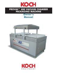
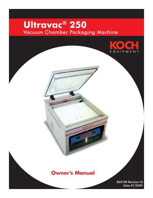
Ultravac ® <strong>250</strong><br />
Vacuum Chamber Packaging Machine<br />
860108 Revision Q<br />
Date 01/2009
TABLE OF CONTENTS<br />
General ...............................................III<br />
Specifications ....................................... IV<br />
SAFETY<br />
Personal Safety ....................................1.1<br />
Food Safety ........................................1.2<br />
General Safety Guidelines ....................1.2<br />
STARTUP<br />
Unpacking ..........................................2.1<br />
Power Requirements .............................2.1<br />
Grounding Instructions.........................2.1<br />
Vacuum Pump .................................... 2.2<br />
Gas Flush Connection ........................ 2.3<br />
Air-Assist Connection .......................... 2.3<br />
Checking Vacuum Pump Rotation ........ 2.3<br />
OPERATION<br />
Placement of Product ...........................3.1<br />
Operation with Analog Control Panel ... 3.2<br />
Operation with Digital Control Panel .... 3.3<br />
Operator Menu on Digital Panel .......... 3.4<br />
Selecting a New Program .................... 3.6<br />
Sealing with Air-Assist ......................... 3.7<br />
Gas Flush Option ............................... 3.7<br />
Double Seam Seal Option .................. 3.7<br />
MAINTENANCE<br />
Prior to Cleaning .................................4.1<br />
Cleaning Recommendations .................4.1<br />
Vacuum Pump Maintenance ................ 4.2<br />
Seal Bar Maintenance ......................... 4.2<br />
Reading the Indicators ........................ 4.3<br />
Troubleshooting ................................. 4.4<br />
Supervisor Menu on Digital Panel ........ 4.6<br />
Opening Chamber Machine ............... 4.11<br />
Changing Vacuum Pump Oil .............. 4.11<br />
Replacing Power Cord .......................4.12<br />
Replacing Potentiometer .....................4.12<br />
Maintenance Log ..............................4.13<br />
<strong>Service</strong> Log .......................................4.13<br />
860108• Q<br />
INTRODUCTION • P A G E I<br />
MAIN: 816-753-2150<br />
TOLL FREE: 800-777-5624<br />
INTERNET: kochequipment.com<br />
E-MAIL: info@kochequipment.com<br />
SCHEMATICS<br />
Designation and Function of Controls....5.1<br />
110 Volt, Single Phase ......................... 5.2<br />
220 Volt, Single Phase ........................ 5.3<br />
110 Volt, Double Seal Bar ................... 5.4<br />
220 Volt, Double Seal Bar ................... 5.5<br />
Non-Gas Flush Pneumatic Diagram ..... 5.6<br />
Gas Flush Pneumatic Diagram ............. 5.7<br />
PARTS<br />
Recommended Spare Parts ...................6.1<br />
Pump and Chassis .............................. 6.2<br />
Seal Bar ............................................ 6.4<br />
Lid and Hinge System ......................... 6.6<br />
Gas Flush Components....................... 6.8<br />
Analog Control Panel ........................6.10<br />
Digital Control Panel .........................6.12<br />
Mebner Valve ....................................6.13<br />
Miscellaneous Machine Parts ..............6.14<br />
Pump Filter Option ............................6.15<br />
REFERENCE MANUALS<br />
R5 Series Vacuum Pumps ..................... 7.1<br />
INDEX .............................................. 8.1
Specifications<br />
Figure 0.1<br />
860108• Q<br />
INTRODUCTION • P A G E IV<br />
MAIN: 816-753-2150<br />
TOLL FREE: 800-777-5624<br />
INTERNET: kochequipment.com<br />
E-MAIL: info@kochequipment.com<br />
Length (A): 483mm (19-in.)<br />
Width (B): 625mm (24.625-in.)<br />
Maximum Height (C): 826mm (32.5-in.)<br />
Working Height (D): 365mm (14.375-in.)<br />
Seal Bar Length: 406mm (16-in.)<br />
Chamber Length (E): 505mm (19.875-in.)<br />
Chamber Width (F): 422mm (16.625-in.)<br />
Chamber Height (G): 171mm (6.75-in.)<br />
Between Seal Bar and Back of Chamber (H): 451mm (17.75-in.)<br />
Between Seal Bars (double seal bar option): 416mm (16.375-in.)<br />
Vacuum Pump: 25m 3 /h (15cfm) 0.95kW (1.25-hp)<br />
Net Weight: 81-kg, 178-lbs.<br />
Electrical Connection: See Power Requirements in Section 2<br />
Capacity: 20-30 seconds per cycle
SAFETY<br />
860108• Q<br />
SAFETY • P A G E 1.1<br />
MAIN: 816-753-2150<br />
TOLL FREE: 800-777-5624<br />
INTERNET: kochequipment.com<br />
E-MAIL: info@kochequipment.com<br />
Personal Safety<br />
The procedures and guidelines herein must be followed precisely to avoid problems that can<br />
result in property damage, personal injury, or death. If you have any questions related to<br />
this information, please contact <strong>Koch</strong> Equipment <strong>Service</strong>s Inc. at (800) 777-5624.<br />
DANGER Hazardous voltage.<br />
Disconnect and lockout power before servicing machine or cleaning. Do not remove panels<br />
unless power has been disconnected, locked out, and tagged out at risk of electric shock<br />
hazard.<br />
DANGER Hazardous voltage.<br />
Improper connection of the equipment-grounding conductor can result in a risk of electric<br />
shock.<br />
WARNING<br />
Read and understand owner’s manual before using this machine. Failure to follow operating<br />
instructions could result in personal injury or damage to equipment.<br />
WARNING Explosion hazard.<br />
Do not use a gas with an oxygen content greater than 22% with gas flush option.<br />
CAUTION Tip over hazard.<br />
Only let the front foot of the chassis hang over the edge of the table.<br />
CAUTION Cleaning agents.<br />
Do not get the cleaning agents in eyes, on skin, or on clothing. Always wear rubber gloves,<br />
goggles, and protective clothing when contact is likely. Consult product manufacturer for<br />
specific details.<br />
Signal words used in classification of potential hazards are defined as follows:<br />
DANGER: Indicates an imminently hazardous situation, which, if not avoided, may result in death or<br />
serious injury.<br />
WARNING: Indicates a potentially hazardous situation, which, if not avoided, could result in death or<br />
serious injury.<br />
CAUTION: Indicates a potentially hazardous situation, which, if not avoided, may result in minor or<br />
moderate injury. Caution also indicates actions that may cause property damage.
Food Safety<br />
860108• Q<br />
SAFETY • P A G E 1.2<br />
MAIN: 816-753-2150<br />
TOLL FREE: 800-777-5624<br />
INTERNET: kochequipment.com<br />
E-MAIL: info@kochequipment.com<br />
Food Packaging<br />
While this machine is often used for food packaging and vacuum cooking, there are<br />
inherent risks associated with this packaging technique that could cause serious illness<br />
or death to the consumer of the food product. If you are using this machine for a food<br />
application, you must consult with a reputable food technologist or specialist in vacuum/<br />
modified atmosphere packaging (M.A.P.) to review the safety of your application.<br />
Gas Flush<br />
In order to ensure proper shelf life of the food product packaged in this machine, you<br />
must contact a reputable food technologist or specialist in vacuum/modified atmosphere<br />
packaging (M.A.P.) to review and develop the appropriate gas mixture for your package,<br />
and you must perform quality control and gas analysis on your finished M.A.P. packages.<br />
General Safety Guidelines<br />
Obvious safety guidelines should be observed.<br />
Be sure to turn off power to your packaging machine before any maintenance work is<br />
performed.<br />
Follow approved Lockout/Tagout procedures.<br />
Place machine on a flat, stable surface.<br />
Do not place tools, parts, or other objects on or inside machine while operating.
STARTUP<br />
Unpacking<br />
1. Carefully remove crate from the skid.<br />
2. Remove machine from skid.<br />
3. Wipe down outside of the machine.<br />
860108• Q<br />
STARTUP • P A G E 2.1<br />
MAIN: 816-753-2150<br />
TOLL FREE: 800-777-5624<br />
INTERNET: kochequipment.com<br />
E-MAIL: info@kochequipment.com<br />
Power Requirements<br />
The owner must supply the correct single phase power source in accordance with the<br />
National Electric Code. The machine is rated at 110 volt, 60 Hz, 15 amps; or 220 volt, 50<br />
Hz, 8 amp. Do not use an extension cord to connect the machine to the wall outlet.<br />
Grounding Instructions<br />
The Ultravac ® <strong>250</strong> must be grounded. In the event of malfunction or breakdown, grounding<br />
provides a path of least resistance for electric current to reduce the risk of electric shock.<br />
The unit is equipped with a equipment-grounding conductor cord and a grounding plug.<br />
The plug must be plugged into an appropriate outlet that is properly installed and grounded<br />
in accordance with all local codes and ordinances.<br />
DANGER Hazardous voltage.<br />
Improper connection of the equipment-grounding conductor can result in a risk of electric<br />
shock.<br />
The equipment-grounding conductor outer surface is green with or without yellow<br />
stripes. If repair or replacement of the cord or plug is necessary, do not connect the<br />
equipment-grounding conductor to a live terminal. Check with a qualified electrician or<br />
<strong>Koch</strong> Equipment <strong>Service</strong>s Inc. technician if the grounding instructions are not completely<br />
understood, or if there is doubt as to whether the unit is properly grounded. Do not modify<br />
the plug provided with the unit – if it will not fit the outlet; have a proper outlet installed by<br />
a qualified electrician.<br />
For 110 Volt Units<br />
This unit is for use on a nominal 110V circuit, and has a factory equipped grounding plug<br />
(see Figure 2.2A on page 2.2). A temporary adaptor (see Figure 2.2C on page 2.2), may<br />
be used to connect this plug to a two-pole receptacle (see Figure 2.2C on page 2.2) if a<br />
properly grounded outlet is not available. The temporary adaptor should be used only until<br />
a properly grounded outlet (see Figure 2.2B on page 2.2) can be installed by a qualified<br />
electrician. The green rigid ear extending from the adaptor must be held in place by the<br />
metal screw on a properly grounded outlet box cover.
Grounding Instructions<br />
860108• Q<br />
STARTUP • P A G E 2.2<br />
MAIN: 816-753-2150<br />
TOLL FREE: 800-777-5624<br />
INTERNET: kochequipment.com<br />
E-MAIL: info@kochequipment.com<br />
For 220 Volt Units<br />
This unit is for use on a nominal circuit having a rating more than 110V; or is rated more<br />
than 15 amps and used on a nominal 110V circuit, and has a factory equipped grounding<br />
plug. No adapter should be used with this unit. If the unit must be reconnected for use on<br />
a different type of electric circuit, the reconnection should be made by qualified service<br />
personnel; and after the reconnection, the appliance should comply with all local codes and<br />
ordinances.<br />
Grounding Pin<br />
A<br />
Temporary Adaptor<br />
Metal Screw<br />
Cover of Grounded<br />
Outlet Box<br />
B C<br />
Figure 2.1<br />
Vacuum Pump<br />
It is essential to check the oil level daily and to change the oil after every 500 hours of<br />
operation. Read the oil level with the machine turned off. Oil may be added until the level<br />
reaches the MAX level shown in the sight glass on the pump. Refer to the pump manual<br />
supplied with the machine for details on changing the oil.<br />
OIL SIGHT HOLE<br />
MAX<br />
MIN<br />
Figure 2.2
860108• Q<br />
STARTUP • P A G E 2.3<br />
MAIN: 816-753-2150<br />
TOLL FREE: 800-777-5624<br />
INTERNET: kochequipment.com<br />
E-MAIL: info@kochequipment.com<br />
Gas Flush Connection<br />
The owner must supply a suitable regulator with a range of 0 to 60 p.s.i. We recommend<br />
using food-grade flexible hose with a 1/4-in. I.D. and a maximum length of 15-ft. Maximum<br />
regulator pressure is 15 p.s.i.<br />
Air-Assist Connection<br />
The machine is equipped with a regulator for air-assisted sealing. The hose barb will<br />
accept 1/4-in. I.D. hose. The recommended air supply is 75 p.s.i. at 6 c.f.m. The maximum<br />
regulator setting is 40 p.s.i.<br />
Checking Vacuum Pump Rotation<br />
Caution: Check oil level of pump before starting pump (please refer to pump manual).<br />
To check the direction of the pump rotation, briefly engage the “POWER ON” switch and<br />
observe the motor fan at the end of the pump. The fan should rotate as indicated by the<br />
arrow on the fan cover. To correct the rotation, switch any two phases in the plug.
OPERATION<br />
Placement of Product<br />
For best sealing results, it is important to:<br />
•<br />
Check the pump oil level daily.<br />
• Select a pouch that fits the product.<br />
• Carefully load the product into the pouch.<br />
860108• Q<br />
OPERATION • P A G E 3.1<br />
MAIN: 816-753-2150<br />
TOLL FREE: 800-777-5624<br />
INTERNET: kochequipment.com<br />
E-MAIL: info@kochequipment.com<br />
• Keep the product and the product residue away from the seal area of the pouch.<br />
• Place the product as far into the pouch as possible.<br />
• Maintain an equal amount of the product above and below the seal bar (see figure 3.1,<br />
below on use of filler plates).<br />
•<br />
Use Filler Plates for raising the height of the product.<br />
• Lay the pouch flat on the seal area, keeping the pouch free of wrinkles.<br />
• Place the pouch so that the open end is inside the chamber when the lid is closed.<br />
Figure 3.1<br />
PRODUCT HALF HEIGHT<br />
EVEN WITH TOP OF<br />
SEAL BAR
Operation with Analog Control Panel<br />
The analog control panel is shown below, figure 3.2.<br />
860108• Q<br />
OPERATION • P A G E 3.2<br />
MAIN: 816-753-2150<br />
TOLL FREE: 800-777-5624<br />
INTERNET: kochequipment.com<br />
E-MAIL: info@kochequipment.com<br />
The range for timed vacuum is 0 to 55 seconds and is controlled by the Vacuum<br />
Potentiometer. We suggest an initial setting of “3” on the dial.<br />
Seal impulse is the length of time the seal bar is turned on and can range from 0 to<br />
2 seconds. The impulse time is controlled by the Seal Potentiometer. <strong>Koch</strong> Equipment<br />
recommends an initial setting of “6” on the potentiometer. This setting will vary according<br />
to the thickness of the pouch. Thinner pouches will require a lower setting while thicker<br />
pouches will require a higher setting.<br />
Experiment with both settings to achieve the best results.<br />
Figure 3.2<br />
POWER SWITCH<br />
VACUUM<br />
POTENTIOMETER<br />
VACUUM LIGHT<br />
(GREEN)<br />
SEAL<br />
POTENTIOMETER<br />
VACUUM<br />
INDICATOR<br />
SEAL LIGHT<br />
(RED)
860108• Q<br />
OPERATION • P A G E 3.3<br />
MAIN: 816-753-2150<br />
TOLL FREE: 800-777-5624<br />
INTERNET: kochequipment.com<br />
E-MAIL: info@kochequipment.com<br />
Operation with Digital Control Panel<br />
The digital control panel allows the user more options than the standard control panel. The<br />
embedded microprocessor controls each sequence of the packaging operation. Settings for<br />
the vacuum, gas, and sealing are entered as parameters through the keypad. This allows<br />
the user to custom program every step of the packaging process. The precise vacuum<br />
and gas pressures are controlled by a pressure based sensor. The vacuum pressure, gas<br />
pressure, and seal time are displayed on a large 16-character LCD backlit readout, which<br />
is easily readable in all lighting conditions. As each sequence is performed, the real-time<br />
pressure level or cycle time is displayed.<br />
The digital front panel can save up to 100 pre-programmed routines, which can be<br />
retrieved at any time for specific packaging applications. With the supervisor security feature<br />
turned on, these programs cannot be inadvertently changed.<br />
The VACPLUS option allows the operator to run the pump from 0 to 20 seconds after the set<br />
vacuum level is achieved.<br />
The Gas Flush option allows the operator to introduce an inert gas into the chamber after<br />
the vacuum stage. This option can be used as a filler to prevent crushing of the product<br />
after sealing, as a means to prolong shelf life or as a means to maintain desirable product<br />
appearance.<br />
The digital front panel has an auto stop, which will automatically seal if the preset vacuum is<br />
not reached. This feature decreases the cycle time and optimizes the vacuum level of each<br />
product.<br />
The digital front panel, which includes the keypad, illuminated display, and microprocessor,<br />
uses sealed components and is conformal coated in a moisture-proof coating. The digital<br />
front panel meets or exceeds the requirements of NEMA 4. The front of the digital display is<br />
sealed and flush for easy cleaning.<br />
The digital control has both pulsed vacuum and pulsed venting options for fragile product.<br />
The digital control has a maintenance screen for testing valves and a special loop option for<br />
multiple vacuum/gas cycles before sealing.<br />
Figure 3.3
Operator Menu on Digital Panel<br />
RUNNING PROG: 1<br />
VACUUM: 98<br />
VACPLUS: 4.0<br />
SEAL: 1.2<br />
860108• Q<br />
+<br />
-<br />
+<br />
PROGRAM<br />
PROGRAM<br />
YES<br />
NO<br />
YES<br />
- NO<br />
+<br />
-<br />
+<br />
PROGRAM<br />
PROGRAM<br />
YES<br />
NO<br />
YES<br />
- NO<br />
OPERATION • P A G E 3.4<br />
MAIN: 816-753-2150<br />
TOLL FREE: 800-777-5624<br />
INTERNET: kochequipment.com<br />
E-MAIL: info@kochequipment.com<br />
NOTE: if the supervisor has set security on, these settings cannot be changed.<br />
Figure 3.4<br />
This is the Main Menu screen. When the<br />
machine starts up, the last program that was<br />
run will be the current program shown in<br />
the window. To set the operating parameters<br />
for the program shown press the MENU key.<br />
VACUUM is set to % vacuum using the UP<br />
and DOWN Arrow Keys.<br />
The range is 30% to 99%.<br />
Press the MENU key.<br />
VACPLUS may be set from 0 to 20 seconds.<br />
A setting greater than 0 allows the pump<br />
to continue evacuating the chamber (for<br />
the specified number of seconds) after the<br />
pressure in the chamber has reached the %<br />
vacuum set in the vacuum menu.<br />
Press the MENU key.<br />
The SEAL setting is in seconds. Use the UP<br />
and DOWN arrow keys to change the seal<br />
time. The range is 0 to 2 seconds.<br />
Press the MENU key.
Operator Menu on Digital Panel (continued)<br />
GAS: YES<br />
GAS: 75<br />
Figure 3.5<br />
860108• Q<br />
+<br />
-<br />
+<br />
-<br />
PROGRAM<br />
PROGRAM<br />
YES<br />
NO<br />
YES<br />
NO<br />
OPERATION • P A G E 3.5<br />
MAIN: 816-753-2150<br />
TOLL FREE: 800-777-5624<br />
INTERNET: kochequipment.com<br />
E-MAIL: info@kochequipment.com<br />
If the machine is equipped with the gas<br />
option, it can be turned on or off by pressing<br />
the UP or DOWN arrow keys.<br />
Press the MENU key.<br />
Gas is set to % gas using the UP and DOWN<br />
Arrow Keys. This value also corresponds to<br />
the vacuum reading inside the chamber. It<br />
is recommended to use pulse vent when gas<br />
flushing to a low % vacuum. The range is<br />
98% to 30%.<br />
Press the MENU key.<br />
WARNING Explosion hazard.<br />
Do not use a gas with an oxygen content greater than 22% with gas flush option.
Selecting a New Program<br />
RUNNING PROG: 1<br />
ENTER PROGAM: 2<br />
Figure 3.6<br />
860108• Q<br />
+<br />
-<br />
+<br />
-<br />
PROGRAM<br />
PROGRAM<br />
YES<br />
NO<br />
YES<br />
NO<br />
OPERATION • P A G E 3.6<br />
MAIN: 816-753-2150<br />
TOLL FREE: 800-777-5624<br />
INTERNET: kochequipment.com<br />
E-MAIL: info@kochequipment.com<br />
From the Main Menu, use the UP and<br />
DOWN Arrow Keys to select a new program.<br />
Press the UP Arrow to switch to program 2<br />
(or any of the ten programs.)<br />
New parameters may be set for vacuum,<br />
seal time and gas for program 2 (following<br />
the procedure described in the previous<br />
example) or simply close the lid on the<br />
machine and run program 2.
860108• Q<br />
OPERATION • P A G E 3.7<br />
MAIN: 816-753-2150<br />
TOLL FREE: 800-777-5624<br />
INTERNET: kochequipment.com<br />
E-MAIL: info@kochequipment.com<br />
Sealing with Air-Assist<br />
All machines are equipped with regulators for air-assisted sealing. Set the air pressure<br />
regulator to 20 p.s.i. increasing to a maximum of 40 p.s.i. While a good seal can be<br />
obtained without air-assist, use air-assist when:<br />
• Gas back-flushing above average pressure.<br />
• Using shrink pouches.<br />
• Packaging a product that easily contaminates the seal area of the pouch.<br />
• Trying to overlap pouches.<br />
• Wrinkles cannot be avoided in the seal area.<br />
•<br />
Using the Double Seam Seal Option.<br />
Gas Flush Option<br />
Gas flushing is the introduction of an inert gas into the chamber after the vacuum stage<br />
is finished. Gas can be used as a filler to prevent crushing of the product after sealing, as<br />
a means to prolong shelf life or as a means to maintain desirable product appearance.<br />
Commonly used gasses include nitrogen, carbon dioxide, or a mixture of both. Consult your<br />
local gas supplier to select the proper gas for your product.<br />
WARNING Explosion hazard.<br />
Do not use a gas with an oxygen content greater than 22% with gas flush option.<br />
Double Seam Seal Option<br />
All machines are equipped with standard seal bars having a single seal element per seal<br />
bar. The double seam seal bars have two seal elements per seal bar. We recommend using<br />
air-assisted sealing with this option to achieve best results.
860108• Q<br />
THIS PAGE LEFT BLANK INTENTIONALLY.<br />
OPERATION • P A G E 3.8<br />
MAIN: 816-753-2150<br />
TOLL FREE: 800-777-5624<br />
INTERNET: kochequipment.com<br />
E-MAIL: info@kochequipment.com
MAINTENANCE<br />
860108• Q<br />
MAINTENANCE • P A G E 4.1<br />
MAIN: 816-753-2150<br />
TOLL FREE: 800-777-5624<br />
INTERNET: kochequipment.com<br />
E-MAIL: info@kochequipment.com<br />
Prior to Cleaning<br />
Every environment and application is different; therefore, <strong>Koch</strong> Equipment LLC cannot<br />
provide cleaning instructions to guarantee microbiological sanitation. <strong>Koch</strong> Equipment<br />
requests that the owner of this machine consult with sanitation experts to review the<br />
unit working in their particular environment to develop a robust cleaning schedule and<br />
methodology, followed by bacterial testing to ensure satisfactory cleaning procedures are<br />
followed.<br />
Cleaning Recommendations<br />
Before cleaning the machine, turn power off; disconnect the main power, and lockout the<br />
connection.<br />
DANGER Hazardous voltage.<br />
Disconnect and lockout power before servicing machine or cleaning. Do not remove panels<br />
unless power has been disconnected and locked out at risk of electric shock hazard.<br />
Check with the detergent and sanitizer manufacturers that their products are compatible<br />
with the listed materials.<br />
CAUTION Cleaning agents.<br />
Do not get the cleaning agents in eyes, on skin, or on clothing. Always wear rubber gloves,<br />
goggles, and protective clothing when contact is likely. Consult product manufacturer for<br />
specific details.<br />
Never hose down the machine. Damage caused by hosing or high pressure washing is not<br />
covered under warranty.<br />
1. Filler Plates: Remove filler plates. The filler plates are made from polyethylene. Clean,<br />
sanitize, and dry. High pressure water spray can be used on the filler plates.<br />
2. Lid and Backup Strip: The lid is constructed of acrylic. Use only nonabrasive soap and<br />
water. Do not use window sprays or kitchen scouring compounds. The backup strip is<br />
made of silicone. Clean, sanitize, and dry.<br />
3. Seal Bars: Remove the seal bars by first lifting them up off of the guide rods. Remove<br />
the wire connectors from the adapter clips on the seal bar and remove the seal bar from<br />
the machine. The seal bars are made of aluminum and phenolic. Clean, sanitize, and<br />
dry.<br />
4. Chamber and Base: The chamber is made of 304 stainless steel and the base is made<br />
from polyurethane. Clean, sanitize, and dry, including under the seal bar bladder (not<br />
removable).<br />
5. Clean under the machine.<br />
6. Reinstall the seal bar.<br />
7. Use bacteriological testing to insure cleaning process.
Step 1.<br />
Remove the seal bars from the machine. Pull<br />
off the Teflon ® tape strip and discard. Clean<br />
off any remaining Teflon ® tape adhesive<br />
using acetone or an equivalent solvent.<br />
860108• Q<br />
Teflon TEFLON TAPE<br />
SEAL ELEMENT<br />
® tape Seal element<br />
MAINTENANCE • P A G E 4.2<br />
MAIN: 816-753-2150<br />
TOLL FREE: 800-777-5624<br />
INTERNET: kochequipment.com<br />
E-MAIL: info@kochequipment.com<br />
Vacuum Pump Maintenance<br />
Consult the pump manufacturer’s manual provided with the machine for detailed<br />
information.<br />
Seal Bar Maintenance<br />
The following illustrations show replacement of the seal elements for the seal bars.<br />
Step 2.<br />
Using a 2mm Allen wrench, loosen the set<br />
screws for the cut-off wire and the seal<br />
element on both ends of the seal bar and<br />
discard.<br />
SET Set SCREW screw<br />
2mm ALLEN Allen<br />
Figure 4.1 Figure 4.2<br />
wrench<br />
WRENCH<br />
Step 3.<br />
If you are replacing the L-shaped spring retainer and the spring at this time, loosen the set<br />
screw and remove the old spring retainer and spring and install the new ones. Adjust the<br />
spring retainer to allow a 1/8-in. gap between the spring retainer and the seal bar. This will<br />
allow the seal element to remain under tension after tightening the seal element.<br />
TIGHTENING TOOL<br />
Figure 4.3<br />
BRASS CONTACT<br />
SLOTTED TIP<br />
SCREWDRIVER
860108• Q<br />
MAINTENANCE • P A G E 4.3<br />
MAIN: 816-753-2150<br />
TOLL FREE: 800-777-5624<br />
INTERNET: kochequipment.com<br />
E-MAIL: info@kochequipment.com<br />
Reading the Indicators<br />
If your machine is controlled by a digital control module (with touch pad), this design to aids<br />
in troubleshooting. The digital panel has indicator lights mounted on the front below the<br />
ON/OFF switch. The indicator lights correspond to the operating devices and should turn on<br />
and off in the following sequence when the machine lid is closed:<br />
1. Vacuum Pump [C-1]<br />
2. Gas Flush Valve [SOL-3] (optional)<br />
3. Seal Bladder Valve [SOL-2]<br />
(stays on until completion of cycle)<br />
4. Seal Impulse Contactor [C-2]<br />
5. Ventilation Valve [SOL-1]<br />
The device should be operating when the light is illuminated. If the lights illuminate in the<br />
proper sequence, but there is still a problem, look for the problem in the operating device<br />
itself. If the lights do not sequence properly, look for a problem in the control module.
Troubleshooting<br />
Problem Indications Remedy<br />
Machine will not start Green power “ON” light not<br />
lit when switch is turned on<br />
860108• Q<br />
MAINTENANCE • P A G E 4.4<br />
MAIN: 816-753-2150<br />
TOLL FREE: 800-777-5624<br />
INTERNET: kochequipment.com<br />
E-MAIL: info@kochequipment.com<br />
Make sure that the power<br />
requirements match those given<br />
on the nameplate. Also, check<br />
fuse F-2; replace if blown.<br />
Vacuum pump does not run Make sure that the power<br />
requirements match those given<br />
on the nameplate<br />
No vacuum When lid is closed, indicator<br />
light (VAC) is “OFF” on the<br />
control module<br />
Check lid switches LS-1 for proper<br />
adjustment<br />
Vacuum not pulling lid down Check intake screen in vacuum<br />
pump hose barb for blockage,<br />
pieces of bags, labels, bone, etc.<br />
Longer vacuum cycle times Check intake screen in vacuum<br />
pump hose barb for blockage<br />
No gas flush (optional) If indicator light (GAS) is lit Check for proper gas pressure<br />
going into gas inlet<br />
Check for proper operation of gas<br />
flush valve (SOL-3)<br />
Chamber not venting<br />
(lid will not open)<br />
If indicator light (GAS) is not<br />
lit<br />
Lid will not open and red<br />
indicator light “VENT” on<br />
control module is lit<br />
“VENT” indicator light is not<br />
lit<br />
NOTE: Lid can be released by pulling the hose off of<br />
the vacuum gauge to remove product.<br />
Check gas flush potentiometer on<br />
analog control module or possible<br />
defective digital control panel<br />
Check ventilation valve SOL-1 for<br />
proper operation<br />
Check cool down potentiometer<br />
on analog control module or<br />
possible defective digital control<br />
panel
Troubleshooting<br />
Problem Indications Remedy<br />
Improper or no<br />
sealing<br />
860108• Q<br />
Seal bladder light on control<br />
module is lit, but the seal bar<br />
does not go up<br />
The seal bar is not heating<br />
up even though the red<br />
seal light on the front panel<br />
comes on<br />
The red seal light on the<br />
front panel either does not<br />
light for the proper length of<br />
time (½ to 1 second) or does<br />
not light at all<br />
MAINTENANCE • P A G E 4.5<br />
MAIN: 816-753-2150<br />
TOLL FREE: 800-777-5624<br />
INTERNET: kochequipment.com<br />
E-MAIL: info@kochequipment.com<br />
Check to make sure that the<br />
regulator knob is turned fully<br />
clockwise or, if air-assist is used,<br />
set to the recommended pressure<br />
Check seal bladder valve SOL-2<br />
for proper operation<br />
Check seal bar connection points<br />
and clips for corrosion and proper<br />
tension<br />
Check for broken seal element<br />
Check seal bar fuse F-1 located on<br />
the analog or digital panel. If the<br />
machine is 110VAC with two seal<br />
bars, F-1 is located on the chassis.<br />
Make sure the seal impulse<br />
potentiometer is set high enough<br />
or check for possible defective<br />
digital control panel<br />
NOTE: For proper sealing, three things must occur:<br />
1. The seal bar must come down and place adequate pressure between the seal bar and<br />
the backup strip.<br />
2. The seal element must heat up sufficiently to fuse the pouch.<br />
3. The pouch must be allowed to cool for a time to ensure a good “set.”
860108• Q<br />
MAINTENANCE • P A G E 4.6<br />
MAIN: 816-753-2150<br />
TOLL FREE: 800-777-5624<br />
INTERNET: kochequipment.com<br />
E-MAIL: info@kochequipment.com<br />
Supervisor Menu on Digital Panel<br />
Untrained personnel should not alter any setting in the supervisor menu.<br />
RUNNING PROG: 1<br />
COOLDOWN: 4.0<br />
SECURITY: NO<br />
# PROGRAMS: 10<br />
PROGRAM<br />
The following are parameters that<br />
can only be set in the supervisor<br />
menu.<br />
TEST: YES<br />
Figure 4.4<br />
+<br />
-<br />
+<br />
-<br />
+<br />
-<br />
+<br />
-<br />
+<br />
-<br />
PROGRAM<br />
PROGRAM<br />
PROGRAM<br />
PROGRAM<br />
NO<br />
YES<br />
NO<br />
YES<br />
NO<br />
YES<br />
NO<br />
YES<br />
NO<br />
YES<br />
This is the Main Menu screen. When the machine<br />
starts up, the last program that was run will be the<br />
current program shown in the window.<br />
Press and hold down both arrow keys for at least<br />
three seconds to enter the supervisor menu.<br />
COOLDOWN is the time that the machine waits<br />
after sealing the bag/pouch before the seal bars retract.<br />
This allows time for the actual seal to cool down and<br />
take set. The range is 1 to 8 seconds.<br />
Press the MENU key.<br />
SECURITY can be turned on by selecting “YES.” If<br />
security is on, the operator menu will be read only and<br />
the operator will not be able to change any settings.<br />
Press the MENU key.<br />
This specifies the maximum number of programs that<br />
may be saved in memory. Each program may have its<br />
own set of unique parameters. The range is 1 to 10.<br />
Press the MENU key.<br />
If TEST is set to “YES” (using the UP arrow key), the<br />
vacuum and vent valve may be operated manually. The<br />
UP arrow key activates the vacuum valve, the DOWN<br />
arrow key activates the vent valve, and pressing both<br />
at the same time turns them both off. As you activate<br />
either valve the vacuum pressure is displayed.<br />
Press the MENU key.
Supervisor Menu on Digital Panel<br />
PULSE VAC: YES<br />
PULSE TO: 95<br />
PULSE ON: 1.2<br />
PULSE OFF: 1.0<br />
Figure 4.5<br />
860108• Q<br />
+<br />
-<br />
+<br />
-<br />
+<br />
-<br />
+<br />
-<br />
PROGRAM<br />
PROGRAM<br />
PROGRAM<br />
PROGRAM<br />
YES<br />
NO<br />
YES<br />
NO<br />
YES<br />
NO<br />
YES<br />
NO<br />
MAINTENANCE • P A G E 4.7<br />
MAIN: 816-753-2150<br />
TOLL FREE: 800-777-5624<br />
INTERNET: kochequipment.com<br />
E-MAIL: info@kochequipment.com<br />
PULSE VAC allows for a more controlled<br />
vacuuming process. Rather than simply<br />
opening the vacuum valve for a continuous<br />
vacuum, the valve is opened and closed<br />
repeatedly until the chamber reaches the set<br />
vacuum level.<br />
Press the MENU key.<br />
The % vacuum reached by pulsing the<br />
vacuum valve before the vacuum valve<br />
opens completely to full evacuate the<br />
chamber. The range is 99% to 20%.<br />
Press the MENU key.<br />
The vacuum valve is turned on during the<br />
vacuum cycle in seconds. The range is 0 to 3<br />
seconds.<br />
Press the MENU key.<br />
The vacuum valve is turned off during the<br />
vacuum cycle in seconds. The range is 0 to 3<br />
seconds.<br />
Press the MENU key.
Supervisor Menu on Digital Panel<br />
PULSE VENT: YES<br />
PULSE TO: 50<br />
PULSE ON: 1.2<br />
PULSE OFF: 1.0<br />
Figure 4.6<br />
860108• Q<br />
+<br />
-<br />
+<br />
-<br />
+<br />
-<br />
+<br />
-<br />
PROGRAM<br />
PROGRAM<br />
PROGRAM<br />
PROGRAM<br />
YES<br />
NO<br />
YES<br />
NO<br />
YES<br />
NO<br />
YES<br />
NO<br />
MAINTENANCE • P A G E 4.8<br />
MAIN: 816-753-2150<br />
TOLL FREE: 800-777-5624<br />
INTERNET: kochequipment.com<br />
E-MAIL: info@kochequipment.com<br />
PULSE VENT allows for a more controlled<br />
venting process. Rather than simply opening<br />
up the valve for a continuous vent the valve<br />
is opened and closed repeatedly until the<br />
chamber vents back to atmosphere pressure.<br />
Press the MENU key.<br />
The % vacuum reached by pulsing the vent<br />
valve before the vent valve opens completely<br />
to fully vent the chamber. The range is 90%<br />
to 30%.<br />
Press the MENU key.<br />
The vent valve is turned on during the<br />
vent cycle in seconds. The range is 0 to 3<br />
seconds.<br />
Press the MENU key.<br />
The vent valve is turned off during the<br />
vent cycle in seconds. The range is 0 to 3<br />
seconds.<br />
Press the MENU key.
Supervisor Menu on Digital Panel<br />
PULSE VENT: YES<br />
PULSE TO: 50<br />
PULSE ON: 1.2<br />
PULSE OFF: 1.0<br />
Figure 4.7<br />
860108• Q<br />
+<br />
-<br />
+<br />
-<br />
+<br />
-<br />
+<br />
-<br />
PROGRAM<br />
PROGRAM<br />
PROGRAM<br />
PROGRAM<br />
YES<br />
NO<br />
YES<br />
NO<br />
YES<br />
NO<br />
YES<br />
NO<br />
MAINTENANCE • P A G E 4.9<br />
MAIN: 816-753-2150<br />
TOLL FREE: 800-777-5624<br />
INTERNET: kochequipment.com<br />
E-MAIL: info@kochequipment.com<br />
PULSE VENT allows for a more controlled<br />
venting process. Rather than simply opening<br />
up the valve for a continuous vent, the valve<br />
is opened and closed repeatedly until the<br />
chamber vents back to atmosphere pressure.<br />
Press the MENU key.<br />
The % vacuum reached by pulsing the vent<br />
valve before the vent valve opens completely<br />
to fully vent the chamber. The range is 90%<br />
to 30%.<br />
Press the MENU key.<br />
The vent valve is turned on during the<br />
vent cycle in seconds. The range is 0 to 3<br />
seconds.<br />
Press the MENU key.<br />
The vent valve is turned off during the<br />
vent cycle in seconds. The range is 0 to 3<br />
seconds.<br />
Press the MENU key.
Supervisor Menu on Digital Panel<br />
LOOP #: 1<br />
EXIT GAS: YES<br />
VAC ERROR: ON<br />
Figure 4.8<br />
860108• Q<br />
+<br />
-<br />
+<br />
-<br />
+<br />
-<br />
PROGRAM<br />
PROGRAM<br />
PROGRAM<br />
YES<br />
NO<br />
YES<br />
NO<br />
YES<br />
NO<br />
MAINTENANCE • P A G E 4.10<br />
MAIN: 816-753-2150<br />
TOLL FREE: 800-777-5624<br />
INTERNET: kochequipment.com<br />
E-MAIL: info@kochequipment.com<br />
If the machine is equipped with the loop<br />
option, this is the number of vacuum/gas<br />
cycles the control will perform prior to the<br />
seal and vent. The range is 1 to 5 cycles. The<br />
default is 1.<br />
Press the MENU key.<br />
If the loop # is set greater than 1, the control<br />
can be set to exit the loop on either the last<br />
gas cycle or the last vacuum cycle prior to<br />
sealing. The DOWN arrow key indicates<br />
“NO” and the UP arrow key indicates “YES.”<br />
Press the MENU key.<br />
VAC ERROR is an option that is turned ON<br />
or OFF. If set OFF, default, the machine<br />
will time out if the preset vacuum is not<br />
reached in 30 seconds, and the machine<br />
with complete the cycle. If set ON and the<br />
machine does not reach the preset vacuum<br />
in thirty seconds, then the panels will display<br />
VAC ERROR and vent the chamber without<br />
sealing.
Opening Chamber Machine<br />
860108• Q<br />
MAINTENANCE • P A G E 4.11<br />
MAIN: 816-753-2150<br />
TOLL FREE: 800-777-5624<br />
INTERNET: kochequipment.com<br />
E-MAIL: info@kochequipment.com<br />
1. Turn the power switch to the “OFF” position and disconnect the power cord from the wall<br />
receptacle.<br />
DANGER Hazardous voltage.<br />
Disconnect and lockout power before servicing machine or cleaning. Do not remove panels<br />
unless power has been disconnected and locked out at risk of electric shock hazard.<br />
2. Remove the filler plates and seal bar from inside the machine.<br />
3. Remove the lower right- and lower left-hand screws located on the outside rear of the<br />
machine’s stainless steel cabinet. Lifting on the back edge of the basin, tilt the top of the<br />
machine forward onto the table.<br />
Changing Vacuum Pump Oil<br />
1. Open the machine (see above).<br />
2. A trough and hole is located toward the front of the machine, between the pump and<br />
front edge of the chassis. Slide the machine over to the edge of the table with the hole<br />
over the edge of the table. Position an oil collection pan underneath this hole.<br />
CAUTION Tip Over Hazard.<br />
Only let the front foot of the chassis hang over the edge of the table.<br />
3. Loosen and remove the Oil Filler Cap with a 1¼-in. open end wrench.<br />
4. Loosen the Oil Drain Plug located to the front and lower middle on the pump with a<br />
1¼-in. open end wrench. Remove the plug slowly to control the flow of oil.<br />
5. With the oil drained, replace the Oil Drain Plug and wipe any excess oil out of the trough<br />
in the chassis.<br />
6. Fill the pump with oil until the level is between the minimum and maximum lines on the<br />
Oil Sight Glass. Replace the Oil Filler Cap.<br />
7. Tilt the machine back down onto the chassis. Plug the power cord back into the wall<br />
receptacle.<br />
8. Cycle the machine a couple of times, unplug, and tilt the machine up to check the Oil<br />
Level. Add oil if necessary. Tilt the machine back down and replace the two screws in the<br />
rear of the machine.
Replacing Power Cord<br />
860108• Q<br />
MAINTENANCE • P A G E 4.12<br />
MAIN: 816-753-2150<br />
TOLL FREE: 800-777-5624<br />
INTERNET: kochequipment.com<br />
E-MAIL: info@kochequipment.com<br />
1. Turn the power switch to the “OFF” position and disconnect the power cord from the wall<br />
receptacle.<br />
DANGER Hazardous voltage.<br />
Disconnect and lockout power before servicing machine or cleaning. Do not remove panels<br />
unless power has been disconnected and locked out at risk of electric shock hazard.<br />
2. Open the machine as described in “ Opening Chamber Machine” on page 4.11.<br />
3. Loosen the cord grip nut on the rear of the machine. Remove the cord from the cable<br />
clamps on the bottom of the chamber. Disconnect the cord from the control panel.<br />
4. Route the new power cord through the cord grip on the rear and through the cable<br />
clamps on the bottom of the chamber.<br />
5. Connect the new power cord to the control panel as shown in the table below.<br />
Connect to Terminal 110 Volt Wire Color 220 Volt Wire Color<br />
Terminal 8 Green (Ground) Green/Yellow<br />
Terminal 7 White Brown<br />
Terminal 6 Black Blue<br />
Replacing Potentiometer<br />
Refer to Parts, “ Analog Control Panel,” for the disassembly of the panel. Remove the<br />
potentiometer by unbending the mounting tabs holding the potentiometer to the circuit<br />
board. Pull the potentiometer out of the circuit board.<br />
Figure 4.9<br />
MOUNTING TABS
860108• Q<br />
MAINTENANCE • P A G E 4.13<br />
MAIN: 816-753-2150<br />
TOLL FREE: 800-777-5624<br />
INTERNET: kochequipment.com<br />
E-MAIL: info@kochequipment.com<br />
Maintenance Log<br />
A maintenance log is a journal of all maintenance performed. Each entry includes a<br />
date, maintenance performed (details about the type of work done), and technician (who<br />
performed the maintenance). The maintenance log is also a place where a schedule is kept<br />
for further maintenance.<br />
A maintenance log will clearly show oil changes, daily inspections, Teflon ® tape<br />
replacement, and so on. A master copy has been provided on page 4.14, please create a<br />
copy and store in the back of this owner’s manual.<br />
<strong>Service</strong> Log<br />
A service log is a journal of all service work performed. Each entry includes a date, service<br />
provided (details about the type of service), and technician (who performed the service).<br />
A service log will clearly show training provided, frequent wear items, and so on. A master<br />
copy has been provided on page 4.15, please create a copy and store in the back of this<br />
owner’s manual.
SCHEMATICS<br />
Designation and Function of Controls<br />
The following designations are found on the Electrical Diagrams:<br />
Limit Switches:<br />
LS-1 Chamber Cycle Start Switch<br />
Contactors and Relays:<br />
C-1 Vacuum Pump Contactor (for 220 VAC)<br />
C-2 Seal Impulse Contactor (for double seal bar)<br />
Overloads and Fusing:<br />
OL-1 Vacuum Pump Motor Overload<br />
F-1 Seal Bar Fuse<br />
F-3 Control Power Fuse<br />
Control Modules:<br />
MCC Master Control Circuit Board<br />
Transformers:<br />
T-1 Seal Impulse Transformer<br />
Motors:<br />
M-1 Vacuum Pump<br />
Potentiometers:<br />
POT-1 Vacuum Time Potentiometer<br />
POT-2 Sealing Impulse Potentiometer<br />
Solenoid Valves:<br />
SOL-1 Ventilation Solenoid Valve<br />
SOL-2 Seal Bladder Solenoid Valve<br />
SOL-3 Gas Flush Solenoid Valve<br />
Miscellaneous Valves:<br />
V1 Quick Exhaust Valve (gas flush option)<br />
860108• Q<br />
SCHEMATICS • P A G E 5.1<br />
MAIN: 816-753-2150<br />
TOLL FREE: 800-777-5624<br />
INTERNET: kochequipment.com<br />
E-MAIL: info@kochequipment.com
110 Volt, Single Phase<br />
Analog/Digital Control Panel<br />
18<br />
LS-1<br />
17<br />
LID<br />
SWITCH<br />
860108• Q<br />
16<br />
SOL-1<br />
VENT<br />
VALVE<br />
SOLENOID<br />
MASTER CONTROL CIRCUITBOARD<br />
15<br />
14<br />
SOL-2<br />
13<br />
SEAL<br />
VALVE<br />
SOLENOID<br />
T1<br />
SEAL<br />
TRANSFORMER<br />
12<br />
SOL-3<br />
H4<br />
11<br />
GAS<br />
VALVE<br />
SOLENOID<br />
110V<br />
H3<br />
X3<br />
48V<br />
10<br />
H2<br />
X2<br />
SEAL<br />
ELEMENT<br />
110V<br />
9<br />
H1<br />
8<br />
110 V<br />
SINGLE PHASE<br />
SCHEMATICS • P A G E 5.2<br />
7<br />
GND NEU<br />
6<br />
LINE<br />
5<br />
MAIN: 816-753-2150<br />
TOLL FREE: 800-777-5624<br />
INTERNET: kochequipment.com<br />
E-MAIL: info@kochequipment.com<br />
4<br />
2<br />
1<br />
3<br />
GRD<br />
2<br />
1<br />
THERMAL<br />
OL-1<br />
M1<br />
VACUUM PUMP<br />
19<br />
CHASSIS GROUND
220 Volt, Single Phase<br />
Analog/Digital Control Panel<br />
18<br />
LS-1<br />
17<br />
LID<br />
SWITCH<br />
860108• Q<br />
16<br />
MASTER CONTROL CIRCUITBOARD<br />
SOL-1<br />
15<br />
VENT<br />
VALVE<br />
SOLENOID<br />
14<br />
SOL-2<br />
13<br />
SEAL<br />
VALVE<br />
SOLENOID<br />
T-1<br />
SEAL<br />
TRANSFORMER<br />
12<br />
SOL-3<br />
H4<br />
11<br />
GAS<br />
VALVE<br />
SOLENOID<br />
220V<br />
H3<br />
X3<br />
48V<br />
10<br />
H2<br />
X2<br />
SEAL<br />
ELEMENT<br />
220V<br />
9<br />
H1<br />
L1<br />
T1<br />
8<br />
C-1<br />
GND NEU<br />
220 V<br />
SINGLE PHASE<br />
LINE<br />
SCHEMATICS • P A G E 5.3<br />
7<br />
L2<br />
T2<br />
6<br />
5<br />
MAIN: 816-753-2150<br />
TOLL FREE: 800-777-5624<br />
INTERNET: kochequipment.com<br />
E-MAIL: info@kochequipment.com<br />
4<br />
A1 A2 95<br />
CHASSIS GROUND<br />
96<br />
2<br />
1<br />
3<br />
GRD<br />
2<br />
C-1 OL-1<br />
1<br />
M-1<br />
VACUUM PUMP<br />
19
110 Volt, Double Seal Bar<br />
Analog/Digital Control Panel<br />
18<br />
LS-1<br />
17<br />
LID<br />
SWITCH<br />
860108• Q<br />
16<br />
SOL-1<br />
VENT<br />
VALVE<br />
SOLENOID<br />
MASTER CONTROL CIRCUITBOARD<br />
15<br />
14<br />
SOL-2<br />
13<br />
SEAL<br />
VALVE<br />
SOLENOID<br />
T-1<br />
SEAL<br />
TRANSFORMER<br />
12<br />
SOL-3<br />
11<br />
GAS<br />
VALVE<br />
SOLENOID<br />
T1<br />
F-1<br />
H1<br />
X4<br />
6<br />
5<br />
110V<br />
H2<br />
X2<br />
10<br />
9<br />
SEAL<br />
IMPULSE<br />
CONTACTOR<br />
C-2<br />
48V<br />
H3<br />
X3<br />
C-2<br />
FRONT SEAL<br />
ELEMENT<br />
CUT WIRE<br />
14<br />
13<br />
T2<br />
H4<br />
110V<br />
X1<br />
8<br />
GND NEU<br />
110 V<br />
SINGLE PHASE<br />
LINE<br />
SCHEMATICS • P A G E 5.4<br />
7<br />
6<br />
REAR SEAL<br />
ELEMENT<br />
CUT WIRE<br />
5<br />
MAIN: 816-753-2150<br />
TOLL FREE: 800-777-5624<br />
INTERNET: kochequipment.com<br />
E-MAIL: info@kochequipment.com<br />
4<br />
2<br />
1<br />
3<br />
GRD<br />
2<br />
1<br />
THERMAL<br />
OL-1<br />
M-1<br />
VACUUM PUMP<br />
19<br />
CHASSIS GROUND
220 Volt, Double Seal Bar<br />
Analog/Digital Control Panel<br />
18<br />
LS-1<br />
17<br />
LID<br />
SWITCH<br />
860108• Q<br />
16<br />
MASTER CONTROL CIRCUITBOARD<br />
SOL-1<br />
15<br />
VENT<br />
VALVE<br />
SOLENOID<br />
14<br />
SOL-2<br />
13<br />
SEAL<br />
VALVE<br />
SOLENOID<br />
T-1<br />
SEAL<br />
TRANSFORMER<br />
12<br />
SOL-3<br />
GAS<br />
VALVE<br />
SOLENOID<br />
T1<br />
H1<br />
X4<br />
6<br />
5<br />
11<br />
220V<br />
H2<br />
X2<br />
C-2<br />
48V<br />
10<br />
H3<br />
X3<br />
FRONT SEAL<br />
ELEMENT<br />
CUT WIRE<br />
C-2<br />
H4<br />
220V<br />
9<br />
SEAL<br />
IMPULSE<br />
CONTACTOR<br />
14<br />
13<br />
T2<br />
X1<br />
L1<br />
T1<br />
8<br />
C-1<br />
GND NEU<br />
220 V<br />
SINGLE PHASE<br />
LINE<br />
SCHEMATICS • P A G E 5.5<br />
7<br />
L2<br />
T2<br />
6<br />
REAR SEAL<br />
ELEMENT<br />
CUT WIRE<br />
5<br />
A1<br />
MAIN: 816-753-2150<br />
TOLL FREE: 800-777-5624<br />
INTERNET: kochequipment.com<br />
E-MAIL: info@kochequipment.com<br />
4<br />
A2<br />
2<br />
1<br />
3<br />
GRD<br />
2<br />
95<br />
C-1 OL-1<br />
1<br />
M-1<br />
VACUUM PUMP<br />
19<br />
CHASSIS GROUND<br />
96
Non-Gas Flush Pneumatic Diagram<br />
COMPRESSED<br />
AIR INLET<br />
(OPTIONAL)<br />
VACUUM PUMP<br />
INLET<br />
860108• Q<br />
OPTIONAL<br />
SOL-2<br />
SEAL 1<br />
ATMOSPHERE<br />
2 3<br />
SOL-1<br />
VENT<br />
SCHEMATICS • P A G E 5.6<br />
MAIN: 816-753-2150<br />
TOLL FREE: 800-777-5624<br />
INTERNET: kochequipment.com<br />
E-MAIL: info@kochequipment.com<br />
SEAL BAR<br />
OUT<br />
IN<br />
ATMOSPHERE<br />
VACUUM<br />
PORT<br />
VACUUM<br />
GAUGE
Gas Flush Pneumatic Diagram<br />
GAS INLET<br />
860108• Q<br />
P<br />
A<br />
V-1<br />
QUICK<br />
EXHAUST<br />
VACUUM PUMP<br />
INLET<br />
R<br />
ATMOSPHERE<br />
1<br />
2 3<br />
SOL-2<br />
SEAL<br />
SOL-1<br />
VENT<br />
SOL-3<br />
GAS<br />
SCHEMATICS • P A G E 5.7<br />
MAIN: 816-753-2150<br />
TOLL FREE: 800-777-5624<br />
INTERNET: kochequipment.com<br />
E-MAIL: info@kochequipment.com<br />
SEAL BAR<br />
GAS NOZZLE<br />
OUT<br />
IN<br />
ATMOSPHERE<br />
2<br />
1<br />
VACUUM<br />
PORT<br />
VACUUM<br />
GAUGE
PARTS<br />
Recommended Spare Parts<br />
860108• Q<br />
PARTS • P A G E 6.1<br />
MAIN: 816-753-2150<br />
TOLL FREE: 800-777-5624<br />
INTERNET: kochequipment.com<br />
E-MAIL: info@kochequipment.com<br />
Qty.<br />
<strong>Koch</strong><br />
Part No.<br />
Description<br />
4 ea 860034 Seal Bar Element<br />
4 ft 860035 Seal Bar Cut Wire<br />
10 ft 840170 Teflon ® Tape<br />
7 ft 860220 Lid Gasket<br />
3 ft 860950 Backup Strip<br />
1 ea 860337 Fuse, GMC 1 Amp<br />
1 ea 860045<br />
Fuse, MDA 10 Amp for 110VAC with Single Seal Bar or<br />
220VAC with Double Seal Bar<br />
2 ea 860338 Fuse, MDA 20 Amp for 110VAC Double Seal Bar<br />
1 ea 860046 Fuse, MDA 5 Amp for 220VAC Single Seal Bar<br />
1 ea 884361 Exhaust Filter<br />
1 ea 861031 Seal Bar<br />
1 ea 860029 Lid Switch<br />
1 ea 860103 Vent Valve (110VAC)<br />
1 ea 860635 Vent Valve (220VAC)<br />
1 qt 884750 Oil 15W ND (R580)
Pump and Chassis<br />
Parts List<br />
860108• Q<br />
PARTS • P A G E 6.2<br />
MAIN: 816-753-2150<br />
TOLL FREE: 800-777-5624<br />
INTERNET: kochequipment.com<br />
E-MAIL: info@kochequipment.com<br />
Item<br />
No.<br />
<strong>Koch</strong><br />
Part No. Description<br />
1 860242 Pump Chassis<br />
2 860770 Skirt<br />
3 860742 Chassis Foot<br />
4 860989 Purse Lock Standoff<br />
5 900023 Vacuum Pump, 110VAC, 60 Hz, Single Phase<br />
900022 Vacuum Pump, 220VAC, 50 Hz, Single Phase<br />
6 860395 Hose Barb, 3/4-in. NPT, 90°<br />
7 860043 Sealing Transformer [T-2], Single Seal Bar<br />
860044 Sealing Transformer [T-2], Double Seal Bar<br />
8 866716 Screw, M5x10 Slotted Panhead<br />
9 866604 Cord Grip, PG13.5<br />
10 860291 Brass Hex Nut, 3/8-in.-24<br />
11 860109 Fitting, Dual Hose Barb<br />
12 860341 Terminal End Cap (for 110VAC with double seal bar) (optional)<br />
13 860160 Contactor (110VAC double seal bar) (optional)<br />
14 860336 Fuse Holder for Seal Fuse (110VAC with double seal bar) (optional)<br />
15 860338 Fuse, MDA 20 Amp (not shown) (optional)<br />
16 860375 Power Cord, 110VAC, 60 Hz, Single Phase (not shown)<br />
860376 Power Cord, 220VAC, 50 Hz, Single Phase (not shown)<br />
17 860340 Terminal Block<br />
18 861202 Contactor<br />
19 860798 Overload
Pump and Chassis<br />
Diagram<br />
860108• Q<br />
PARTS • P A G E 6.3<br />
MAIN: 816-753-2150<br />
TOLL FREE: 800-777-5624<br />
INTERNET: kochequipment.com<br />
E-MAIL: info@kochequipment.com
Seal Bar<br />
Parts List<br />
Item<br />
No.<br />
<strong>Koch</strong><br />
Part No. Description<br />
1 861031 Seal Bar Assembly<br />
2 861022 Seal Bladder Assembly<br />
3 860074 Seal Bar Standoff<br />
4 860973 Fiberglass Insulator Strip<br />
5 860034 Sealing Element<br />
6 860035 Cutting Wire (optional)<br />
7 860170 Teflon ® Tape<br />
8 860033 Brass Electrical Contact<br />
9 860278 Screw, M4x4 SHSS<br />
10 860091 Seal Bar Spade<br />
11 860270 Screw, M4x12 Slotted Panhead<br />
12 860549 Seal Bar Wire<br />
13 860397 Cord Grip<br />
14 860262 Screw, M6 x 25 SHCS<br />
15 860398 Nut, 8mm Locking, for Cord Grip<br />
16 860292 Washer, 6mm Custom Flat<br />
860108• Q<br />
PARTS • P A G E 6.4<br />
MAIN: 816-753-2150<br />
TOLL FREE: 800-777-5624<br />
INTERNET: kochequipment.com<br />
E-MAIL: info@kochequipment.com
Seal Bar<br />
Diagram<br />
860108• Q<br />
PARTS • P A G E 6.5<br />
MAIN: 816-753-2150<br />
TOLL FREE: 800-777-5624<br />
INTERNET: kochequipment.com<br />
E-MAIL: info@kochequipment.com
Lid and Hinge System<br />
Parts List<br />
Item<br />
No.<br />
<strong>Koch</strong><br />
Part No. Description<br />
1 860004 Lid<br />
2 860220 Lid Gasket<br />
3 846008 Double-Sided Foam Tape<br />
4 860968 Channel for Backup Strip<br />
5 860950 Seal Bar Backup Strip<br />
6 860019 Hinge Block Assembly<br />
7 861322 Hinge Block<br />
8 860150 Shaft, Stainless Steel Tube, 1/4-in. x 11-in. Long<br />
9 860027 Gas Spring<br />
10 860026 Anchor Block<br />
11 860028 Ball Stud, 10mm<br />
12 860073 Gas Spring Disconnect<br />
13 860252 Screw, M5x12 Slotted Flathead<br />
14 866773 Washer, 5mm Flat<br />
15 860257 Screw, M5x20 Slotted Panhead<br />
16 860286 Bolt, M5x40 Hex Head<br />
17 860029 Lid Switch<br />
18 866729 Capscrew, M5x20 Socket Head<br />
19 860716 Screw, M5x10 Slotted Panhead<br />
20 860194 Hinge Block Bracket<br />
21 866778 Washer, 5mm Start<br />
22 866791 Washer, 5mm Large OD<br />
23 866764 Nut, 5mm Hex<br />
24 860031 Lid Switch Bracket<br />
860108• Q<br />
PARTS • P A G E 6.6<br />
MAIN: 816-753-2150<br />
TOLL FREE: 800-777-5624<br />
INTERNET: kochequipment.com<br />
E-MAIL: info@kochequipment.com
Lid and Hinge System<br />
Diagram<br />
860108• Q<br />
PARTS • P A G E 6.7<br />
MAIN: 816-753-2150<br />
TOLL FREE: 800-777-5624<br />
INTERNET: kochequipment.com<br />
E-MAIL: info@kochequipment.com
Gas Flush Components<br />
Parts List<br />
860108• Q<br />
PARTS • P A G E 6.8<br />
MAIN: 816-753-2150<br />
TOLL FREE: 800-777-5624<br />
INTERNET: kochequipment.com<br />
E-MAIL: info@kochequipment.com<br />
Item<br />
No.<br />
<strong>Koch</strong><br />
Part No. Description<br />
1 861162 Gas Valve [SOL-3], two-way, Normally Closed, 110VAC<br />
860171 Gas Valve [SOL-3], two-way, Normally Closed, 220VAC<br />
2 860123 Bracket<br />
3 866273 Fitting, Aluminum Elbow<br />
4 860532 Quick Exhaust Valve [V-1]<br />
5 860535 Close Nipple, 1/8-in.<br />
6 860530 Hose Barb, 1/8-in. x 1/4-in. Straight<br />
7 860107 Fitting, Hose Tee, 1/4-in.<br />
8 866254 Fitting, Aluminum Tee<br />
9 860118 Gas Nozzle<br />
10 860691 Holddown Pad<br />
11 860014 Holddown Block<br />
12 860106 Reinforced Hose, 1/4-in. (connect A, B-B, C-C) (not shown)<br />
13 860548 Gas Hose, Blue (connect D-D, E-E, F-F) (not shown)<br />
14 860110 Hose Clamp, 1/4-in. (not shown)<br />
15 846008 Foam Tape, Double Sided
Gas Flush Components<br />
Diagram<br />
860108• Q<br />
PARTS • P A G E 6.9<br />
MAIN: 816-753-2150<br />
TOLL FREE: 800-777-5624<br />
INTERNET: kochequipment.com<br />
E-MAIL: info@kochequipment.com
Analog Control Panel<br />
Parts List<br />
Item<br />
No.<br />
860108• Q<br />
<strong>Koch</strong><br />
Part No.<br />
Description<br />
PARTS • P A G E 6.10<br />
MAIN: 816-753-2150<br />
TOLL FREE: 800-777-5624<br />
INTERNET: kochequipment.com<br />
E-MAIL: info@kochequipment.com<br />
1 860930 Front Panel<br />
2 860315 Knob, Potentiometer Black<br />
3 860302 Cap, Potentiometer Knob Blub<br />
4 860301 Cap, Potentiometer Knob Red<br />
5 860832 Gauge, 2-in. Vacuum<br />
6 860837 Decal, Front Panel<br />
7 860843 Potentiometer, Control Panel<br />
8 860045<br />
Fuse, MDA 10 Amp for 110VAC with Single Seal Bar or 220VAC<br />
with Double Seal Bar<br />
861192 Fuse, MDA 8 Amp for 220VAC with Single Seal Bar<br />
860338 Fuse, MDA 20 Amp for 110VAC with Double Seal Bar<br />
9 860337 Fuse, MDA 1A<br />
10 860841 Switch, Illuminated Rocker<br />
11 860513 Fitting, 1/4-in. Barb<br />
12 860597 Screw, M5x8 Panhead<br />
13 866713 Screw, M4x6 Panhead<br />
14 861063 Complete Control Panel without Gas Assembly<br />
861068 Complete Control Panel with Gas Assembly
Analog Control Panel<br />
Diagram<br />
5<br />
860108• Q<br />
4<br />
3<br />
11<br />
2<br />
6<br />
12<br />
14<br />
1<br />
PARTS • P A G E 6.11<br />
MAIN: 816-753-2150<br />
TOLL FREE: 800-777-5624<br />
INTERNET: kochequipment.com<br />
E-MAIL: info@kochequipment.com<br />
10<br />
13<br />
7<br />
8<br />
9
Digital Control Panel<br />
Parts List and Diagram<br />
860108• Q<br />
PARTS • P A G E 6.12<br />
MAIN: 816-753-2150<br />
TOLL FREE: 800-777-5624<br />
INTERNET: kochequipment.com<br />
E-MAIL: info@kochequipment.com<br />
Item<br />
No.<br />
<strong>Koch</strong><br />
Part No. Description<br />
1 861114 Digital Panel, 110 Volt (for 110 volt machines)<br />
861127 Digital Panel, 110 Volt (for 110 volt, two seal bar machines)<br />
861115 Digital Panel, 220 Volt (for 220 volt machines)<br />
2 860316 Main Power On/Off Switch [SW-1]<br />
4 860045<br />
Fuse, MDA 10 Amp for 110VAC with Single Seal Bar or 220VAC with<br />
Double Seal Bar<br />
861192 Fuse, MDA 8 Amp for 220VAC with Single Seal Bar<br />
860338 Fuse, MDA 20 Amp for 110VAC with Double Seal Bar<br />
5 860637 Vacuum Sensor<br />
6 860883 Gasket, Front Panel<br />
7 869627 Standoff, 8-23 M-F x 7/8-in.<br />
8 861210 Contactor Holddown<br />
9 866783 Washer, 4mm Split<br />
3<br />
3<br />
1<br />
2
Mebner Valve<br />
Parts List and Diagram<br />
Item<br />
No.<br />
860108• Q<br />
<strong>Koch</strong><br />
Part No.<br />
Description<br />
PARTS • P A G E 6.13<br />
MAIN: 816-753-2150<br />
TOLL FREE: 800-777-5624<br />
INTERNET: kochequipment.com<br />
E-MAIL: info@kochequipment.com<br />
1 861165 Vacuum Valve and Screws, 110 Volt<br />
861166 Vacuum Valve and Screws, 220 Volt<br />
2 860188 Vacuum Block Spacer<br />
3 860192 Vacuum Block Cover<br />
4 866844 Screw, M6x20 Flat Socket Head<br />
5 860838<br />
Valve, Quick Exhaust (for gas flush machines)<br />
(replace elbow in Port 1, valve not shown)<br />
6 861146 Piping, 1/8-in. NPT Nipple, 1½-in. Long, Brass<br />
7 861206<br />
Valve Assembly, 110V, three-Way, with Adaptor (for 110V<br />
machines)<br />
861207<br />
Valve Assembly, 220V, three-Way, with Adaptor (for 220V<br />
machines)<br />
8 866273 Fitting, 1/8-in. NPT x 6mm Barb
Miscellaneous Machine Parts<br />
Parts List and Diagram<br />
Item<br />
No.<br />
<strong>Koch</strong><br />
Part No. Description<br />
1 860049 Filler Plate Set (for one seal bar machine)<br />
860125 Filler Plate Set (for two seal bar machine)<br />
2 840051 Stainless Steel Product Tray<br />
3 840124 Magnetic Stop for Product Tray<br />
4 866713 Screw, M4x6 Slotted Panhead<br />
5 860108 Owner’s Manual (not shown)<br />
860108• Q<br />
PARTS • P A G E 6.14<br />
MAIN: 816-753-2150<br />
TOLL FREE: 800-777-5624<br />
INTERNET: kochequipment.com<br />
E-MAIL: info@kochequipment.com
Pump Filter Option<br />
Parts List and Diagram<br />
Item<br />
No.<br />
860108• Q<br />
<strong>Koch</strong><br />
Part No.<br />
Description<br />
1 861197 Filter, Vacuum, 3/4-in. NPT<br />
2 861198 Filter Element for #861197<br />
3 861199 Piping, 3/4-in. NPT 90° Elbow M-F<br />
4 861200 Piping, 3/4-in. NPT Hex Nipple<br />
5 861201 Piping, 3/4-in. NPT Bulkhead<br />
6 860961 Fitting, ST 3/4-in. Barb<br />
4<br />
1<br />
2<br />
6<br />
PARTS • P A G E 6.15<br />
3<br />
MAIN: 816-753-2150<br />
TOLL FREE: 800-777-5624<br />
INTERNET: kochequipment.com<br />
E-MAIL: info@kochequipment.com<br />
5
INSTALLATION<br />
AND<br />
OPERATING MANUAL<br />
R5 Series<br />
Model 0021<br />
Single Stage Rotary Vane Vacuum Pump
GENERAL<br />
Identification<br />
Operating Principles<br />
1.0 INSTALLATION<br />
1.1 Unpacking<br />
1.2 Location<br />
1.3 Power Requirements<br />
1.4 Vacuum Connections<br />
1.5 Oil Filling<br />
2.0 OPERATION<br />
2.1 Start-up<br />
2.2 Gas Ballast<br />
2.3 Process Gas<br />
2.4 Stopping Pump<br />
2.5 Water-Cooled Pumps (optional)<br />
2.6 Oxygen <strong>Service</strong> Pumps<br />
3.0 MAINTENANCE<br />
3.1 Pump Oil<br />
3.2 Automotive-Type Oil Filter<br />
3.3 Exhaust Filter<br />
3.4 Vacuum Inlet Filter<br />
3.5 Maintenance Chart<br />
3.6 Overhaul Kit/Filter<br />
4.0 TROUBLESHOOTING<br />
5.0 LIMITED STANDARD WARRANTY<br />
Exploded View Drawings of Pumps<br />
Parts Lists for Pumps<br />
Technical Data<br />
Busch Factory <strong>Service</strong> Centers<br />
TABLE OF CONTENTS<br />
We reserve the right to change the product at any time without any form of notification. The information in this publication<br />
is accurate to the best of our ability at the time of printing. Busch, Inc. will not be responsible for errors encountered<br />
when attempting to perform tasks outlined in this publication.<br />
1
GENERAL<br />
Identification<br />
For model identification, see the nameplate mounted on<br />
the side of the exhaust box.<br />
This manual is written to cover RA, RB and RC versions<br />
of models 0010, 0012, 0016, 0021, 0160, 0400, 0630,<br />
1000 and 1600 with a “B” (“A” on 0010 and 0016, “S” on<br />
0021 and no letter designation on 0012) appearing as the<br />
seventh character in the model type number. For example,<br />
it would appear as follows:<br />
RAXXXX-BXXX-XXXX<br />
When ordering parts, it is helpful to include the identification<br />
code stamped into the side of the cylinder as well as<br />
the serial number from the nameplate.<br />
Operating Principles<br />
Example: RB0012-1029-XXXX<br />
All reference (Ref. XXX) numbers listed in the text and on<br />
illustrations throughout this manual are related to the<br />
drawings and parts list shown later in this publication.<br />
All R5 Series, Single Stage, Rotary Vacuum Pumps are<br />
direct-driven, air-cooled, oil-sealed, rotary vane pumps<br />
that operate as positive displacement pumps. They consist<br />
of a rotor mounted concentrically on the drive shaft<br />
and positioned eccentrically in a cylindrical stator (see<br />
Fig. 1). The rotor has three radially sliding vanes which<br />
divide the pump chamber into three segments. The gas<br />
to be pumped enters at the inlet port, passes through the<br />
inlet screen and the open anti-suck-back valve into the<br />
pump chamber. As the rotor rotates, the inlet aperture is<br />
closed, the gas is compressed and forced out through the<br />
exhaust port. This operation is repeated three times<br />
each revolution.<br />
All R5 series pumps are designed to handle air. Vapor<br />
in the air stream can be tolerated when the pump is<br />
operated within certain operating parameters as defined<br />
by Busch, Inc. Engineering (see Section 2.2 - Gas<br />
Ballast). When you desire to use the pump on an air<br />
stream that contains vapors, contact Busch, Inc.<br />
Engineering for operating recommendations; otherwise,<br />
the warranty could be void.<br />
1.0 INSTALLATION<br />
1.1 Unpacking<br />
Inspect the box and pump carefully for any signs of damage<br />
incurred in transit. Since all pumps are ordinarily<br />
shipped FOB our factory, such damage is the normal<br />
responsibility of the carrier and should be reported to<br />
them.<br />
2<br />
Remove the nuts from the bottom of the box/crate and<br />
pull the pump out of the container, then unscrew the<br />
studs from the bottom of the rubber feet.<br />
The inlet port of the pump is covered with a plastic cap<br />
prior to shipment to prevent dirt and other foreign material<br />
from entering the pump. Do not remove this cover until<br />
the pump is actually ready for connection to your system.<br />
1.2 Location<br />
The pump must be installed in a horizontal position on a<br />
level surface so that the pump is evenly supported on its<br />
rubber feet. Allow at least one foot (five feet for 0400 and<br />
larger pumps) of air space between the pump and any<br />
walls or other obstructions to the flow of cooling air.<br />
Also, adequate ventilation must be provided for the fans<br />
on the pump and motor (i.e., do not locate the pump in a<br />
stagnant air location).<br />
Whenever the pump is transported, be sure to drain the<br />
oil prior to shipping to avoid vane breakage when restarting<br />
the pump.<br />
Do not tip the pump over if it is filled with oil.<br />
Locate the pump for easy access to the oil sight glass<br />
(Ref. 83) in order to inspect and control the oil level properly.<br />
Allow clearance at the exhaust flange area to provide<br />
service access to the exhaust filters.<br />
1.3 Power Requirements<br />
The schematic diagram for the electrical connection is<br />
located in the junction box or on the nameplate of the<br />
pump motor.<br />
CAUTION: On 0400/0630 models, a switch mounted<br />
near the exhaust port and on top of the exhaust box<br />
is a safety device. This switch is used to shut off the<br />
pump in the event the pump oil chamber is overheated.<br />
Wire this normally closed switch into the<br />
starter control circuit so that when the switch reaches<br />
the set point, power to the pump motor is discontinued.<br />
The motor must be connected according to the electrical<br />
codes governing the installation. The power supply must<br />
be routed through a fused switch to protect the motor<br />
against electrical or mechanical overloads. The motor<br />
starter has to be set consistent with the motor current listed<br />
on the motor nameplate.<br />
If the pump is supplied with a manual motor starter, it is<br />
preset at the factory in accordance with the customer’s<br />
specification. For other voltage requirements, contact<br />
the factory for motor and/or starter information.
Oil return valve (RA)<br />
Exhaust valve (RA)<br />
Oil sight glass<br />
Automotive type<br />
spin-on filter<br />
Exhaust filter<br />
Exhaust<br />
Gas ballast<br />
(RA)<br />
Note: See the motor manufacturer’s manual for start-up<br />
maintenance of the motor.<br />
Correct direction of rotation is marked by an arrow on the<br />
motor fan housing and is counterclockwise when looking<br />
at the motor from the motor's fan side.<br />
CAUTION: After the electrical connection has been<br />
made, but before the pump is filled with oil, the rotation<br />
of the motor must be checked. Open the inlet<br />
port and jog the motor briefly to make sure rotation<br />
is correct. If it runs backwards and if it is wired three<br />
phase power, reverse any two leads of the three at<br />
the power connection.<br />
1.4 Vacuum Connections<br />
CAUTION: When using PVC pipe or any static<br />
enhancing material for the exhaust piping, make<br />
provisions to safeguard against arcing from static<br />
electricity. Arcing can ignite oil vapor that may be<br />
present.<br />
Fig. 1 - Basic R5 Pump<br />
Use a line size to the vacuum system that is at least as<br />
3<br />
Oil return line to<br />
inlet (RC)<br />
Inlet<br />
Inlet screen<br />
Anti-suckback valve<br />
Vane<br />
Rotor<br />
Main oil feed line<br />
large as that of the pump inlet. Smaller lines will result in<br />
lower pumping speeds than the rated values.<br />
Install a drip leg and drain on the vertical pipe near the<br />
pump inlet. Drain the drip leg often to prevent condensation<br />
from entering the pump.<br />
If more than one vacuum pump or a receiver tank is connected<br />
to a common main line, each pump should have<br />
its own manual or automatic operated shut-off valve or<br />
positive action check valve. The built-in, anti-suck-back<br />
valve should not be used as a shut-off valve for the vacuum<br />
system.<br />
CAUTION: The built-in, anti-suck-back valve is not<br />
positive action; do not use it as a system check<br />
valve.<br />
Remove the plastic protective cap from the inlet port prior<br />
to connection of the pump to the system. Vertical connection<br />
of the vacuum line can be made directly to the<br />
pump inlet (Ref. 260).<br />
The type and size of the inlet connections of the R5
Series pumps is shown in the TECHNICAL DATA page<br />
25.<br />
If the gas that is pumped contains dust or other foreign<br />
solid particles, a suitable inlet filter (10 micron rating or<br />
less) should be connected to the inlet port. Consult the<br />
factory for recommendations.<br />
WARNING: Do not use hydrocarbon oils in pumps<br />
on oxygen service. See Section 2.6 - Oxygen<br />
<strong>Service</strong> Pumps.<br />
1.5 Oil Filling<br />
The pump is shipped without oil. After level installation,<br />
and after correct rotation has been established, fill the<br />
pump with the recommended vacuum oil through the oil<br />
filling port (Ref. 88), observing the "MAX" and "MIN" position<br />
at the oil sight glass (Ref. 83). On pumps with two<br />
sight glasses, fill the top glass up to the 3/4 mark.<br />
Non-detergent oil should be used. Do not use detergent<br />
motor oil as additives in detergent oil will plug<br />
exhaust filter elements and shorten their life.<br />
It is recommended that Busch R500 Series oil be used to<br />
receive the best performance from your vacuum equipment.<br />
R500 Series oil is a high quality vacuum oil that<br />
will give longer running time between oil changes, will<br />
provide better lubrication at high operating temperatures,<br />
and will prolong the life of exhaust filter elements. This<br />
oil can be obtained directly from Busch, Inc. in Virginia<br />
Beach, Virginia.<br />
The strict use of Busch oils and parts from the day of purchase<br />
can extend the standard warranty to three years.<br />
Contact Busch, Inc. in Virginia Beach, Virginia for details.<br />
Refer to page 12 for the standard warranty.<br />
For general applications, use R530 in all models covered<br />
by this manual, except for the 0021 model, which should<br />
use R580. Use R590 or R570 in pumps that are operated<br />
in high ambient temperatures (above 90°F) or high<br />
operating pressure when the oil carbonizes (turns black)<br />
before the change interval. Contact the factory for recommendations<br />
when using other oils.<br />
The TECHANICAL DATA chart on page 25 gives the<br />
approximate quantities of oil required for each pump.<br />
The oil capacity chart should only be used as a guide,<br />
since oil capacity may be slightly lower, depending on<br />
whether the pump was filled previously, and whether all<br />
components such as oil filter, oil lines, etc., were allowed<br />
to completely drain. Use only the sight glass reading for<br />
proper level. Never overfill!<br />
WARNING: Keep the oil fill plug tight as pressure in<br />
the exhaust box could cause bodily injury if the plug<br />
is blown out. Do not fill/add the pump with oil<br />
through the exhaust/inlet ports as there is danger of<br />
breaking the vanes!<br />
4<br />
For ambient operating temperatures lower than 41°F,<br />
use Busch R580 synthetic oil. If this does not help<br />
(where the pump has difficulty starting due to high oil viscosity),<br />
contact the factory in Virginia Beach, Virginia.<br />
Replace the oil fill plug (Ref. 88), making sure that the<br />
gasket (Ref. 89) is in place and properly seated and<br />
secured. Some pumps are equipped with an exhaust<br />
pressure gauge as an integral part of the oil fill plug.<br />
2.0 OPERATION<br />
2.1 Start-up<br />
Check rotation of the motor as described in Section 1.3 -<br />
Power Requirements.<br />
Fill the pump with oil as described in Section 1.5 - Oil<br />
Filling.<br />
Start the pump and immediately close the inlet. Run the<br />
pump for a few minutes before checking the oil level<br />
again. With the pump shut off, the oil level should be visible<br />
in the oil sight glass (Ref. 83), between the "MIN"<br />
and "MAX" mark.<br />
On pumps with two sight glasses, with the pump shut off,<br />
the oil level should be visible in the upper oil sight glass,<br />
between the "MIN" and "MAX" mark.<br />
Add oil, if necessary, but only add it when the pump has<br />
been shut off and the circulating oil has had sufficient<br />
time to return to the oil sump.<br />
Note: The oil separated by the exhaust filter element<br />
forms droplets on the outside of the exhaust filter that<br />
collect at a low point in the upper half of the exhaust box.<br />
From there the collected oil is drained back to the oil<br />
sump via an oil return valve (Ref. 275), which opens on<br />
R5 RA/RB model pumps when the pump is shut off. It is<br />
necessary to shut off the pump (all RA model pumps and<br />
RB0021 model pumps) after every 8 hours of operation<br />
to allow the check valve to open. If the pump is not shut<br />
off after this time period, it is possible to starve the pump<br />
of oil since the oil is not allowed to drain back into the oil<br />
sump and/or oil droplets may be blown out of the<br />
exhaust. If the pump is operating at high pressure, it may<br />
be necessary to shut it down sooner than 8 hours.<br />
On R5 (Standard) RC model pumps, the collected oil is<br />
drawn continuously during operation of the vacuum<br />
pump to the inlet flange (Ref. 260) via the oil return line<br />
(Ref. 290). The oil return line is connected directly to the<br />
area of the exhaust box, downstream of the exhaust filter,<br />
which is at atmospheric pressure. Therefore, a constant<br />
amount of air is sucked into the pump, which is an<br />
additional reason that the R5 Standard Series Pumps do<br />
not achieve as low a vacuum as the R5 Series Super<br />
Vacuum Pumps. RC model pumps can run continuously<br />
without having to shut them off for the oil to drain back.
2.2 Gas Ballast<br />
All RA Series pumps are equipped with a gas ballast<br />
valve. The gas ballast valve (Ref. 440) is located<br />
between the inlet port and the exhaust box. RA0010 and<br />
RA0016 pumps are equipped with a permanent gas ballast<br />
which cannot be shut off unless the sintered filter is<br />
removed and the orifice plugged. Pumps RA0160 thru<br />
RA1600 are equipped with an adjustable gas ballast<br />
valve.<br />
The adjustable gas ballast valve should normally be left<br />
open. Its primary function is to prevent water vapor from<br />
condensing in the pump. Condensation causes emulsification<br />
of the oil, loss of lubricity, and possible rotor<br />
seizure.<br />
2.3 Process Gas<br />
The R5 series pumps are designed to pump air and are<br />
not intended for use when water vapor is being pumped.<br />
In some applications, when the quantity of the water<br />
vapor is moderate, R5 pumps have been used with good<br />
results. On these occasions, the pump is run until it is up<br />
to operating temperature before it is allowed to pump the<br />
process gas. The pump is also operated for a period of<br />
time off process and on air (to clear it of process gas)<br />
before it is shut down. This operating technique prevents<br />
the vapor from condensing in the pump. Before attempting<br />
to pump a gas laden with water vapor, contact Busch<br />
Engineering for advice.<br />
2.4 Stopping Pump<br />
To stop the pump, turn off the power. The pump has a<br />
built-in, anti-suck-back valve (Ref. 251 thru 255) to prevent<br />
the pump from rotating backwards when it is shut<br />
off.<br />
Caution: Do not use the anti-suck-back valve as a<br />
check or shut-off valve for your vacuum system. Do<br />
not depend on the anti-suck-back valve to prevent<br />
pump oil from migrating through the inlet into the<br />
system when the pump is shut down.<br />
Install an automatic operated valve (such as a check<br />
valve) in front of the pump, if more than one pump is<br />
pumping on the same line or if there is a sufficient volume<br />
of vacuum in the system to cause the pump oil to be<br />
drawn into the piping when that pump is shut down.<br />
All R5 Series pumps are vented internally to atmospheric<br />
pressure through venting holes that are next to the<br />
exhaust valve assembly.<br />
2.5 Water-Cooled Pumps (optional)<br />
Water-cooled pumps are cooled by circulating the oil<br />
through a shell-and-tube type heat exchanger. The circulation<br />
of the pump oil through the shell is created by<br />
5<br />
vacuum in the pump, but the circulation of the cooling<br />
water through the tubes is thermostatically controlled.<br />
The flow rate of the cooling water is controlled by a thermostatically<br />
activated valve (see Fig. 2) that senses,<br />
through a capillary bulb mounted in the exhaust box, the<br />
pump's oil temperature as it is discharged from the compression<br />
chamber. The valve will open at its set point<br />
and close at approximately 3°F to 5°F below the set<br />
point. The valve set point is adjustable as follows:<br />
(a) Rotate the valve adjustment screw counterclockwise<br />
to cause the valve to open at a higher temperature. This<br />
makes the pump run hotter.<br />
(b) Rotate the valve adjustment screw clockwise to make<br />
the valve open at a lower temperature. This makes the<br />
pump run cooler.<br />
The thermostatic valve can be manually opened by<br />
inserting a screwdriver under each side of the spring<br />
guide and prying the spring and guide upward away from<br />
the valve body.<br />
The water cooling option can be used to cool pumps<br />
operating in high ambient temperatures, or it can be used<br />
to maintain a pump at elevated temperatures to prevent<br />
condensation inside the pump in wet applications.<br />
Contact Busch Engineering in Virginia Beach for details.<br />
Thermostatic<br />
Valve<br />
2.6 Oxygen <strong>Service</strong> Pumps<br />
Fig. 2 - Water-Cooled Pump<br />
Oxygen service pumps must be used in oxygen enriched<br />
applications that are defined as any application which<br />
has a process gas that is 25% or more oxygen. If this<br />
pump is contaminated by organic compounds, do not<br />
attempt to use it on oxygen service until it has been<br />
decontaminated.<br />
These pumps have been manufactured, solvent washed<br />
(to remove organic contaminants) and assembled
according to the latest technical standards and safety<br />
regulations. If this pump is not installed properly or not<br />
used as directed, a dangerous situation or damage might<br />
occur.<br />
WARNING: This pump is filled with a special operating<br />
fluid. Do not use any other type of fluid, oil<br />
and/or grease. Use one of the following:<br />
• Fomblin LC <strong>250</strong><br />
• Tyreno Fluid 12/25V (perfluorinated polyether)<br />
• KRYTOX ® Vacuum pump fluid by Du Pont<br />
Company<br />
If you have any questions, please phone our Customer<br />
<strong>Service</strong> Department for more information.<br />
It is mandatory that these operating instructions be<br />
read and understood prior to vacuum pump installation<br />
and start-up!<br />
For overhaul/repair of oxygen service pumps, Busch<br />
Inc. strongly recommends that all major repair operations<br />
be conducted at the factory. Improper handling of<br />
repairs could result in extreme danger to personnel<br />
operating the pump.<br />
3.0 MAINTENANCE<br />
R5 Series, Single Stage, Rotary Vacuum Pumps require<br />
very little maintenance; however, to insure optimum<br />
pump performance, the following steps are recommended.<br />
3.1 Pump Oil<br />
3.1.1 Oil Level<br />
With the pump installed relatively level, make sure that<br />
there is sufficient clean oil in the pump. The oil level<br />
should be observed on a daily basis and/or after 8 hours<br />
of operation and should be replenished if it drops below<br />
the 1/4 mark on the oil sight glass on pumps with one<br />
sight glass or below the 1/4 mark on the upper oil sight<br />
glass on pumps with two sight glasses.<br />
On RA/RB Series pumps, you must first shut the pump<br />
off in order to let the oil flow back into the oil sump prior<br />
to checking the sight glass. Allow sufficient time for the<br />
oil to drain back into the sump on RA/RB Series pumps<br />
prior to adding oil, or overfilling could result.<br />
Oil level readings should be done only when the pump is<br />
turned off. Oil can be added to the oil fill port (Ref. 88) if<br />
the pump is shut off and the circulating oil has sufficient<br />
time to return to the oil sump. The oil might appear to be<br />
foamy, which is a normal phenomenon with aerated oil.<br />
CAUTION: Do not add oil while the pump is running<br />
since hot oil vapor may escape through the oil fill<br />
port.<br />
6<br />
Under normal circumstances, it should not be necessary<br />
to add or drain oil from the pump between recommended<br />
oil changes.<br />
A significant drop in oil level means there is an oil leak or<br />
that an exhaust filter is broken, and the pump should be<br />
smoking excessively. It is normal for the oil to be foamy<br />
and light in color in an operating pump. However, if the<br />
oil is milky colored, it is an indication that water is present<br />
in the oil. Normally, by operating the pump for an<br />
extended period, with the inlet suction blanked off and<br />
the gas ballast open on RA pumps, the water will be<br />
purged from the oil. If the oil is dark colored, it is contaminated<br />
or carbonized and must be changed.<br />
Depending on the severity of the contamination, a thorough<br />
flushing may be needed. Contact the factory for<br />
flushing oil (Busch R568) and instructions.<br />
3.1.2 Oil Type and Quantity<br />
See Section 1.5 - Oil Filling for details on oil type and<br />
quantity.<br />
3.1.3 Oil and Filter Change<br />
Oil life is dependent upon the conditions to which it is<br />
exposed. A clean, dry air stream and an oil operating<br />
temperature under 210°F are ideal conditions. When<br />
using R530 (hydrocarbon oil), it is recommended that oil<br />
changes are made every three (3) to four (4) months or<br />
500 to 750 hours of operation, or as necessary if high<br />
heat is contaminating the oil. The use of Busch R570 or<br />
R590 synthetic oils could extend the operating hours<br />
between oil changes under ideal conditions. Oil samples<br />
should be taken regularly when exceeding the 500-750<br />
hour recommendation.<br />
CAUTION: When changing the oil and filters, it may<br />
be necessary to flush the pump to remove any buildup<br />
of degraded oil from the sumps, oil lines, radiators,<br />
etc., to ensure proper oil flow through the<br />
pump. Reduced oil flow, especially through radiators<br />
and cooling coils, can cause mechanical damage<br />
or extreme overheating, which could cause the<br />
oil vapors to ignite.<br />
Excessive Heat<br />
When the pump is subjected to operating conditions that<br />
will cause the oil to be heated above 235°F, the oil will<br />
carbonize and become contaminated after a relatively<br />
low number of operating hours. The higher the temperature,<br />
the quicker the oil becomes contaminated. If the<br />
oil temperature is too severe, Busch R570 or R590 synthetic<br />
oil should be used to withstand the elevated temperatures.<br />
If synthetic oil is used, the pump should be<br />
flushed with Busch R568 oil as outlined in the<br />
Maintenance and Repair Manual. Auxiliary oil cooling is<br />
the most practical approach to a severe heating problem.
Contaminated Air Stream<br />
When the air stream contains a solid and/or liquid that<br />
can contaminate the oil, it must be changed more often.<br />
If the air stream contains a small percentage of contaminates<br />
and/or they are slightly aggressive* (mild acids,<br />
etc.), synthetic oil, such as Busch R570, will resist breakdown<br />
better than the standard Busch R530. The solution<br />
is to install a filter or knock-out pot to keep the contaminates<br />
out of the pump.<br />
*Process air streams with a large percentage of contaminates and/or<br />
more than slightly aggressive contaminates must use a once-throughsealant<br />
or dry-type pump.<br />
Oil change intervals can only be established by experience<br />
with the pump operating in the actual conditions<br />
(see previous paragraph for some of the conditions).<br />
Develop the oil change interval by periodically checking<br />
an oil sample removed from the pump. When the oil<br />
sample has become dark in color (from solids and carbonized<br />
particles) or is milky looking (from solids), it is<br />
time to discard it. As mentioned before, a thorough flushing<br />
may be needed.<br />
3.2 Automotive-Type Oil Filter<br />
The 0160 - 0630 Series, Single Stage, Rotary Vacuum<br />
Pumps are equipped with an automotive-type oil filter<br />
(Ref. 100). The 1000/1600 Series has two automotivetype<br />
filters. The 0010 thru 0021 are not equipped with an<br />
automotive-type oil filter. When replacing the automotive-type<br />
oil filter, use only a genuine Busch filter.<br />
Note: Make sure to tighten the Busch oil filter securely<br />
against the aluminum sealing surface so that leaks will<br />
not occur.<br />
3.3 Exhaust Filter<br />
WARNING: If the gas entering this pump is a health<br />
hazard, use rubber gloves and all necessary personal<br />
protection equipment when performing the<br />
exhaust filter replacement operation.<br />
Every nine (9) to twelve (12) months, or as necessary,<br />
replace the exhaust filter elements. The service life of<br />
the exhaust filters varies widely with pump application. It<br />
is only necessary to change the filters when the elements<br />
become clogged with foreign material or burned oil.<br />
Indications of clogged filters are smoke and oil mist coming<br />
from the pump exhaust, higher than normal motor<br />
current or oil leaking from the gas ballast valve on RA<br />
models.<br />
A pressure gauge (Ref. 90) is now supplied with your R5<br />
vacuum pump as part of the oil fill plug. This gauge has<br />
a green field and a red field. A pressure within the green<br />
field would indicate normal pressure. Any pressure in<br />
the red field (for a continuos period of time) requires an<br />
immediate change of the exhaust filter(s).<br />
7<br />
WARNING: Wear safety glasses when installing or<br />
removing the spring retainers. The retainers can, if<br />
not secured correctly, slip off and fly out of the<br />
exhaust box.<br />
In order to replace the filter, remove the screws retaining<br />
the exhaust port cover plate. Pull the housing off the<br />
exhaust box and set it aside. Use a slotted head screw<br />
driver to loosen the exhaust filter retaining spring (Ref.<br />
125), then rotate and remove the spring (see Fig. 3). Pull<br />
the filter cartridge (Ref. 120) out of the exhaust box.<br />
To field test an exhaust filter element, remove it from the<br />
pump, allow it to cool, clean the sealing end (or O-ring<br />
end), and use compressed air to blow through the element.<br />
Apply approximately 3 to 6 psi, which is the maximum<br />
allowable operating pressure across the filter.<br />
Note: Use a shop rag to seal off the connection between<br />
the air hose and the filter. If you can blow through it, the<br />
element is good. If not, discard it and install a new one.<br />
The filter cannot be cleaned successfully. Visually<br />
inspect the filter element for cracks.<br />
Reinstall the filter elements. Make sure the open end of<br />
the element is properly seated down in its recess in the<br />
exhaust box with the O-ring (Ref. 121) correctly positioned.<br />
Retain the filter with the spring clip, tighten the<br />
tension screw until the filter is secure. Place the exhaust<br />
port gasket and cover in position on the exhaust box and<br />
retain with the cap screws.<br />
3.4 Vacuum Inlet Filter<br />
Fig. 3 - Removing Filter Spring<br />
WARNING: Do not inhale through the filter or allow<br />
your mouth to come in direct contact with the filter.<br />
If the pump is equipped with a special vacuum inlet filter<br />
in applications where powder, dust or grit is present, the<br />
filter cartridge should be cleaned on a weekly basis, or as<br />
required, depending on the amount of foreign particles to<br />
which the pump is exposed.
3.5 Maintenance Chart<br />
Note: See the motor manufacturer’s manual for the periodic<br />
motor maintenance.<br />
Daily: Visually check oil level (see 3.1.1 and 3.1.2).<br />
Weekly: Check oil for contamination (see 3.1.3). Inspect<br />
inlet filter (see 3.4).<br />
Every three (3) or four (4) months, 500 to 750 hours<br />
of operation, or as necessary: See 3.1.3 and 1.5. Drain<br />
and discard oil from the hot pump. Replace the automotive-type<br />
oil filter (not applicable on the 0010, 0012, 0016<br />
and 0021) and refill with fresh oil through the fill plug (see<br />
3.1.2 through 3.1.3 and 3.2).<br />
Every nine (9) to twelve (12) months, or as necessary:<br />
Replace exhaust filter elements (see 3.3).<br />
3.6 Overhaul Kit/Filter<br />
An overhaul kit containing a set of gaskets and O-rings,<br />
vanes, bearings and bearing sleeves, shaft seals and<br />
taper pins, is available from the factory.<br />
Also, a filter kit containing oil drain plug, gaskets, automotive-type<br />
oil filter (except 0010, 0012, 0016 and 0021),<br />
exhaust filter, and synthetic baffle strainer (where applicable),<br />
is available from the factory.<br />
When ordering, please specify pump size and model (a<br />
4-digit suffix after size), and serial number.<br />
4.0 TROUBLESHOOTING<br />
4.1 Trouble<br />
Pump does not reach “blank-off” pressure, which is the<br />
lowest absolute pressure (best vacuum) when running<br />
with the inlet closed via a blank flange or a valve; or the<br />
pump takes too long to evacuate the system. “Blank-off”<br />
pressure can be measured by using a good quality capsule<br />
gauge.<br />
4.1.1 Possible Cause<br />
Contaminated oil is by far the most common cause of not<br />
reaching the ultimate pressure.<br />
Remedy:<br />
Shut off pump, after operating temperature has been<br />
reached, drain the warm oil from pump and exchange<br />
automotive-type oil filter (where applicable), if necessary.<br />
Flush and fill pump with new oil and take new “blank-off”<br />
measurement after operating temperature is reached (at<br />
least 20-30 minutes).<br />
8<br />
4.1.2 Possible Cause<br />
Vacuum system or vacuum piping not leak-tight.<br />
Remedy:<br />
Check hose and pipe connections for possible leak.<br />
4.1.3 Possible Cause<br />
Wire mesh inlet screen plugged (Ref. 261).<br />
Remedy:<br />
Clean wire mesh inlet screen. Install inlet filter if problem<br />
repeats frequently.<br />
4.1.4 Possible Cause<br />
No oil or not enough oil in oil reservoir.<br />
Remedy:<br />
Shut off the pump, add the necessary oil, or if oil seems<br />
contaminated, drain balance of oil from pump, exchange<br />
automotive oil filter, and refill with fresh oil. Flush if necessary.<br />
4.1.5 Possible Cause<br />
Automotive-type oil filter is dirty or clogged (where applicable).<br />
Remedy:<br />
Replace automotive-type oil filter, exchange oil, if necessary,<br />
and refill with fresh oil.<br />
4.1.6 Possible Cause<br />
Inlet valve plate (Ref. 251) stuck in closed or partially<br />
open position due to contamination.<br />
Remedy:<br />
Disassemble inlet valve and screen. Clean as required.<br />
4.1.7 Possible Cause<br />
Oil tubing plugged and/or leaking.<br />
Remedy:<br />
Replace, clean and/or retighten the oil fittings. Replace<br />
only with same size tubing.<br />
4.1.8 Possible Cause<br />
Shaft seal leaking.
Remedy:<br />
Replace the shaft seal following disassembly and<br />
assembly steps outlined in the Maintenance and Repair<br />
Manual. Check the shaft seal. It should have a spring<br />
installed inside and around the shaft sealing lip.<br />
4.1.9 Possible Cause<br />
Exhaust valve (Ref. 159) is not properly seated or it is<br />
partially stuck open (RA models only).<br />
Remedy:<br />
Follow disassembly and assembly steps outlined in the<br />
Maintenance and Repair Manual.<br />
4.1.10 Possible Cause<br />
The vanes are blocked in the rotor or are otherwise damaged.<br />
Remedy:<br />
Free vanes or replace with new ones following disassembly<br />
and assembly steps outlined in the Maintenance<br />
and Repair Manual.<br />
4.1.11 Possible Cause<br />
Radial clearance between the rotor and cylinder is no<br />
longer adequate.<br />
Remedy:<br />
Follow disassembly and assembly steps outlined in the<br />
Maintenance and Repair Manual on resetting the radial<br />
clearance correctly.<br />
4.1.12 Possible Cause<br />
Internal parts worn or damaged.<br />
Remedy:<br />
Follow disassembly and assembly steps outlined in the<br />
Maintenance and Repair Manual and replace worn or<br />
damaged parts.<br />
4.2 Trouble<br />
Pump will not start.<br />
4.2.1 Possible Cause<br />
Motor does not have proper supply voltage or is overloaded;<br />
motor starter overload settings are too low or<br />
wrong setting; fuses are burned; or wire is too small or<br />
too long, causing a voltage drop to the motor.<br />
9<br />
Remedy:<br />
Check correct supply voltage; check overload settings in<br />
motor starter for size and setting according to motor<br />
nameplate data; check fuses; and install proper size<br />
wire. If ambient temperature is high, use larger size overloads<br />
or adjust setting 5% above nominal motor nameplate<br />
value.<br />
4.2.2 Possible Cause<br />
Pump or motor is blocked.<br />
Remedy:<br />
Remove fan cover and try to turn pump and motor by<br />
hand. If frozen, remove motor from pump and check<br />
motor and pump separately. If pump is frozen, disassemble<br />
completely per the Maintenance and Repair<br />
Manual and remove foreign objects in the pump or<br />
replace broken vanes.<br />
4.3 Trouble<br />
Pump starts, but labors and draws a very high current.<br />
4.3.1 Possible Cause<br />
Oil too heavy (viscosity too high) or ambient temperature<br />
below 5 degrees C (41°F).<br />
Remedy:<br />
Change to R580 vacuum oil if very cold, or warm up oil<br />
before starting the pump.<br />
4.3.2 Possible Cause<br />
Pump runs in the wrong direction.<br />
Remedy:<br />
Check for correct rotation which is counterclockwise<br />
when looking at the motor from the motor's fan side.<br />
4.3.3 Possible Cause<br />
Pump is overfilled with oil or the wrong kind of oil is used.<br />
Remedy:<br />
Correct the oil level and quality per Section 1.5 and use<br />
recommended motor oil.<br />
4.3.4 Possible Cause<br />
Exhaust filters in exhaust chamber are clogged and<br />
appear burned black with pump oil.
Remedy:<br />
Replace exhaust filters, maintain proper oil condition, oil<br />
level, and use only Busch recommended vacuum oil.<br />
4.3.5 Possible Cause<br />
The exhaust filter is clogged due to process material.<br />
Remedy:<br />
Contact the factory for recommendations.<br />
4.3.6 Possible Cause<br />
Loose connection in motor terminal box; not all motor<br />
coils are properly connected. Motor operates on two<br />
phases only.<br />
Remedy:<br />
Check motor wiring diagram for proper hookup, especially<br />
on motors with six internal motor windings, tighten<br />
and/or replace loose connections.<br />
4.3.7 Possible Cause<br />
Foreign particle in pump, vanes broken, bearing seizing.<br />
Remedy:<br />
Follow disassembly and assembly steps outlined in the<br />
Maintenance and Repair Manual and remove foreign<br />
parts, and replace vanes and bearings.<br />
4.4 Trouble<br />
Pump discharges smoke at the exhaust port or expels oil<br />
droplets from the exhaust.<br />
4.4.1 Possible Cause<br />
Exhaust filter is not properly seated with O-ring (Ref.<br />
121) or filter material is cracked.<br />
Remedy:<br />
Check condition and check for proper seating of exhaust<br />
filters. Replace if necessary. Also, check filter spring<br />
clips for tightness.<br />
4.4.2 Possible Cause<br />
Exhaust filter is clogged with foreign particles.<br />
Remedy:<br />
Replace exhaust filter.<br />
10<br />
4.4.3 Possible Cause<br />
The oil return valve (Ref. 275) is stuck open on RA/RB<br />
pumps. Proper function is that when blowing into check<br />
valve, it should close. When applying vacuum on it,<br />
check valve should open.<br />
WARNING: Do not apply pressure or vacuum by<br />
mouth.<br />
Remedy:<br />
Free or replace the oil return check valve.<br />
4.4.4 Possible Cause<br />
If RA/RB Series vacuum pumps run continuously over 8<br />
hours without ever being shut down, it may be possible<br />
that oil accumulates behind the exhaust box cover to the<br />
extent that oil is blown out of the exhaust with the<br />
exhaust gas.<br />
Remedy:<br />
Shut pump down during break periods or install an additional<br />
oil return line assembly. Check that oil return valve<br />
(Ref. 275) is free and drains oil back into the pump when<br />
the RA/RB Series pump is stopped.<br />
4.4.5 Possible Cause<br />
Oil return line (Ref. 290) on RC Standard pump is<br />
clogged.<br />
Remedy:<br />
Free clogged line or replace. Check that oil is being<br />
drawn out of the exhaust filter area while the vacuum<br />
pump is operating.<br />
Note: An oil filling plug with pressure gauge is provided<br />
on all R5 Series pumps, so that the pressure in front of<br />
the exhaust filters can be monitored. The green field<br />
indicates that the filters are still effective. Back pressure<br />
that causes a continuous reading in the red field requires<br />
immediate change of the exhaust filter (Ref. 120).<br />
4.5 Trouble<br />
Pump runs very noisily.<br />
4.5.1 Possible Cause<br />
Coupling insert worn.<br />
Remedy:<br />
Replace coupling insert in motor/pump coupling.
4.5.2 Possible Cause<br />
Bearing noise.<br />
Remedy:<br />
Follow disassembly and assembly steps outlined in the<br />
Maintenance and Repair Manual and replace bearings.<br />
4.5.3 Possible Cause<br />
Vanes stuck.<br />
Remedy:<br />
Follow disassembly/assembly instructions outlined in the<br />
Maintenance and Repair Manual and replace vanes.<br />
Use only recommended Busch oil and change oil more<br />
frequently.<br />
4.6 Trouble<br />
The pump runs very hot. See Technical Data for typical<br />
oil sump temperature.<br />
Note: The oil temperature with a closed inlet should be<br />
approximately 185-225°F depending on pump type. At<br />
24 in. Hg, the oil in the pump can go above 225°F. These<br />
values are taken at an ambient temperature of 68°F. The<br />
maximum recommended ambient operating temperature<br />
for an R5 is 100°F on a continuous basis. When it is<br />
necessary to operate a pump in ambient temperatures<br />
above this limit, careful oil monitoring and/or optional<br />
water cooling is necessary. Contact the factory at<br />
Virginia Beach for details.<br />
4.6.1 Possible Cause<br />
Not enough air ventilation to the pump.<br />
Remedy:<br />
Clean motor and pump air grills. Do not install the pump<br />
in an enclosed cabinet unless a sufficient amount of cool<br />
air is supplied to the pump. On pumps with oil cooling<br />
coils, clean outside fin assembly. Bring ambient air temperature<br />
down.<br />
4.6.2 Possible Cause<br />
Automotive-type oil filter clogged and pump does not<br />
receive enough oil (not applicable on 0010, 0012, 0016<br />
or 0021).<br />
Remedy:<br />
Change automotive oil filter.<br />
11<br />
4.6.3 Possible Cause<br />
Not enough oil in oil reservoir or badly burned oil is used<br />
for pump lubrication.<br />
Remedy:<br />
Drain and refill only with Busch recommended oil.<br />
Increase oil change intervals.<br />
Note: On some high temperature applications, it may be<br />
necessary to change to a high temperature oil such as<br />
R590 or R570. Contact the factory for recommendations.<br />
4.7 Trouble<br />
Pump is seized.<br />
4.7.1 Possible Cause<br />
Pump operated without oil and vanes broke.<br />
Remedy:<br />
Disassemble and exchange vanes as outlined in the<br />
Maintenance and Repair Manual.<br />
4.7.2 Possible Cause<br />
Pump was operated for an extended period of time in the<br />
wrong rotation.<br />
Remedy:<br />
Inspect vanes and replace.<br />
4.7.3 Possible Cause<br />
Liquid carryover into the pump cylinder broke vanes<br />
while pump was running, or oil broke vanes on start-up.<br />
Remedy:<br />
(a) Install condensate trap on the inlet of the pump.<br />
(b) Pump was overfilled with oil in oil reservoir. Follow oil<br />
filling procedure (see Section 1.5) and do not overfill.<br />
(c) Built-in, anti-suck-back valve (Ref. <strong>250</strong> through 255)<br />
leaking while pump was shut down and vacuum was left<br />
in manifold. Clean valve seat and check that anti-suckback<br />
valve holds vacuum on inlet when pump is shut<br />
down.<br />
(d) Two pumps or a receiver is on the same main line.<br />
Install a manual or automatic operated valve in front of<br />
each pump.
4.8 Trouble<br />
Automotive-type oil filter (Ref. 100) does not get warm<br />
within two to five minutes when cold pump is started (not<br />
applicable on 0010, 0012, 0016 or 0021).<br />
4.8.1 Possible Cause<br />
Automotive-type oil filter is clogged.<br />
Remedy:<br />
Replace automotive-type filter per Section 3.2 and<br />
exchange oil per Section 1.5.<br />
4.8.2 Possible Cause<br />
Wrong automotive-type filter is used and/or oil lines and<br />
oil coolers leading to pump are clogged.<br />
Remedy:<br />
Use only automotive filter as listed in Section 3.2 and<br />
blow lines free. Flush oil cooler.<br />
4.8.3 Possible Cause<br />
Electric motor has failed and seized.<br />
Remedy:<br />
Check and replace motor bearings or replace motor if<br />
windings have burned up.<br />
5.0 LIMITED STANDARD WARRANTY<br />
Busch, Inc. warrants that all products furnished by it are<br />
free from defects in material and workmanship at the<br />
time of shipment for a period of 18 months from the date<br />
of shipment, or 12 months from the date of installation,<br />
whichever occurs first. Claims must be made during that<br />
period and are limited to the replacement or repair of<br />
parts claimed to be defective.<br />
In the case of components purchased by Busch, Inc.,<br />
such as starters, controls, mechanical seals, motors,<br />
couplings, etc., the warranty of that manufacturer will be<br />
extended to the purchaser in lieu of any warranty by<br />
Busch, Inc. The replacement of wear items including,<br />
but not limited to, seals, bearings, couplings, exhaust<br />
cover gaskets, oil drain plugs, oil fill plugs etc., made in<br />
connection with normal service, are not covered by this<br />
Warranty.<br />
The Limited Standard Warranty is valid only when the<br />
product has been properly installed, used in a normal<br />
manner, and serviced according to the operating manual.<br />
This warranty shall not extend to products that have<br />
been misused, neglected, altered, or repaired without<br />
factory authorization during the warranty period. We<br />
12<br />
highly recommend the use of Busch oils and parts to<br />
achieve documented performance and efficient operation.<br />
The use of oils or parts other than Busch could limit<br />
the life expectancy of the equipment and could void any<br />
warranties if they are the cause of any damage.<br />
Operating conditions beyond our control such as improper<br />
voltage or water pressure, excessive ambient temperatures,<br />
or other conditions that would affect the performance<br />
or life of the product will also cause the warranty to<br />
become void.<br />
Permission to return parts for warranty repair must be<br />
obtained, and all returns must be prepaid to the factory.<br />
If, after examination, the product or part is found to be<br />
defective, it will be repaired or replaced on a no-charge<br />
basis and returned, FOB the factory. If it is determined<br />
that the Warranty has not been breached by Busch, Inc.,<br />
then the usual charges for repair or replacement will be<br />
made, FOB the factory. Parts or products that are obsolete<br />
or those made to special order are not returnable.<br />
This Limited Standard Warranty applies only to the<br />
above and is for the period set forth. Busch, Inc.'s maximum<br />
liability shall not, in any case, exceed the contract<br />
price for the product, part, or component claimed to be<br />
defective; and Busch, Inc. assumes no liability for any<br />
special, indirect, or consequential damages arising from<br />
defective equipment.<br />
THERE ARE NO WARRANTIES IMPLIED OR<br />
EXPRESSED THAT EXTEND BEYOND THOSE CON-<br />
TAINED IN THIS LIMITED STANDARD WARRANTY.
15<br />
Illustration of<br />
R5 0012/0021 Series
Ref Description<br />
001 Cylinder<br />
014 Seal<br />
015 Rotor<br />
018 Bearing sleeve<br />
022 Vane<br />
025 Motor side endplate<br />
026 Opp. M.S. endplate<br />
030 Teflon sleeve bearing<br />
035 Shaft seal, Viton<br />
050 O-ring, Viton<br />
052 Lockwasher<br />
053 Hex head cap screw<br />
054 Lock washer<br />
060 Tapered pin<br />
065 Shaft key<br />
075 Exhaust box<br />
079 Demister pad<br />
080 Oil sight glass<br />
081 Ring gasket<br />
083 Oil sight glass<br />
084 Ring gasket<br />
088 Oil fill plug w/hole<br />
089 Ring gasket<br />
090 Pressure gauge<br />
095 Oil drain plug<br />
096 O-ring, Viton<br />
120 Exhaust filter<br />
121 O-ring, Viton<br />
125 Filter spring assembly<br />
126 Slot chs. head mach.screw<br />
146 Hex head cap screw<br />
153 Exhaust cover plate<br />
154 Exhaust cover gasket<br />
159 Exhaust valve assembly<br />
180 Plug<br />
185 Gasket<br />
189 Stud<br />
190 Lockwasher<br />
191 Hex head nut<br />
200 Drum exhaust box plug<br />
201 O-ring, Viton<br />
220 Hydraulic elbow fitting<br />
222 Hydraulic straight fitting<br />
223 Hydraulic straight fitting<br />
224 Hydraulic elbow fitting<br />
231 Oil tubing<br />
240 Cooling coil<br />
251 Valve plate<br />
252 Valve guide<br />
253 O-ring, Viton<br />
254 Inlet check valve spring<br />
255 O-ring, Viton<br />
260 Inlet flange<br />
261 Inlet screen<br />
262 Retaining spring<br />
263 Baffle strainer<br />
0012/0021 Parts List<br />
Ref Description<br />
265 Screw<br />
266 Lockwasher<br />
270 Plug<br />
275 Oil return valve<br />
276 Ring gasket<br />
285 Oil recirc. screw<br />
286 Banjo hydraulic fitting<br />
289 Fitting nut<br />
290 Oil return line tubing<br />
291 Hydraulic fitting<br />
297 Screen<br />
300 Motor mounting bracket<br />
301 Socket head cap screw<br />
302 Lockwasher<br />
311 Motor side coupling half<br />
312 Coupling insert<br />
313 Pump side coupling half<br />
321 Pump fan<br />
323 Tolerance ring<br />
331 Set screw<br />
333 Set screw<br />
339 Fan centering ring<br />
340 Pump end cover<br />
341 Machine screw<br />
400 Motor<br />
401 Hex head cap screw<br />
402 Lockwasher<br />
416 Stud<br />
417 Slotted set screw<br />
419 Foot spacer<br />
421 Rubber foot<br />
422 Rubber foot<br />
429 Screw<br />
430 Nameplate<br />
431 Directional arrow<br />
16
TECHNICAL DATA<br />
Model 0010 0012 0016 0021 0160 0400 0630 1000 1600<br />
Nominal pumping speed ACFM 6 7 8.6 14 115 305 455 670 1030<br />
Free air displacement CFM 7.1 8.5 11.2 15 117 330 490 704 1130<br />
Typ. oil sump temperature (1) °F - - - - 214 225 215 - -<br />
Maximum sound level dBA 69 68 70 72 79 83 85 85 86<br />
3 phase motor data (2) HP - - - - 7.5 15 25 40 50<br />
kW 0.55 0.55 0.55 0.75 - - - - -<br />
Volts 230/460 230/460 230/460 230/460 230/460 230/460 230/460 230/460 230/460<br />
RPM 1750 1700 1750 3420 1745 1160 1170 1170 1170<br />
Frame FN80-4 FN80-4 FN80-4 LS80L1 213TC 284TC 324TC 364TD 365TD<br />
Amps 2.5/1.25 2.5/1.25 2.5/1.25 3.3/1.6 18/9 38/19 64/32 98/49 140/62<br />
1 phase motor data (2) kW 0.75 - - 0.90 - - - - -<br />
Volts 115 - - 230 - - - - -<br />
RPM 1750 - - 3330 - - - - -<br />
Frame R80N - - E8F2B3 - - - - -<br />
Amps 10 - - 7.0 - - - - -<br />
Approx. oil capacity Qts. 0.5 0.5 0.5 0.5 7 14 16 42 44<br />
Inlet connection - NPT inch 3/4 1” hose 3/4 3/4 2 3 3 6 ANSI 6 ANSI<br />
End vacuum (RC) Torr 15 15 15 15 15 15 15 15 15<br />
End vacuum (RA) Torr 0.5 2 (3) 0.5 2 (3) 0.5 0.5 0.5 0.5 0.5<br />
Approx. weight of pump Lbs. 49 42 60 42 416 1152 1525 2151 283<br />
Approx. shipping weight Lbs. 58 49 64 49 515 1269 1813 2440 3017<br />
Notes: (1) Maximum oil temperature with 90°F ambient temperature and no supplemental oil cooling.<br />
(2) Because various motor types might be available and/or used on your specific pump, you should always refer to the motor name<br />
plate to verify HP, volts, amps, frame size, etc. or consult the factory.<br />
(3) RB versions for Models 0012 and 0021.<br />
17
Index<br />
A<br />
Air-Assist 2.3, 3.7<br />
Analog Control Panel 3.2, 4.12,<br />
6.10<br />
Auto Stop 3.3<br />
B<br />
Backup Strip 4.1<br />
Bacteriological Testing 4.1<br />
Base 4.1<br />
C<br />
Capacity IV<br />
Caution 1.1<br />
Chamber 4.1<br />
Chamber not Venting 4.4<br />
Chassis 6.2<br />
Cleaning Agents 1.1<br />
Cleaning Recommendations 4.1<br />
COOLDOWN 4.6<br />
D<br />
Danger 1.1<br />
Designation and Function of<br />
Controls 5.1<br />
Digital Control Panel 3.3, 6.12<br />
Double Seam Seal Option 3.7<br />
E<br />
Exit the Loop 4.10<br />
Explosion Hazard 1.1, 3.5, 3.7<br />
F<br />
Filler Plates 3.1, 4.1<br />
Food Safety 1.2<br />
Function of Controls 5.1<br />
G<br />
Gas 3.5<br />
Gas Flush 1.2, 2.3, 3.3, 3.7, 5.1,<br />
6.8<br />
Gas Flush Pneumatic Diagram 5.7<br />
Gas Flush Valve 4.3, 5.1<br />
Grounding Instructions 2.1<br />
H<br />
Hazardous voltage 1.1, 2.1, 4.11,<br />
4.12<br />
Hinge System 6.6<br />
860108• Q<br />
I<br />
Improper or No Sealing 4.5<br />
L<br />
Lid 4.1, 4.4, 6.6<br />
Loop Option 4.10<br />
M<br />
Machine Will Not Start 4.4<br />
Main Menu 3.4, 3.6, 4.6<br />
Maintenance Log 4.13, 4.14<br />
Master Control Circuit Board 5.1<br />
Mebner Valve 6.13<br />
Miscellaneous Machine Parts 6.14<br />
N<br />
No Gas Flush 4.4<br />
Non-Gas Flush Pneumatic<br />
Diagram 5.6<br />
No Vacuum 4.4<br />
Number of Programs 4.6<br />
O<br />
Oil 2.3, 6.1<br />
Oil Drain Plug 4.11<br />
Oil Filler Cap 4.11<br />
Opening Chamber Machine 4.11,<br />
4.12<br />
P<br />
Personal Safety 1.1<br />
Placement of Product 3.1<br />
Potentiometer 4.12<br />
Power Cord 4.12<br />
Power Requirements 2.1<br />
Prior to Cleaning 4.1<br />
Proper Sealing 4.5<br />
Pulse Vacuum 4.7<br />
Pulse Vent 4.8<br />
Pump 6.2<br />
Pump Rotation 2.3<br />
Q<br />
Quick Exhaust Valve 5.1<br />
R<br />
Reading the Indicators 4.3<br />
Replacing Power Cord 4.12<br />
INDEX • P A G E 8.1<br />
MAIN: 816-753-2150<br />
TOLL FREE: 800-777-5624<br />
INTERNET: kochequipment.com<br />
E-MAIL: info@kochequipment.com<br />
S<br />
Safety Guidelines 1.2<br />
Seal Bar 4.1, 4.2, 4.5, 5.1, 6.1,<br />
6.4<br />
Seal Bar Maintenance 4.2<br />
Seal Bladder Valve 4.3, 5.1<br />
Seal Element 4.5<br />
Seal Impulse 3.2, 4.3, 5.1<br />
Sealing Impulse Potentiometer<br />
5.1<br />
Seal Setting 3.4<br />
Security 4.6<br />
<strong>Service</strong> Log 4.13, 4.15<br />
Shrink Pouches 3.7<br />
Spare Parts 6.1<br />
Specifications IV<br />
Startup 2.2<br />
Supervisor Menu 4.6<br />
T<br />
Teflon ® Tape 4.2, 6.1, 6.4<br />
Test 4.6<br />
Tip Over Hazard 1.1, 4.11<br />
Troubleshooting 4.4, 4.5<br />
U<br />
Unpacking 2.1<br />
V<br />
VAC ERROR 4.10<br />
VACPLUS 3.3, 3.4<br />
Vacuum 3.4<br />
Vacuum Potentiometer 3.2<br />
Vacuum Pump 2.2, 2.3, 4.2, 4.3,<br />
4.11, 5.1, 6.2<br />
Vacuum Pump Contactor 5.1<br />
Vacuum Pump Motor Overload<br />
5.1<br />
Vacuum Time Potentiometer 5.1<br />
Vacuum Valve 4.7<br />
Ventilation Valve 4.3, 5.1<br />
Vent Valve 4.8, 6.1<br />
W<br />
Warning 1.1