LP-II - Berkel Sales & Service
LP-II - Berkel Sales & Service
LP-II - Berkel Sales & Service

Create successful ePaper yourself
Turn your PDF publications into a flip-book with our unique Google optimized e-Paper software.
Thermal Label Printing Scale<br />
<strong>LP</strong> - <strong>II</strong><br />
<strong>Service</strong> Manual Version 3.0
Attention:<br />
Copyright © 2006, by CAS Corporation. All rights reserved. No part of this publication may be<br />
reproduced, transmitted, transcribed, stored in a retrieval system, or translated into any<br />
language or computer language, in any form or by any means, electronic, mechanical,<br />
magnetic, optical, chemical, manual or otherwise, without the prior expressed written permission<br />
of this company.<br />
Disclaimer:<br />
This company makes no representations or warranties, either expressed or implied, with respect<br />
to the contents hereof and specifically disclaims any warranties of merchantability or fitness for<br />
any particular purpose. Any software describes in this manual is sold or licensed “as is”. Should<br />
the programs prove defective following their purchase, the buyer (and not this company, its<br />
distributors, or its dealers) assumes the entire cost of all necessary servicing, repair, and any<br />
incidental or consequential damages resulting from any defect in the software. Further, this<br />
company reserves the right to revise this publication and to make changes from time to time in<br />
the contents hereof without obligation to notify any person of such revision or changes.<br />
Brand and product names are trademarks and/or registered trademarks of their respective companies.
1 General<br />
Table of Contents<br />
1. 1 Introduction ............................................................................................................................ 1<br />
1.2 Model and Specifications.................................................................................................... 2<br />
1.3 Dimensions.............................................................................................................................. 3<br />
2 Unpacking and Assembly<br />
2.1 Unpacking .............................................................................................................................. 4<br />
2.2 Assembly of DisplayColumn ................................................................................................ 5<br />
3 Proper Operation<br />
3.1 Environmental Considerations and Safety........................................................................ 6<br />
3.2 Leveling and Location.......................................................................................................... 7<br />
3.3 Power Outlet and Requirements ........................................................................................ 8<br />
4 Nomenclature<br />
4.1 Scale Overview...................................................................................................................... 9<br />
4.2 Display and Indicators........................................................................................................ 10<br />
4.3 Printer..................................................................................................................................... 11<br />
4.4 The Program Mode Numeric Keypad.............................................................................. 12<br />
4.5 The Program Mode PLU Keypad ...................................................................................... 14<br />
5 Getting Started<br />
5.1 Installation of the Label Roll............................................................................................... 16<br />
5.2 Menu and Data Entry System............................................................................................ 18<br />
6 Calibration Mode<br />
6.1 Entering Calibration Mode ................................................................................................ 20<br />
6.1A Entering Calibration Mode (alternate method) ............................................................ 20<br />
7 Calibrating the Scale Warranty Info<br />
7.1 Calibration Menu ................................................................................................................ 21<br />
7.2 Span Calibration ................................................................................................................. 21<br />
7.3 Span/Zero Find Adjust......................................................................................................... 22<br />
7.4 Gravity Constant ................................................................................................................. 23<br />
8 System Options<br />
8.1 Weight Options .................................................................................................................... 25<br />
8.1.1 Capacity & Units.................................................................................................................. 25<br />
8.1.2 Tare Options ......................................................................................................................... 26<br />
8.1.3 Zero Range........................................................................................................................... 26<br />
8.1.4 Captions & Headings ......................................................................................................... 27<br />
8.2 Non-Weight Options ........................................................................................................... 29<br />
8.2.2 Auto Print Threshold ............................................................................................................ 29<br />
8.3 Report Settings ..................................................................................................................... 30<br />
8.4 Decimal Place Setting........................................................................................................ 29<br />
8.5 Keypad Options................................................................................................................... 30<br />
8.6 Clear Memory ...................................................................................................................... 31<br />
8.7 Select country...................................................................................................................... 32<br />
9 Digital Filtering<br />
9.1 Digital Filter Settings............................................................................................................. 33<br />
ii
10 Printer Hardware Settings<br />
10.1 Printer Hardware Settings Menu ....................................................................................... 34<br />
10.2 Printer Sensors ...................................................................................................................... 34<br />
10.2.1 Gap/Peel Calibrate............................................................................................................ 34<br />
10.2.2 Gap Sensor Fine Adjust ...................................................................................................... 35<br />
10.2.3 Peel Sensor Fine Adjust....................................................................................................... 35<br />
10.3 Print Speed ........................................................................................................................... 35<br />
10.4 Printer Odometer ................................................................................................................ 36<br />
10.5 Label Type ............................................................................................................................ 36<br />
10.6 Feed Adjust .......................................................................................................................... 38<br />
10.7 Auto Threshold..................................................................................................................... 38<br />
10.8 Report Settings..................................................................................................................... 38<br />
11 Networking<br />
11.1 Setting Up a Network.......................................................................................................... 39<br />
12 Self Test Mode<br />
12.1 Self Test Menu ...................................................................................................................... 41<br />
12.2 Display Test ........................................................................................................................... 41<br />
12.3 Load Cell Test....................................................................................................................... 41<br />
12.4 Keyboard Test ...................................................................................................................... 42<br />
12.5 Printer Test............................................................................................................................. 43<br />
12.6 Peel Off Test ......................................................................................................................... 44<br />
12.7 Memory Size ......................................................................................................................... 44<br />
12.8 NV Memory Test................................................................................................................... 44<br />
12.9 Serial Port Test ...................................................................................................................... 45<br />
12.10 Firware Versions Test ........................................................................................................... 45<br />
13 Audit Trails<br />
13.1 Reading Audit Trail Counters ............................................................................................ 46<br />
14 Servicing and Parts Replacement<br />
14.1 Platform Safety Overload Adjustment ............................................................................ 47<br />
14.2 Removing the Upper Case................................................................................................ 47<br />
14.3 Main PCB Replacement .................................................................................................... 49<br />
14.4 Network Board Replacement........................................................................................... 50<br />
14.5 Power Supply Replacement ............................................................................................. 50<br />
14.6 Load Cell and A/D Converter Replacement................................................................. 51<br />
14.7 Printer Assembly Replacement......................................................................................... 51<br />
14.7.1 Rewind Motor Assembly Replacement........................................................................... 52<br />
14.7.2 Stepper Motor Assembly Replacement.......................................................................... 52<br />
14.7.3 Thermal Print Head Replacement.................................................................................... 53<br />
14.7.4 Gap Sensor Assembly Replacement............................................................................... 53<br />
14.7.5 Peel Sensor Assembly Replacement ............................................................................... 53<br />
14.7.6 Label Roll Spool Replacement ......................................................................................... 54<br />
14.7.7 Width Adjuster Replacement............................................................................................ 54<br />
14.8 Display Replacement......................................................................................................... 54<br />
14.9 Keyboard Replacement.................................................................................................... 54<br />
14.10 Keyboard Servicing............................................................................................................. 55<br />
iii
15 Installing Options<br />
15.1 Installing the Network Memory Card ............................................................................... 56<br />
15.2 Installing the Paper Cutter ................................................................................................. 56<br />
16 Troubleshooting<br />
16.1 Troubleshooting Chart ........................................................................................................ 57<br />
16.2 Additional Errors................................................................................................................... 59<br />
17 Diagrams<br />
17.1 System Block Diagram........................................................................................................ 60<br />
17.2 Connection Diagram ......................................................................................................... 61<br />
17.3 Main PCB ................................................................................................................ Fold-out 1<br />
17.4 Network PCB .......................................................................................................... Fold-out 2<br />
17.5 Power Supply PCB ................................................................................................. Fold-out 3<br />
17.6 Scale Exploded View............................................................................................ Fold-out 4<br />
17.7 Printer Assembly Exploded View......................................................................... Fold-out 5<br />
18 Part's List<br />
18.1 Electrical ............................................................................................................................... 62<br />
18.1.1 Ethernet Memory Optional Board Ass'y........................................................................... 62<br />
18.1.2 Peel Off Sensor PCB Ass'y................................................................................................... 62<br />
18.1.3 Ethernet Option Board Ass'y.............................................................................................. 63<br />
18.1.4 Analog Module Ass's........................................................................................................... 63<br />
18.1.5 Analog PCB Ass'y................................................................................................................. 64<br />
18.1.6 BodyAss'y .............................................................................................................................. 64<br />
18.1.7 Main PCB Ass'y ..................................................................................................................... 65<br />
18.1.8 Cal PCB Ass'yl ....................................................................................................................... 66<br />
18.1.9 Display PCB Ass'y ................................................................................................................. 66<br />
18.1.10 AP Sensor PCB Ass'y ............................................................................................................ 67<br />
18.1.11 Key PCB Ass'y ....................................................................................................................... 67<br />
18.2 Mechancal........................................................................................................................... 67<br />
18.2.1 Upper Case Ass'y................................................................................................................. 67<br />
18.2.2 Display Case Ass'y ............................................................................................................... 68<br />
18.2.3 Body Ass'y ............................................................................................................................. 68<br />
18.2.4 L/C Brackey Ass'yl................................................................................................................ 69<br />
18.2.5 POT Ass'y ............................................................................................................................... 69<br />
18.2.6 Front Cover Ass'y ................................................................................................................. 69<br />
18.3 Mechanism........................................................................................................................... 69<br />
18.3.1 TPH Ass'y ................................................................................................................................ 69<br />
18.3.2 Main Bracket Ass'y............................................................................................................... 70<br />
18.3.3 Rewinder Ass'y...................................................................................................................... 70<br />
18.3.4 Paper Guide Ass'y ............................................................................................................... 71<br />
18.3.5 Stepping Motor Ass'y .......................................................................................................... 71<br />
18.3.6 Roll Bracket Ass'y ................................................................................................................. 71<br />
18.3.7 C/T Box Ass'y......................................................................................................................... 71<br />
Appendix A: Country Codes.......................................................................................... 62<br />
Appendix B: Label Formats ............................................................................................ 63<br />
iv
CAS (USA) CORPORATION<br />
LIMITED WARRANTY<br />
CAS (USA) Corporation (“CAS”) warrants to the first end user customer of the CAS product enclosed with this limited warranty statement,<br />
that the product if purchased and used in the United States or Canada, conforms to the manufacturer’s specifications and will be free from<br />
defects in workmanship and materials for a period indicated on the space provided on the bottom of this form from the date of original<br />
purchase or three months after product is shipped from CAS to the CAS Authorized Dealer, which ever comes first. CAS warrants that the<br />
CAS product is manufactured from new components and parts or like-new components and parts which perform like new and meet the CAS<br />
standard of quality. And only on CAS printing products, CAS also warrants that the consumable labels enclosed will perform to the<br />
manufacturer’s specific usage, which usage may expire before the expiration of the limited warranty for the CAS product.<br />
Should your CAS product prove defective during the warranty period, please contact the CAS Dealer from which you purchased the CAS<br />
product, or call the CAS <strong>Service</strong> Hot line at (201) 933-9002 for warranty repair instructions and return authorization, if required. CAS or a<br />
CAS Authorized <strong>Service</strong> Center will, at their option, repair or replace on an exchange basis the defective unit, without charge for parts or<br />
labor. When warranty service involves the exchange of the product or of a part, the item replaced becomes CAS property. The exchanged<br />
product or part may be new or previously repaired to the CAS standard of quality. Exchange or replacement products or parts assume the<br />
remaining warranty period of the product covered by this limited warranty.<br />
This warranty covers only normal consumer use in the United States and Canada. This warranty does not cover labels or third party parts,<br />
components or peripheral devices added to the CAS product after its shipment from CAS, e.g., the dealer-added boards or chips, or the<br />
accuracy of the product after it is shipped from CAS. CAS is not responsible for warranty service should the CAS label or logo or the rating<br />
label or serial number be removed or tampered with or should the product fail to be properly maintained or fail to function properly as a result<br />
of misuse, abuse, improper installation, neglect, improper shipping, damage caused by disasters such as fire, flood, and lightning, improper<br />
electrical current, software problems, interaction with non-CAS products, or service other than by CAS or a CAS Authorized <strong>Service</strong> Center.<br />
Packaging and shipping cost to and from the CAS repair facility will be CAS’s responsibility. If a claimed defect cannot be identified or<br />
reproduced in service, you will be held responsible for costs incurred.<br />
THE WARRANTY AND REMEDY PROVIDED ABOVE ARE EXCLUSIVE AND IN LIEU OF ALL OTHER<br />
EXPRESS OR IMPLIED WARRANTIES INCLUDING, BUT NOT LIMITED TO, THE IMPLIED WARRANTIES OF<br />
MERCHANTABILITY OR FITNESS FOR A PARTICULAR PURPOSE. SOME LAWS DO NOT ALLOW THE<br />
EXCLUSION OF IMPLIED WARRANTIES. IF THESE LAWS APPLY, THEN ALL EXPRESS AND IMPLIED<br />
WARRANTIES ARE LIMITED TO THE WARRANTY PERIOD IDENTIFIED BELOW. UNLESS STATED HEREIN,<br />
ANY STATEMENTS OR REPRESENTATIONS MADE BY ANY OTHER PERSON OR FIRM ARE VOID. EXCEPT<br />
AS PROVIDED IN THIS WRITTEN WARRANTY, NEITHER CAS (USA) CORPORATION NOR ITS AFFILIATES<br />
SHALL BE LIABLE FOR ANY LOSS, INCONVENIENCE, LOSS OF ANY DATA OR PROGRAMMING, OR<br />
DAMAGE, INCLUDING DIRECT, SPECIAL, INCIDENTAL, OR CONSEQUENTIAL DAMAGES, RESULTING<br />
FROM THE USE OR INABILITY TO USE THE CAS PRODUCT, WHETHER RESULTING FROM BREACH OF<br />
WARRANTY OR ANY OTHER LEGAL THEORY.<br />
In Canada, warranties include both warranties and conditions.<br />
Some jurisdictions do not allow limitations on how long an implied warranty lasts and some jurisdictions do not allow the<br />
exclusion or limitation of incidental or consequential damages, so the above limitations and exclusions may not apply to you.<br />
This warranty gives you specific legal rights, and you may have other rights that may vary from jurisdiction to jurisdiction.<br />
This warranty applies ONLY to the <strong>LP</strong>-Series label printing scales.<br />
WARRANTY PERIOD: 1 (ONE) YEAR<br />
To locate the CAS Authorized Dealer or CAS Authorized <strong>Service</strong> Center nearest you call:<br />
(201) 933-9002<br />
or write to:<br />
CAS (USA) Corporation • 99 Murray Hill Parkway • East Rutherford, NJ 07073
1 General<br />
1.1 Introduction<br />
Thank you for purchasing the CAS <strong>LP</strong>-2 price computing electronic printing scale. We have designed<br />
this equipment with many advanced features, high quality construction, and user-friendly menu driven<br />
programming. We are confident that you will find the CAS <strong>LP</strong>-2 scale will meet all of your most<br />
demanding needs.<br />
<strong>Sales</strong> data is easily acquired through many of the available reports which are quickly accessible<br />
through the on-screen menus. This scale comes complete with enhanced standard features including:<br />
4 inch per second printing speed, 53 preset keys (106 using the SHIFT key), and several operation modes<br />
that enable you to control & limit access to the scale for increased security.<br />
Communication is another powerful feature of the <strong>LP</strong>-<strong>II</strong>. It comes with an RS-232 port, which can tie a<br />
scale to a personal computer (P.C.) for exporting or importing program data. Because PLU and all<br />
other data files are kept locally in each scale’s RAM memory, the scale’s speed is the same in a network<br />
setting or as a stand-alone unit. For larger operations, there is an in-store network that can have up to<br />
99 scales, connected via Ethernet cables or an optional wireless bridge.<br />
The <strong>LP</strong>-2 can be easily used with a wide variety of industry standard thermal labels. By simply entering a<br />
label’s length and width dimensions, you can use practically any of them on the <strong>LP</strong>-2! You can also use<br />
continuous strip labels or even thermal paper. You also can print logos, templates, Nutri-Facts panels,<br />
ingredient messages, advertisement lines, and more.<br />
Remember, for proper installation and maintenance please refer to the <strong>LP</strong>-2 <strong>Service</strong> Manual. A wide<br />
variety of supplies and accessories are available through CAS (USA) Corporation for whatever your new<br />
and increasing demands may require. Before attempting any repairs or servicing please look over this<br />
manual carefully or contact CAS (USA) Corp.<br />
The <strong>LP</strong>-2 also comes with an enhanced version of our popular software package. This software<br />
runs on any PC using the Windows ® 98/2000/XP operating system. You can design your own label<br />
formats on your computer screen and download them to the scale or save them on your hard drive.<br />
The labels you see on-screen appear exactly “as they will print.” You can also manage all of the <strong>LP</strong>-2’s<br />
programs and options like pricing, PLU programming, etc. You can upload data from an <strong>LP</strong>-2 to a PC or<br />
transmit data from one scale to another, perfect as an emergency backup system. All this and many<br />
more features are packed into the <strong>LP</strong>-2 software package. This makes the <strong>LP</strong>-2 software package an<br />
indispensable commodity for your business.<br />
To find the Authorized CAS Dealer nearest you, please visit our web-site at www.cas-usa.com.<br />
1
1 General<br />
1.2 Model and Specifications<br />
MODEL <strong>LP</strong>-2, (version 2.23)<br />
CHARACTERS PER PLU Ingredients: 2000 characters, PLU Name: 114 characters<br />
DISPLAYS WEIGHT: 5 digits (5 max)<br />
UNIT PRICE: 6 digits (8 max)<br />
TOTAL PRICE: 7 digits (9 max)<br />
GENERAL<br />
PROGRAMMABLE DATA<br />
Scrolling Messages : 32 @ 80 Char<br />
<strong>Sales</strong> Messages : 32 @ 40 Char<br />
Store Name : 150 Char<br />
Departments : 32 @ 20 Char<br />
2<br />
Users/Clerks : 99 @ 20 Char<br />
Label Formats : 999 @ 30 Char<br />
Label Formats : Over 50 Built-In<br />
Origin : 400 @ 25 Char<br />
INTERFACES RS-232 Serial Ports: COM1 (9 pin female), COM2 (25 pin female), Ethernet<br />
LABEL SIZES Width: 10mm~80 mm (0.40 in.~3.15 in.)<br />
Length: 20mm~170 mm (0.94 in.~6.69 in.)<br />
Length: 850 mm (33.46 in.) max length using linked formats.<br />
MAX TARE FULL CAPACITY<br />
MEASUREMENT TYPE LOAD CELL<br />
MEMORY CAPACITY Over 4000 PLUs<br />
NETWORK<br />
SPECIFICATIONS<br />
99 Scales MAX<br />
99 Clerks MAX<br />
100m (0.06 miles) max cable length<br />
OPERATING TEMP. -10° C~ 40° C (14° F~ 104° F)<br />
PLU PROGRAMMABLE<br />
DATA<br />
Department # : 1~32<br />
PLU # : 1~999999<br />
Commodity Name : 114 Char<br />
Label Format # : 1~999<br />
<strong>Sales</strong> Message # : 1~32<br />
Unit : lb, kg<br />
Group Code : 0~99<br />
Tax Rates : 0~3<br />
Country Code : 0~999<br />
Sell By Date : 0~999 days<br />
Cook By Date : 0~999 days<br />
PLATTER SIZE Length: 403 mm (15.87 in.), Width: 260 mm (10.24 in.)<br />
POWER SOURCE 85~240VAC 50/60Hz ±5%<br />
PRINT SPEED 100 mm/sec (4 in./sec)<br />
PRINTER TYPE DIRECT THERMAL PRINT<br />
SALES PERIODS Dual totals for daily/monthly or user selectable reporting periods.<br />
SALES REPORT MODES Read: X1/X2 Modes, Read & Reset: Z1/Z2 Modes<br />
SALES REPORT TYPES Daily PLU & Misc. PLU Report<br />
Daily Department Report<br />
Daily Scale Report<br />
Daily Group Report<br />
Daily Hourly Report<br />
Daily Detailed Report<br />
4 Mbps Network Specifications<br />
Wireless Ethernet (optional wireless bridge<br />
required)<br />
Tare Weight : 0~Capacity<br />
Price : 0.00~9999.99<br />
Sale Weight : 0~Capacity<br />
Sale Price : 0.00~9999.99<br />
Net Weight : 0~99999<br />
Count : 1~99<br />
Sale Count : 0~99<br />
UPC : 0~999999<br />
Ingredients : 2000 Char<br />
Barcode Type/Format<br />
Nutritional Information<br />
Frequent Shopper/Discount Information<br />
Monthly PLU & Misc. PLU Report<br />
Monthly Department Report<br />
Monthly Scale Report<br />
Monthly Group Report<br />
Monthly Hourly Report<br />
Monthly Detailed Report<br />
SHIPPING WEIGHT 13 kg (29 lb)<br />
WEIGHING CAPACITY 0~15 x 0.005 lb/ 0~30 x 0.01 lb, 0~30 x 0.01 lb / 30~60 x 0.02 lb<br />
(0~3x0.001kg/3~6x0.002kg, 0~6 x 0.002 kg / 0~15 x 0.005 kg,<br />
0~15 x 0.005 kg / 15~30 x 0.01 kg)<br />
WEIGHING RANGE DUAL RANGE<br />
WEIGHING UNITS Pound & Kilo push-button selectable.<br />
Note: Specifications are subject to change without notice.<br />
Clerk Report
1 General<br />
1.3 Dimensions<br />
3
2 Unpacking and Assembly<br />
2 Unpacking and Assembly<br />
2.1 Unpacking<br />
# Description QTY<br />
1 Desiccant, silica bag 3<br />
2 <strong>LP</strong>-2, Display assembly 1<br />
3 <strong>LP</strong>-2, Display assembly screws 2<br />
4 <strong>LP</strong>-2, Scale body 1<br />
5 Owner’s Manual, <strong>LP</strong>-2 1<br />
6 Packing box 1<br />
7 Packing lid 1<br />
8 Plastic bag, display column 2<br />
9 Plastic bag, scale 1<br />
10 Fuse 1<br />
11 Platter 1<br />
12 SP-2 software package 1<br />
13 Thermal labels, 1 roll (installed) 1<br />
14 Top form-fitted packing foam 1<br />
15 Bottom form-fitted packing foam 1<br />
16 Manual plastic bag 1<br />
17 Fuse Plastic bag 1<br />
18 PLU pad 1<br />
4
2 Unpacking and Assembly<br />
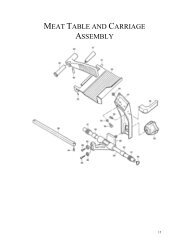
2.2 Assembly of Display Column<br />
1) You must follow the instructions in this section in order to assemble the Display Assembly properly.<br />
To begin the installation, make sure that the scale is unplugged from any electrical source. Your scale<br />
body has a display column bracket in the rear that the display column slides into. (See fig.)<br />
2) Hold the display assembly in front of you such that the display assembly forms the figure “7”.<br />
Next, with the scale’s keyboard facing you, insert the display column into the display bracket. When the<br />
display column reaches the bottom of the display bracket, you will “feel” the connectors “snap”<br />
together. (See fig.)<br />
3) Underneath the display bracket you will find 2 screw holes for the display assembly screws. Insert<br />
and fasten the 2 display assembly screws. You are done! (See fig.)<br />
5
3 Proper Operation<br />
3 Proper Operation<br />
3.1 Environmental Considerations & Safety<br />
1) Please avoid the following hostile conditions:<br />
Temperatures below or exceeding:<br />
-10º C ~ 40º C (14º F ~ 104º F)<br />
Ungrounded electrical outlet<br />
Excessive vibration Unstable or flimsy surface<br />
Wind or fans functioning in direct Shared electrical outlet<br />
contact with weighing platform.<br />
Direct sunlight Dust or dirt<br />
High humidity Poor ventilation<br />
2) Environmental Protection: The scale should be installed in a dry and liquid free environment. When<br />
the scale is installed in a high humidity or wet-type environment, be sure to avoid spilling or spraying<br />
directly on any surface of the scale.<br />
3) Personal Safety: It is extremely important to be aware of personal safety whenever maintaining or<br />
operating this equipment. Wherever possible, we have tried to place warning labels and other<br />
indicators at the actual location on the equipment where the danger is most likely to occur. However, it<br />
is not always possible to foresee all dangerous situations. Warnings and cautions that are necessary for<br />
the safe operation of the scale are contained in this manual. Please, make sure to carefully read ALL<br />
warnings and cautions before operating the scale.<br />
4) Observe the following safety precautions:<br />
Shut the scale OFF and unplug the scale whenever you are changing the label<br />
roll or whenever working in the printer bay.<br />
The outlet that the scale is plugged in to should be properly grounded.<br />
Whenever connecting or disconnecting ANY cables from the scale, be sure to<br />
hold the cables by the end connector. Failure to do so may cause a short circuit.<br />
Maintain a static free work area.<br />
Never use any other equipment on the same line: it should be a dedicated line.<br />
The outlet used must have the proper voltage ratings.<br />
6
3 Proper Operation<br />
3.2 Leveling and Location<br />
1) Location: This scale must be placed on a flat and stable surface. Please keep the scale away from<br />
the direct path of oscillating fans, ventilation systems, or strong drafts as these air disturbances can be<br />
picked-up by the scale’s very sensitive weighing platform and may cause incorrect weight readings.<br />
2) Leveling: If the scale is not properly leveled, please adjust the 4 adjustable legs at the bottom of<br />
the scale. Turn the legs clockwise or counterclockwise so as to center the bubble of the leveling gauge<br />
inside the indicated circle. Turning the adjustable legs counter-clockwise (viewed from top of scale) will<br />
lower that part of the scale. Turning the adjustable legs clockwise (viewed from top of scale) will raise<br />
that part of the scale. (See Fig.)<br />
7
3 Proper Operation<br />
3.3 Power Outlet and Requirements<br />
1) The <strong>LP</strong>-2 is designed to be used almost anywhere in the world! Like the many appliances of today,<br />
the <strong>LP</strong>-2 is designed with an automatically switching power supply. This allows operation when<br />
connected to an AC source from 85V to 240V at 50/60Hz with 5% tolerance.<br />
Remember: a switching power supply does not imply that bad, noisy, or improperly wired power lines<br />
will be problem free. With that in mind, please make sure that the power lines used for the <strong>LP</strong>-2 are<br />
dedicated lines with no high-noise devices (such as compressors, motors, etc) running on it. Also, make<br />
sure that the wiring to the electrical socket is correct. If you are uncertain as to the state of your<br />
business’ electrical lines, please contact a certified electrician.<br />
2) Once you are sure as to the safety of the electrical line, make sure to ONLY plug the scale into a 3-<br />
prong outlet. The third prong is a safety ground and an electrician should properly wire this if it is not<br />
correct or if you are unsure. Failure to this CAN result in electrical shock from use of this or any electronic<br />
scale.<br />
3) Do not use any 3-prong to 2-prong adapters or break-off the third prong from the <strong>LP</strong>-2 power cord.<br />
The third prong is necessary and must be properly connected.<br />
4) If you have any problems or questions regarding this matter, make sure to contact your authorized<br />
dealer or the CAS USA <strong>Service</strong> Department.<br />
Note: Be sure to check the <strong>LP</strong>-2’s serial number plate on the back of the scale for power specifications.<br />
8
4 Nomenclature<br />
4 Nomenclature<br />
4.1 Scale Overview<br />
1) Pictured below are important scale components and parts that you should be familiar with.<br />
# Description # Description # Description<br />
1 Advertisement Insert, rear 9 Fuse Cap 16 Power Switch<br />
2 Wireless Bridge Connector 10 Gauge, Leveling 17 Printer<br />
3 RS-232C 25 Pin Connector 11 Keyboard, Numeric 18 Serial Number Plate<br />
4 RS-232C 9 Pin Connector 12 Keyboard, Speed Keys 19 Side Access Door, Com port<br />
5 Ethernet Connector 13 Leveling Feet 20 Side Access Door, printer<br />
6 Display Column 14 Platform 21 Template Sheet, Numeric<br />
7 Display Window, customer 15 Platter 22 Template Sheet, PLU<br />
8 Display Window, user 23 Power Switch<br />
9
4 Nomenclature<br />
4.2 Display and Indicators<br />
1) VF Display: The front and rear displays on the <strong>LP</strong>-2 are dot matrix vacuum fluorescent displays.<br />
They will display all information pertinent to operating the scale.<br />
<strong>LP</strong>-2 Display Window: <strong>Sales</strong><br />
1 2 3 4 5 6 7<br />
17<br />
16<br />
Auto PrePack Shift Ride 12:12:00 PM<br />
I This is PLU Commodity Nam<br />
WEIGHT kg UNIT $ / kg TOTAL PRICE $<br />
ZERO ◀<br />
STABLE ○<br />
8<br />
15<br />
NET ◀<br />
0~30 lb x 0.01 lb / 30~60 lb x 0.02 lb, e=d=0.01 lb, 0.02 lb<br />
CAPACITY:<br />
0~15 kg x 0.005 kg / 15~30 kg x 0.01 kg, e=d=5g, 10g<br />
14 13 12 11 10 9<br />
# Description Values<br />
1 Mode indicator REG, RPK, MGR, ADD, PLU, NET1 , STR2 ,<br />
LOC, SET, X1, X2, Z1, Z2<br />
2 Print Mode indicator Auto<br />
3 Auto Clearing status indicator PrePack, Save, (Blank)<br />
4 Speed key Shift status indicator Shift, (Blank)<br />
5 Override, Frequent Shopper, &<br />
Discount Status<br />
Ride, FSP, DISC, Disc, 1, 2, 3, (Blank)<br />
6 Multi-function indicator Time, date, scale #, department #,<br />
Alt, Temporary Changes, (Blank)<br />
7 PLU Description line First non-blank line of PLU commodity<br />
8 Total price heading TOTAL PRICE and money symbol<br />
9 Total price indicator 7 digits USA: 0.00~9999.99<br />
10 Unit price heading UNIT, money and weigh symbols<br />
11 Unit price indicator 6 digits USA: 0.00~999.99<br />
12 Weight indicator 5 digits<br />
13 Weight heading WEIGHT and weigh symbol<br />
14 Negative weight indicator -, (Blank)<br />
15 Net-Weight indicator ◀, (Blank)<br />
16 Stable weight indicator ○, (Blank)<br />
17 Zero weight indicator ◀, (Blank)<br />
A Gross Zero indication is reached when the Net-Weight indicator is OFF, the Zero-Weight indicator is ON,<br />
the Stable indicator is ON, and the weight reads 0.00 or 0.000.<br />
10
4 Nomenclature<br />
4.3 Printer<br />
1) Pictured below are important printer components and parts that you should be familiar with.<br />
# Description # Description # Description<br />
1 Label/Paper Roll 7 Platen 13 Sensor Assembly, Gap<br />
2 Label Roll Spool 8 Pressure plate & width adjuster 14 Sensor Assembly, Peel-Off<br />
3 Lock-Down Tab 9 Pressure shaft 15 Shaft, Pick-Up Motor<br />
4 Paper Cutter 10 Release Lever, TPH 16 Side Access Door, printer<br />
5 Peel-Off Bar 11 Roller, return 17 Thermal Print Head<br />
6 Pick-Up Spool Assembly 12 Brush 18 Paper Guide Plate<br />
11
4 Nomenclature<br />
4.4 The Program Mode Numeric Key Pad<br />
Key Description<br />
0 ~ 9<br />
00<br />
.<br />
C<br />
COPY<br />
▲ ▼<br />
◀ ▶<br />
BACK<br />
SPACE<br />
O P COPY ▲<br />
L BACK<br />
Numeric keys. Used to enter programming data.<br />
Decimal key.<br />
Clear key. Used to clear erroneous entries and error conditions. Also stops<br />
multi-label printing that is in progress.<br />
Copy key.<br />
Up & Down arrow keys. Use to navigate through PGM mode.<br />
Left & Right arrow keys. Use to navigate through PGM mode.<br />
Backspace key. Used to backspace and delete text data.<br />
12<br />
PAGE<br />
UP<br />
SPACE ◀ SAVE ▶<br />
INSERT<br />
OVER DELETE PASTE<br />
7 8 9<br />
4 5 6<br />
1<br />
00<br />
.<br />
2 3<br />
0 C<br />
▼<br />
SHIFT<br />
ESC<br />
TEST<br />
ALT<br />
PAGE<br />
DOWN<br />
HE<strong>LP</strong><br />
LABEL<br />
FEED<br />
ENTER
4 Nomenclature<br />
Key Description<br />
PAGE<br />
UP<br />
PAGE<br />
DOWN<br />
A ~ Z<br />
INSERT<br />
OVER<br />
SAVE<br />
ENTER<br />
DELETE<br />
PASTE<br />
ALT<br />
SHIFT<br />
ESC<br />
HE<strong>LP</strong><br />
TEST<br />
LABEL<br />
FEED<br />
Page Up & Page Down keys. Use these to navigate 1 screen at a time.<br />
Alpha keys. Used to type text data.<br />
Insert/overwrite key. Used to toggle between Insert and overwrite modes for<br />
text typing.<br />
Save key. At any point in programming, this key saves your current data.<br />
Enter key. Used as an ENTER key.<br />
Delete key. Used to delete text data.<br />
Paste key.<br />
ALT key. This key is used for special key combination presses.<br />
SHIFT key. This is the Caps Lock key. It controls whether you are typing in<br />
uppercase .<br />
Escape key. This key toggles between Main menu and mode. It also<br />
is used to exit programs.<br />
Help key.<br />
Test key. Used to print test pattern, preview a scrolling message, and print a<br />
PLU verification label.<br />
Label Feed key. Use this key to feed labels or paper through printer.<br />
Carriage Return key. This key is used to insert Carriage Returns into the Text 1,<br />
2, & 3 fields of PLU Create/Edit.<br />
13
4 Nomenclature<br />
4.5 The Program Mode PLU Key Pad<br />
Q W E R T Y U I<br />
A S<br />
À<br />
à<br />
È<br />
è<br />
Key Description<br />
D F G H J K<br />
Z X C V B N M ,<br />
,<br />
|<br />
\<br />
@<br />
(<br />
CHANGE<br />
PRICE<br />
{<br />
[<br />
#<br />
)<br />
NEW<br />
PLU<br />
~<br />
A Z<br />
SPACE<br />
, ~ , <<br />
><br />
CHANGE<br />
PRICE<br />
NEW<br />
PLU<br />
EDIT<br />
PLU<br />
DELETE<br />
PLU<br />
}<br />
]<br />
^<br />
& %<br />
!<br />
Ì<br />
ì<br />
EDIT<br />
PLU<br />
Alpha keys. Used to type text data.<br />
Space bar.<br />
Special Symbol keys.<br />
PLU Price Change key.<br />
PLU Create key.<br />
PLU Edit key.<br />
PLU Delete key.<br />
SPACE<br />
Ñ<br />
ñ<br />
DELETE<br />
PLU<br />
$<br />
*<br />
Ò<br />
ò<br />
LIST<br />
PLUs<br />
14<br />
_<br />
-<br />
:<br />
;<br />
Ù<br />
ù<br />
PROGRAM<br />
SPEED KEYS<br />
+<br />
=<br />
“<br />
‘<br />
Ü<br />
ü<br />
PRINT<br />
TEST<br />
.<br />
.<br />
?<br />
/<br />
<<br />
><br />
ASSIGN<br />
SCROLL
4 Nomenclature<br />
Key Description<br />
LIST<br />
PLUs<br />
PGM<br />
SPEED KEYS<br />
PRINT<br />
TEST<br />
ASSIGN<br />
SCROLL<br />
PLU Listing key.<br />
Speed Key programming key.<br />
Print test key.<br />
Scrolling message assignment key.<br />
15
5 Getting Started<br />
5 Getting Started<br />
5.1 Installation of the Label Roll<br />
To install the label roll at ANY time you must follow the directions in this section:<br />
1) Press the ON/OFF key and make sure that the display is completely off. Open the printer’s sideaccess<br />
panel. As you can see, there is a detailed diagram affixed onto the inside of the side-access<br />
panel. Use this diagram (or this manual) for future reference on how to properly install the label roll.<br />
(See fig.)<br />
2) Find and remove the Pick-Up Spool assembly and the label-roll Pin. Also, find the Print Head Release<br />
Lever and push it in the direction indicated. The print head will be in the “UP” position. If there were any<br />
labels previously installed please remove all the collected backing paper from the Pick-Up Spool<br />
assembly. The Pick-Up Spool assembly automatically collapses when it is removed from the Pick-Up<br />
shaft. This makes the removal of the backing paper very simple. Also remove the cardboard paper roll<br />
core if there was a label roll previously installed. (See fig.)<br />
16
5 Getting Started<br />
3) Take the new roll of labels and find the ending. Peel-off and discard about one foot (12 inches) of<br />
labels from the backing before installing the roll into the scale. Place the label in the scale as shown<br />
and thread the backing through the appropriate places. (See fig.)<br />
4) Please view the checkpoints on the diagram below as you read these directions to thread the labels.<br />
Feed the backing paper over the width-adjusting Pressure Shaft lifting the Pressure Plate in order to<br />
place the backing between the two making sure that the width adjustment is as exact as possible<br />
without bending the backing paper.<br />
Feed the backing paper inside the slot between the Gap sensor assembly making sure that the labels<br />
travel under the Secondary width-adjuster.<br />
Make sure that labels are pushed all the way to the left on the Peel-Off bar.<br />
Feed the backing over the Rubber Roller and under the Print Head being careful not to touch the<br />
underside of the Print Head.<br />
Continue to feed the backing paper over the Peel-off Bar.<br />
Continue to feed it under the Return Roller.<br />
Feed the backing under and around the Pick-Up Shaft.<br />
Now attach the Pick Up Spool assembly onto the Pick-Up Shaft and turn it slowly counterclockwise in<br />
order to tighten the backing paper.<br />
5) Push the Print Head down in order to lock it back in place. You will feel and hear it lock in place.<br />
Close the printer access panel and press the ON/OFF key. You have completed the label roll installation.<br />
(See fig.)<br />
17<br />
MAKE SURE YOU HAVE DONE<br />
THE ADJUSTMENTS AT POINTS<br />
1, 2, AND 3 BEFORE YOU LOCK<br />
THE PRINT HEAD.
5 Getting Started<br />
5.2<br />
Menu and Data Entry System<br />
To Enter Calibration Menu, hold<br />
down the ON/OFF key while turning<br />
on the power<br />
The<br />
CAL Main Menu screen looks<br />
like this:<br />
Pressing ESC from this menu<br />
w ill take you out of CAL mode and<br />
effect all of the changes that you<br />
may have made.<br />
18<br />
< CAL: MAIN MENU ><br />
1. CALIBRATION 5. NETWORK OPTIONS<br />
2. SYSTEM OPTIONS 6. SELF TEST<br />
3. DIGITAL FILTERING 7. NORMAL FUNCTION<br />
4. PRINTER SETTINGS 8. PRICE OPTIONS<br />
M enus & Sub-Menus: Any menu or sub-menu screen that you access can be exited by pressing the ESC<br />
key. This will take you back to any previous menu or sub-menu except if you press ESC from the CAL<br />
Main Menu. The picture above is an example of a menu. Any menu that you access by selecting<br />
options 1 to 5 will be a sub-menu of CAL Main Menu. Any menu that you access from a sub-menu will<br />
be a sub menu of that menu, etc. This way you can always backtrack to the CAL Main Menu by<br />
pressing the ESC.<br />
E ntry Screens: An example of an<br />
entry screen is shown here. If you<br />
access an entry screen you can<br />
NUMERIC<br />
< CAL: SAMPLE ENTRY SCREEN ><br />
exit it without making changes by<br />
pressing the ESC key. This will Unit :[1] 0)kg 1)lb<br />
have the effect of returning to the<br />
previous screen, menu, or submenu,<br />
whatever be the case. If<br />
you are on an entry screen you<br />
can save & exit that screen by<br />
Label Format (1-999):[123] LST #8020 Ingredient<br />
Unit Price :$[ 0.99] / lb<br />
pressing the SAVE key at any point.<br />
Pressing the ENTER key while the cursor is on the last field (bottom)<br />
of an entry screen will have the same effect as pressing the SAVE key.<br />
F ields (on-screen): Entry screens have fields that contain data that you can modify. This data is always<br />
contained in brackets: [123456] or [ABCDEDG ]. To select a field, simply use the ↑ or ↓ keys to<br />
move the cursor to that field.<br />
• A field’s name followed by a colon will usually appear on the left side of the bracketed data. In<br />
the Sample Entry Screen above, the word “Unit :” appears to the left of the brackets containing the<br />
value 1. To the right of the Unit field is the options that you may select: 0 is kilograms & 1 is pounds.<br />
These are the only two acceptable values for this field. Any values selected outside that range will<br />
automatically replaced with values within that range.<br />
• The Label Format Field is slightly different. This field<br />
indicates its range in parenthesis listed after<br />
the field’s<br />
name. In this case it is 1 to 999. Also, the data that appears to the right of the entry field<br />
brackets changes dynamically as you type. For example, if the cursor is on the Label Format field and<br />
you press the CLEAR key you will see that the format number will change to 1 and the name of label 1<br />
will appear on the right side of the brackets. If you press the 1 key & then the 2 key, then the name of<br />
label 12 will appear. If you now press the 3 key then the name of label 123 will appear.<br />
• The Unit Price field tells you that the values are in 2 decimal place format and that this is a $<br />
va lue. The right side shows “ / lb” which means that this is a $ per pound field.
5 Getting Started<br />
< Calibration Mode Diagram ><br />
CALIBRATION(MENU) C1 CALIBRATION<br />
C11<br />
C12<br />
C13<br />
C14<br />
19<br />
SPAN CALIBRATION<br />
SPAN/ZERO FINE ADJUST<br />
GRAVITY CONSTANT<br />
CAPACITY & UNITS<br />
C2 SYSTEM OPTIONS<br />
C21 WEIGHT OPTIONS<br />
C3<br />
C4<br />
C5<br />
C6<br />
C7<br />
C8<br />
DIGITAL FILTERING<br />
PRINTER SETTINGS<br />
NETWORK OPTIONS<br />
SELF TEST<br />
NORMAL FUNCTION<br />
PRICE OPTIONS<br />
C22<br />
C23<br />
C24<br />
C25<br />
C41<br />
C42<br />
C43<br />
C44<br />
C45<br />
C46<br />
C47<br />
C61<br />
C62<br />
C63<br />
C64<br />
C65<br />
C66<br />
C67<br />
C68<br />
C69<br />
STEP1 STEP2 STEP3<br />
NON-WEIGHT OPTIONS<br />
KEYPAD OPTIONS<br />
CLEAR MEMORY<br />
SELECT COUNTRY<br />
PRINTER SENSORS<br />
PRINT SPEED<br />
PRINTER ODOMETER<br />
LABEL TYPE<br />
ADJUST FEED LENGTH<br />
AUTO THRESHOLD<br />
REPORT SETTINGS<br />
DISPLAY<br />
LOADCELL<br />
KEYBOARD<br />
PRINTER<br />
PEEL-OFF<br />
MEMORY SIZE<br />
NV MOMORY TEST<br />
SERIAL TEST<br />
FIRMWARE VERSIONS<br />
C211<br />
C212<br />
C213<br />
C214<br />
C221<br />
C222<br />
C223<br />
C241<br />
C242<br />
C243<br />
C244<br />
CAPACITY & UNIT<br />
TARE OPTIONS<br />
ZERO RANGE<br />
CAPTIONS, HEADINGS<br />
DECIMAL SETTING<br />
AUTO THRESHOLD<br />
REPORT SETTINGS<br />
NON-VOLATILE MEMORY<br />
STATIC RAM<br />
EEPROM<br />
ALL MEMORY
6 Calibration Mode<br />
6 Calibration Mode<br />
6.1 Entering Calibration Mode<br />
1. Make sure that the Main Power is OFF (switch on left side of scale.)<br />
2. Press and hold down the ON/OFF key on the upper right corner of the keyboard.<br />
3. While you are holding down the ON/OFF key, turn the Main power ON.<br />
4. Once you here a series of “chirps” release the ON/OFF key.<br />
5. After a few seconds the scale will be in CAL mode.<br />
The CAL Main Menu<br />
screen will appear as follows:<br />
Pressing ESC from this<br />
menu will take you out of CAL<br />
mode and affect all of the<br />
changes that you may have<br />
made.<br />
20<br />
< CAL: MAIN MENU ><br />
1. CALIBRATION 5. NETWORK OPTIONS<br />
2. SYSTEM OPTIONS 6. SELF TEST<br />
3. DIGITAL FILTERING 7. NORMAL FUNCTION<br />
4. PRINTER SETTINGS 8. PRICE OPTIONS<br />
NOTE: Only CAS trained personnel should attempt to make changes in CAL mode. If you are not<br />
trained to work on this equipment, please contact the CAS (USA) <strong>Service</strong> Department for assistance.<br />
Non-qualified personnel attempting service the CAS <strong>LP</strong>-2, risk void the scale’s warrantee.<br />
ALL OF THE SCREENS TO FOLLOW SHOW USA DEFAULT SETTINGS.<br />
6.1A Entering Calibration Mode (alternate method)<br />
Some units have a working calibration switch located on the top of the upper case, underneath<br />
the platter. Although USA models may have CAL switches in this location, these switches do not have<br />
any effect. If your scale has a working CAL switch, then you must seal the scale physically.
7 Calibrating the Scale<br />
7 Calibrating the Scale<br />
7.1 Calibration Menu<br />
Once at the CAL Main Menu<br />
screen, press the 1 key.<br />
The Calibration Menu screen will<br />
appear as follows:<br />
Span Calibration: Requires the<br />
use of weights. The display will<br />
indicate the amount of weight<br />
that you will need. <strong>LP</strong>-2 VER 1.03<br />
or higher USA models will need 60<br />
21<br />
< CAL: CALIBRATION MENU ><br />
1. SPAN CALIBRATION (60 lb)<br />
2. SPAN/ZERO FINE ADJUST<br />
3. GRAVITY CONSTANT<br />
4. CAPACITY & UNITS<br />
ZERO CALIBRATION<br />
1. Remove all weight from the platter.<br />
2. Press ENTER when ready.<br />
SPAN CALIBRATION<br />
< CAL: MAIN MENU ><br />
1. CALIBRATION 5. NETWORK OPTIONS<br />
2. SYSTEM OPTIONS 6. SELF TEST<br />
3. DIGITAL FILTERING 7. NORMAL FUNCTION<br />
4. PRINTER SETTINGS 8. PRICE OPTIONS<br />
lbs. to calibrate. You will need the full capacity. If kilo weights are required the scale will display 30 kg.<br />
Span Fine Adjust: Does not require weights but they are recommended for checking the Fine<br />
Adjustment.<br />
Gravity Constant: This is a value that causes automatic compensation for different altitudes. If the scale<br />
is calibrated in NY and shipped to CA, you can simply enter the Gravity Constant for CA and the scale<br />
will be calibrated for CA even though it was calibrated in NY.<br />
CAPACITY & UNITS: Same as the 8.1.1. Refer to that.<br />
7.2 Span Calibration<br />
Once at the CAL Main<br />
Menu screen, press the 1 key. The<br />
Calibration Menu screen will<br />
appear. Press the 1 key from the<br />
Calibration menu screen to select<br />
Span Calibration. The first Span<br />
Calibration screen will appear as<br />
follows:<br />
Once you press the ENTER<br />
key, the scale checks the zero<br />
weight and stability. If the scale is<br />
unstable or there is excessive<br />
weight on the platter the ZERO<br />
Calibration will fail and will then<br />
0 3569<br />
1. Place 60 lb on the platter.<br />
2. Press ENTER when ready.<br />
0 3569<br />
be repeated. If all is well the second Span calibration screen will appear as follows:
7 Calibrating the Scale<br />
Place 60 lbs. on the platter. Once<br />
the weight is stable, press ENTER<br />
key. Then the scale checks<br />
stability & the span weight. If the<br />
SPAN calibration is successful, the<br />
Calibration Passed screen will be<br />
displayed temporarily and then<br />
return to the Calibration screen.<br />
Calibration Passed!<br />
If there is a problem, you will get the “Calibration Failed!” message and will go back to the Calibration<br />
Menu screen. If you get this message, please check the following:<br />
• You are using 60 lb of certified weights.<br />
• The scale has prompted you for 60 lb and not 30 kg or any other capacity.<br />
• The weight/counts were stable throughout the calibration process (+ 5 count ∆).<br />
• There is nothing obstructing the platter & the platter is mounted properly onto the platform.<br />
• You are using the correct platter and/or correct dead load (IZR* is 10% of capacity.)<br />
• Try process again 2 more times always following the onscreen directions.<br />
If problems persist, you may have a damaged: A/D Converter (90%).<br />
If problems persist, you may have a damaged: Load Cell (5%).<br />
Contact the CAS <strong>Service</strong> Department: Other (5%).<br />
NOTE: Any changes made here will affect the NTEP Audit Trail counters (CAL counter only.)<br />
*IZR: Initial Zero Range allows +10%-of-Capacity from Calibrated Zero point.<br />
7.3 Span/Zero Fine Adjust<br />
Once at the CAL Main<br />
Menu screen, press the 2 key. The<br />
display will read “Checking Load<br />
Cell…” and then the Span Fine<br />
Adjust screen will appear as<br />
follows:<br />
NUMERIC<br />
< CAL: SPAN/ZERO FINE ADJUST ><br />
SPAN: [ 74062]<br />
ZERO: [ 3566]<br />
WEIGHT: 0.000 lb<br />
TEST = Weighing Mode<br />
SAVE = SAVE, ESC= UNDO CHANGES<br />
WEIGHT: The Weight display will be shown in calibrated units (lb if you calibrated in lb, kg if you<br />
calibrated in kg.) The weight is in 1/60,000 resolution and updates a bit more slowly than in REG mode.<br />
You can use this mode to verify different weigh points. Remember that the REG mode weight display<br />
will round up to the nearest 1/3000 division.<br />
SPAN: The Span value is the measurement in counts of the full load. Increasing the span will display<br />
a lesser weight for a given mass; decreasing the span will display a greater weight for the same mass.<br />
After you change the span value, while the cursor is on the Span field, you need to press the ENTER key<br />
twice in order to refresh the weight display.<br />
22
7 Calibrating the Scale<br />
ZERO: The Zero value is the current Zero value for the scale. It should be +10% from the calibrated<br />
zero; however, if you change and save this value, it becomes the calibrated zero value. While the<br />
cursor is on the Zero field, you can change this value but, you must press the ENTER key twice for it to<br />
take effect. Lowering the value will lower the weight; increasing the value will increase the weight.<br />
While the cursor is on the Zero field, can also press the TEST key to bring the weight to 0.000. This also has<br />
the effect of changing the Zero value.<br />
If you wish to save your changes, press the SAVE key at any time or the ENTER key while the<br />
cursor is on the last field of the screen. If you wish to undo your changes, press the ESC key at anytime.<br />
Once you leave this screen, the display will return to the previous screen (Calibration Menu.)<br />
NOTE: Any changes made here will affect the NTEP Audit Trail counters (CAL counter only.)<br />
7.4 Gravity Constant<br />
Once at the Main menu<br />
screen, press the 3 key. The<br />
Gravity Constants screen will<br />
appear:<br />
23<br />
NUMERIC<br />
< GRAVITY CONSTANTS ><br />
At Calibration Place : 9.7994<br />
At Using Place : [9.8024]<br />
If the Calibration Place & the<br />
Using Place values are the same,<br />
it means that the scale was<br />
calibrated at that constant’s corresponding location(s) and thus no compensation takes place. If these<br />
are different, this implies that the scale was calibrated at some other location than the Using Place<br />
value. In this case compensation takes place.<br />
The purpose of this function is to allow you to calibrate the scale in one location, say New York, and<br />
then ship it to another location, say Panama, where you change the Using Place value from 9.8024 to<br />
9.7814. This will compensate for the difference in gravity at the 2 locations and so you need not<br />
recalibrate the scale. Press ENTER or SAVE to save changes or ESC to quit without changing.<br />
Use the following table to determine the proper G-Constant for your<br />
area.<br />
Country City G-Constant Country City G-Constant<br />
Argentina Buenos Aires 9.7979 Mexico Mexico City 9.7799<br />
Australia Sydney 9.7979 Morocco Rabat 9.7964<br />
Austria Vienna 9.8099 Netherlands Amsterdam 9.8129<br />
Belgium Brussels 9.8114 New Zealand Wellington 9.8039<br />
Belize Manamah 9.7904 Norway Oslo 9.8189<br />
Bolivia La Paz 9.7844 Panama Panama City 9.7814<br />
Brazil Brasilia 9.7889 Peru Lima 9.7829<br />
Canada Montreal 9.8069 Philippines Manila 9.7844<br />
Ottawa 9.8069 Poland Swider 9.8159<br />
Toronto 9.8054 Portugal Lisbon 9.8009<br />
Vancouver 9.8099 Rumania Bucharest 9.8054<br />
Check Republic Prague 9.8114 Saudi Arabia Riyad 9.7904<br />
Chile Santiago 9.7979 Scotland Stockholm 9.8189<br />
China Hong Kong 9.8099 Singapore Singapore 9.7814<br />
Colombia Bogota 9.7799 South Africa Johannesburg 9.7919<br />
Costa Rica San Jose 9.7829 Spain Madrid 9.8024<br />
Cypress Nicosia 9.7979 Switzerland Bern 9.8084
7 Calibrating the Scale<br />
Denmark Copenhagen 9.8159 Taiwan Taipei 9.7904<br />
Ecuador Quito 9.7724 Tunisia Tunis 9.7799<br />
Finland Helsinki 9.8189 Turley Ankara 9.8024<br />
Germany Dusseldorf 9.8129 Uruguay Montevideo 9.7964<br />
Great Britain London 9.8144 USA<br />
Anchorage 9.8189<br />
Greece Athens 9.8009 Atlanta 9.7964<br />
Guatemala Guatemala City 9.7844 Boston 9.8039<br />
Hungary Budapest 9.8069 Chicago 9.8024<br />
Indonesia Djakarta 9.7814 Dallas 9.7949<br />
Iraq Baghdad 9.7964 Detroit 9.8039<br />
Japan Mishima 9.7979 Los Angeles 9.7979<br />
Korea Seoul 9.7994 New York 9.8024<br />
Kuwait Kuwait 9.7919 Philadelphia 9.8024<br />
Lebanon Beirut 9.7964<br />
San Francisco 9.7994<br />
Mauritius Port Louis 9.7859 Venezuela Caracas 9.7829<br />
NOTE: The G-Constant is the acceleration of gravity in meters per second per second.<br />
NOTE: Any changes made here will affect the NTEP Audit Trail counters (CAL counter only.)<br />
24
8 System Options<br />
8 System Options<br />
8.1 Weight Options<br />
Once at the CAL Main<br />
menu screen, press the 2 key.<br />
The System Options Menu screen<br />
will appear as follows. At the<br />
System Options Menu screen,<br />
press the 1 key for Weight Options.<br />
The Weight Options Menu<br />
screen will appear as follows:<br />
8.1.1 Capacity & Units<br />
Once at the Weight Options<br />
Menu screen, press the 1 key for<br />
Capacity & Units. The Capacity &<br />
Units screen will then appear as<br />
follows:<br />
25<br />
< CAL: SYSTEM OPTIONS ><br />
1. WEIGHT OPTIONS<br />
2. NON-WEIGHT OPTIONS<br />
3. KEYPAD OPTIONS<br />
4. CLEAR MEMORY<br />
5. SELECT COUNTRY<br />
< CAL: WEIGHT OPTIONS ><br />
1. CAPCITY & UNITS<br />
2. TARE OPTIONS<br />
3. ZERO RANGE<br />
4. CAPTIONS & HEADINGS<br />
NUMERIC<br />
< CAL: CAPACITY & UNITS ><br />
Unit :[1]<br />
0)kg 1)lb<br />
Capacity :[1] 0)15 1)30 2)60<br />
Weigh Range :[1] 0)Single 1)Dual<br />
Unit: This determines the unit that<br />
you will use to calibrate the scale<br />
and it is the default unit that the s-cale will turn ON to when it goes into <strong>Sales</strong> mode. If you change this<br />
value without re-calibrating the scale, you will get a “Calibrated Mass Error” every time you power ON<br />
the scale.<br />
Capacity: This determines the capacity for the scale. The <strong>LP</strong>-2 VER 1.03-USA is available in 60 lb/ 30 kg<br />
only; however, the scale is programmable for 30 lb, 60 lb, 15 kg, or 30 kg.<br />
Weigh Range: This determines the range for the scale & thus determines the minimum displayed<br />
divisions. See chart below.<br />
Capacity Weight Range (Single) Weight Range (Dual)<br />
6 kg 0.000 kg ~ 6.000 kg X 0.002 kg (2 g) 0.000 kg ~ 2.999 kg X 0.001 kg (1 g)<br />
3.000 kg ~ 6.000 kg X 0.002 kg (2 g)<br />
15 kg 0.000 kg ~ 15.000 kg X 0.005 kg (5 g) 0.000 kg ~ 5.998 kg X 0.002 kg (2 g)<br />
6.000 kg ~ 15.000 kg X 0.005 kg (5 g)<br />
30 kg 0.00 kg ~ 30.00 kg X 0.01 kg (10 g) 0.000 kg ~ 14.995 kg X 0.005 kg (5 g)<br />
15.000 kg ~ 30.00 kg X 0.01 kg (10 g)<br />
15 lb 0.00 lb ~ 15.00 lb X 0.005 lb 0.000 lb ~ 7.498 lb X 0.002 lb<br />
7.500 lb ~ 15.000 lb X 0.005 lb<br />
30 lb 0.00 lb ~ 30.00 lb X 0.01 lb 0.000 lb ~ 14.995 lb X 0.005 lb<br />
15.000 lb ~ 30.00 lb X 0.01 lb<br />
60 lb 0.00 lb ~ 60.00 lb X 0.02 lb 0.00 lb ~ 29.99 lb X 0.01 lb<br />
30.00 lb ~ 60.00 lb X 0.02 lb<br />
NOTE: Any changes made here will affect the NTEP Audit Trail counters (OPT counter only.)
8 System Options<br />
8.1.2 Tare Options<br />
Once at the Weight Options<br />
Menu screen, press the 2 key for<br />
Tare Options. The Tare Options<br />
screen will appear as follows. This<br />
is what the screen looks like when<br />
the cursor is on the Tare field.<br />
26<br />
NUMERIC<br />
< CAL: TARE OPTIONS ><br />
Tare :[0] 0. Full Tare<br />
Tare Mode :[0] 1. Half Tare<br />
2. Custom Tare<br />
Tare: This determines the Tare’s<br />
maximum capacity.<br />
• Full tare will allow you tare up to the max capacity of the scale.<br />
• Half tare will allow you to tare up to lower value of the upper range (see chart on previous<br />
page.)<br />
• Custom tare allows you to specify the maximum tare value.<br />
Tare Mode: This determines how<br />
the Tare operates. The screen will<br />
change as follows when the<br />
cursor is on the Tare Mode field.<br />
• One time tare allows you<br />
to enter a tare once (manual or<br />
platter tare) and then you must<br />
clear that tare before you can<br />
enter a new one.<br />
NUMERIC<br />
< CAL: TARE OPTIONS ><br />
Tare :[0] 0. One Time Tare<br />
Tare Mode :[0] 1. Successive Tare<br />
• Successive tare allows you to combine platter tares. For example, you can place 5 lb on the<br />
scale and press TARE; put another 5 lb and press TARE; put another 5 lb and press TARE to get a<br />
combined tare of 15 lb.<br />
Maximum Tare: This field only<br />
comes up when the Tare field is<br />
set to 2 and you press ENTER or ↓<br />
from the Tare Mode field. The<br />
screen appears as follows. The<br />
Maximum tare determines the<br />
Tare’s maximum capacity.<br />
NUMERIC<br />
< CAL: TARE OPTIONS ><br />
Tare :[2]<br />
Tare Mode :[0]<br />
Maximum Tare :[60.000] lb<br />
NOTE: Any changes made here will affect the NTEP Audit Trail counters (OPT counter only.)<br />
8.1.3 Zero Range<br />
Once at the Weight Options<br />
Menu screen, press the 3 key for<br />
Zero Range. The Zero Range<br />
screen will then appear.<br />
NUMERIC<br />
< CAL: ZERO RANGE ><br />
Initial Zero Range(+,-) :[10]%<br />
ReZero Range (+,-) :[5]%<br />
Initial Zero Range: This is an<br />
allowable range from Calibrated<br />
Zero that the scale will go to zero from at start up. The range is CZP + ((CAPACITY x IZR) / 100) x
8 System Options<br />
CPD, where CZP = Calibrated Zero Point in counts, IZR is the Initial Zero Range value, & CPD is a<br />
conversion factor called Counts Per Division.<br />
ReZero Range: This is an allowable range from Initial Zero that the scale will go to zero from when you<br />
press the ZERO key. The range is IZ + ((CAPACITY x RZR) / 100) x CPD, where IZ = Initial Zero Point in<br />
counts, RZR is the ReZero Range value, & CPD is a conversion factor called Counts Per Division.<br />
NOTE: Any changes made here will affect the NTEP Audit Trail counters (OPT counter only.)<br />
8.1.4 Captions & Headings<br />
For changes to Captions or Headings please consult your Authorized CAS Dealer. These changes are<br />
only possible through <strong>Service</strong> Programming:<br />
< SET: CAPTIONS & HEADINGS ><br />
1.LABEL CAPTIONS<br />
2.DISPLAY HEADINGS<br />
The Label Captions options allow you to specify some of the Captions that get printed. An example of<br />
a Caption is “TOTAL PRICE $” which usually appears above the Total Price box on some formats. These<br />
need to change dynamically when toggling between weighing units (lb/kg).<br />
The Display Headings options allow you to specify some of the wording that appears on the<br />
REG/MGR/RPK display. These include “TOTAL PRICE $” , “PRICE lb/$”, etc. These too need to change<br />
dynamically when toggling between weighing units (lb/kg).<br />
27
8 System Options<br />
The Label Captions screens are very similar varying only in the defaulting data.<br />
INS/CAPS<br />
(1/4)< SET: LABEL CAPTIONS CURRENCY ><br />
Total Price: [TOTAL PRICE $ ]<br />
By-Count Price: [QTY / $ ]<br />
By-Weight lb Price: [PRICE $/lb ]<br />
By-Weight kg Price: [PRICE $/kg ]<br />
Tare lb: [TARE lb ]<br />
INS/CAPS<br />
(2/4)< SET: LABEL CAPTIONS CURRENCY ><br />
Tare kg: [TARE kg ]<br />
Discount Price: [TAX $ ]<br />
Regular Price: [REG PRICE ]<br />
Tax Price: [TAX $ ]<br />
Packed on Date: [PACKED ON ]<br />
INS/CAPS<br />
(3/4)< SET: LABEL CAPTIONS CURRENCY ><br />
Sell By Date: [SELL BY ]<br />
Cook By Date: [COOK BY ]<br />
Count: [COUNT ]<br />
FSP Unit Price: [SAVE UNIT PRICE ]<br />
FSP Total Price: [SAVE TOTAL PRICE ]<br />
INS/CAPS<br />
(4/4)< SET: LABEL CAPTIONS CURRENCY ><br />
FSP Saving: [SAVING ]<br />
FSP Price Text: [SAVE MORE PRICE ]<br />
FSP Saving Text: [YOU SAVE ]<br />
Remember that you can press SAVE at any time in order to save the current screen contents and return<br />
to the previous menu. The ESC key exits and returns to the previous menu.<br />
28
8 System Options<br />
The Display Headings screens are very similar; however, Display -Headings has one more screen than<br />
INS/CAPS<br />
(1/2)< SET: DISPLAY HEADINGS ><br />
Currency Symbol: [$ ]<br />
Total Price Box: [TOTAL PRICE $]<br />
By-Weight lb Unit Price: [UNIT $ / lb]<br />
By-Weight kg Unit Price: [UNIT $ / kg]<br />
By-Count Unit Price: [ PCS / $ ]<br />
INS/CAPS<br />
(2/2)< SET: DISPLAY HEADINGS ><br />
Weight lb: [WEIGHT lb ]<br />
Weight kg: [WEIGHT kg ]<br />
Quantity Sold: [QTY ]<br />
By-Count Net Weight: [Net Wt. ]<br />
8.2 Non-Weight Options<br />
Once at the CAL Main menu screen, press<br />
the 2 key. The System Options Menu<br />
screen will appear as follows. At the<br />
System Options Menu screen, press the 2<br />
key for Non-Weight Options.<br />
The Non-Weight Options Menu screen will<br />
appear as follows:<br />
8.2.1 Decimal Place Setting<br />
You can determine the decimal place<br />
setting.<br />
29<br />
Currency 1 screen 1 of 2.<br />
Currency 1 screen 2 of 2.<br />
< CAL: SYSTEM OPTIONS ><br />
1. WEIGHT OPTIONS<br />
2. NON-WEIGHT OPTIONS<br />
3. KEYPAD OPTIONS<br />
4. CLEAR MEMORY<br />
5. SELECT COUNTRY<br />
< CAL: NON-WEIGHT OPTIONS ><br />
1. DECIMAL PLACE SETTING<br />
2. AUTO PRINT THRESHOLD<br />
3. REPORT SETTINGS<br />
NUMERIC<br />
< CAL: DECIMAL PLACE SETTINGS ><br />
Price Decimal Place (0~4) :[2] 0.00<br />
Decimal Symbol (0~1) :[1] 0.00<br />
Total Price Max Digits (0~1) :[0] 6, 7
8 System Options<br />
8.2.2 Auto Print Threshold<br />
Once at the Non-Weight Options Menu screen, press the 3 key for Auto Print Threshold. The Auto Print<br />
Threshold screen will then appear as follows:<br />
Min Weight: This determines how much the<br />
weight must deviate in order for PRE PACK to<br />
automatically print a label. This value is in<br />
divisions so on a 60 lb x 0.02lb Single range <strong>LP</strong>-2,<br />
a value of 2 will cause an auto print if the weight<br />
deviates by ( 2 X 0.02 lb ) = 0.04 lb. Remember,<br />
it must deviate by this much weight and then<br />
stabilize before it can print.<br />
8.2.3 Report Settings<br />
Once at the Non-Weight Options<br />
Menu screen, press the 4 key for<br />
Report Settings. The Report<br />
Settings screen will then appear as<br />
follows:<br />
30<br />
NUMERIC<br />
< CAL: AUTO PRINT THRESHOLD ><br />
Minimum Weight for Auto Print: [ 2]div<br />
NUMERIC<br />
IC<br />
< CAL: REPORT SETTINGS ><br />
Print Null <strong>Sales</strong>? (Y/N) :[N]<br />
Disable Takeup Motor? (Y/N) :[Y]<br />
Auto Print Verify Labels? (Y/N) :[N]<br />
Print Null <strong>Sales</strong>: This determines<br />
whether all PLUs get reported (Y) or only active PLUs with sales get reported on (N). If you have 1000<br />
PLUs programmed but only used 200 of them you might not want to get a report with 800 lines of zero<br />
sales and then 200 lines of active sales.<br />
Disable Takeup Motor: If Y then when you print sales reports the backing paper will not be taken up. If<br />
N then when sales reports are printed the backing paper is collected. Remember, this feature is only<br />
active for Label Type 0 & 1. Label Type 2 always has the take up motor inactive.<br />
8.3 Keypad Options<br />
Once at the CAL Main menu<br />
screen, press the 2 key. The<br />
System Options Menu screen will<br />
appear as follows. At the System<br />
Options Menu screen, press the 3<br />
key for Keypad Options & the<br />
Keypad Options screen will<br />
appear.<br />
The Keypad Options<br />
screen will appear as follows:<br />
This screen has 2 pages, as you<br />
can see from the 1/2 page<br />
indicator at the top left of the<br />
screen.<br />
< CAL: SYSTEM OPTIONS ><br />
1. WEIGHT OPTIONS<br />
2. NON-WEIGHT OPTIONS<br />
3. KEYPAD OPTIONS<br />
4. CLEAR MEMORY<br />
5. SELECT COUNTRY<br />
INS/CAPS<br />
(1/2) < CAL: KEYPAD OPTIONS ><br />
LB/KG Key Allowed ? (Y/N) :[Y]<br />
1/2 & 1/4 Keys Allowed ? (Y/N) :[Y]<br />
100g Key Allowed ? (Y/N) :[Y]<br />
ADD Key Allowed ? (Y/N) :[Y]<br />
TARE Key Allowed ? (Y/N) :[Y]
8 System Options<br />
The second screen looks like this:<br />
lb/kg key: If you set this to Y then<br />
the lb/kg key will work in sales<br />
mode and allow you to switch<br />
between lb & kg modes. If you<br />
set this to N then you will not be<br />
allowed to switch between lb &<br />
kg modes.<br />
INS/CAPS<br />
(2/2) < CAL: KEYPAD OPTIONS ><br />
Numeric Tare Allowed ? (Y/N) :[Y]<br />
Double Zero Key Allowed ? (Y/N) :[Y]<br />
Misc PLU Keys Allowed ? (Y/N) :[Y]<br />
PLU Unit Conversion Allowed ? (Y/N) :[Y]<br />
Remember the scale will only work in the calibrated unit when this option is N. Also, PLUs programmed<br />
for a unit other than the calibrated unit will not be accessible when this option is N. This means that if<br />
this option is set to N and the scale was calibrated in kg, then only kg PLUs will work and the scale will<br />
only weigh in kg.<br />
1/2, 1/4, & 100g keys: If this is set to Y then these keys will in sales mode (1/2 & 1/4 in lb mode.) If this<br />
option is set to N, then these keys will not work in any mode. Remember, some states require that these<br />
keys be disabled.<br />
ADD key: The ADD key is used to combine multiple sales onto 1 label while still issuing individual labels.<br />
If this is set to Y then the ADD key will be operational. If this option is set to N, then the ADD key will not<br />
be operational.<br />
TARE key: The TARE key is used to enter tares manually (using 0 ~ 9 keys to enter tare weight) and platter<br />
tare (placing empty container on the platter). If this is set to Y then the TARE key will be operational. If<br />
this option is set to N, then the TARE key will not be operational & only PLU programmed tares will be<br />
allowed.<br />
Numeric Tare: If this is set to Y then the TARE key will allow manual tares. If this option is set to N, then<br />
the TARE key will not allow manual tares (using 0 ~ 9 keys to enter tare weight.)<br />
00 key: If this is set to Y then the 00 key will work the same as pressing the 0 key twice. If this option is set<br />
to N, then the 00 key will not work at all (do nothing.)<br />
Misc PLU keys: If this is set to Y then the 3 Misc PLU keys will work. If this option is set to N, then the 3 Misc<br />
PLU keys will not work as Misc PLU keys; instead they will operate as Speed Keys 54, 55, & 56 (unshifted) &<br />
110, 111, & 112 (shifted) respectively.<br />
PLU Unit Conversion: If this is set to Y then PLUs programmed will be switched from pound to metric<br />
weighing.<br />
< CAL: SYSTEM OPTIONS ><br />
8.4 Clear Memory<br />
Once at the CAL Main menu screen,<br />
press the 2 key. The System Options<br />
Menu screen will appear as follows. At<br />
the System Options Menu screen, press<br />
the 4 key for Clear Memory.<br />
31<br />
1. WEIGHT OPTIONS<br />
2. NON-WEIGHT OPTIONS<br />
3. KEYPAD OPTIONS<br />
4. CLEAR MEMORY<br />
5. SELECT COUNTRY<br />
< CAL: CLEAR MEMORY ><br />
1. NON-VOLATILE MEMORY<br />
2. STATIC RAM<br />
3. EEPROM<br />
4. ALL MEMORY
8 System Options<br />
The Clear Memory Menu screen will appear as follows:<br />
Non-Volatile Memory: This is where all of your PLU data, label formats (100 ~ 999), and non-CAL mode<br />
settings are stored. Erasing this memory will lose all PLU, Label formats 100 to 999, and non-CAL mode<br />
options.<br />
Static RAM: This is where all of your PLU sales data & the scale’s Runtime environment are stored.<br />
Erasing this memory will loose all PLU sales data.<br />
EEPROM: This is where all of your CAL mode settings & calibration data are stored. Erasing this memory<br />
will require complete reprogramming of ALL CAL mode options and then SPAN calibration of the scale<br />
(must be done in that order.) NOTE: This will have no effect on the Audit Trail Counters; there is no way<br />
of resetting the Audit Trail Counters.<br />
All Memory: As the title implies, this option will erase ALL 3 memories & thus you will be faced with the<br />
above 3 ramifications.<br />
Selecting any of the 4<br />
options will bring you to the Are you sure? (Y/N)<br />
following screen:<br />
Once you press Y, there is<br />
no turning back. Some memories<br />
will take longer than others to<br />
clear; however, the maximum<br />
time to clear ALL the memories is<br />
approximately 60 seconds. Some<br />
of the clearing processes will report memory chip numbers or memory sizes during the process.<br />
WARNING: If you clear the memory you will loose ALL data in that respective part of memory!<br />
8.5 Select Country<br />
You can select country, and then<br />
EEPROM is initialized.<br />
Not: country code must be reset<br />
after memory clear in version 2.06<br />
or lower<br />
32<br />
NUMERIC<br />
< SELECT COUNTRY ><br />
Select Number : [0]<br />
0. Default 1. USA 2. RUSSIA<br />
3. TURKEY<br />
6. GREECE<br />
4. EUROPE 5. EGYPT
9 Digital Filtering<br />
9 Digital Filtering<br />
9.1 Digital Filter Settings<br />
Once at the CAL Main menu<br />
screen, press the 3 key. The<br />
Digital Filtering screen will<br />
appear as follows:<br />
NUMERIC<br />
< CAL: DIGITAL FILTERING ><br />
Motion Band : [ 3] COUNTS<br />
Filter Band : [10] COUNTS<br />
Filter Sample Times : [ 8]<br />
Motion Band: This value is used to set the scales stability lamp. It can be from 0 to 50 but should never<br />
be less than 3. When the scale weight is stable, the stable symbol О is on; when the scale is unstable the<br />
stable symbol is off. Higher value makes the weighing more stable but slower.<br />
• Stable to Unstable: If there are 2 consecutive load cell readings whose difference is greater than<br />
the Motion Band, then the stable lamp is shut off.<br />
• Unstable to Stable: If there are 4 consecutive load cell readings whose difference between any<br />
pair is less than or equal to the Motion Band, then the stable lamp is turned on.<br />
Filter Band: This value is used to filter out small vibrations from noisy environments. It can be from 0 to 50<br />
but should not be less than 10. The filter will also affect stability: the more filtering the more stable the<br />
scale appears. Higher values will filter out more noise but will slow the weight response time.<br />
• Filter: If there are Filter Sample Times number of consecutive load cell readings whose difference<br />
is greater than the Filter Band, then they are not filtered; if they are less than or equal to the Filter Band,<br />
then they are averaged together.<br />
Filter Sample Times: This value controls the number of readings that the Filter Band uses. It can be from<br />
0 to 16 but should not be less than 8. Higher values will smooth out sharp weight changes due to noise.<br />
33
10 Printer Settings<br />
10.1 Printer Hardware Settings Menu<br />
Once at the CAL Main menu<br />
screen, press the 4 key. The<br />
Printer Hardware Settings Menu<br />
screen will appear as follows.<br />
10.2 Printer Sensors<br />
At the Printer Hardware Settings<br />
Menu screen, press the 1 key for<br />
Printer Sensors. The Printer Sensors<br />
Menu screen will then appear as<br />
follows:<br />
< CAL: PRINTER HARDWARE SETTINGS ><br />
1. PRINTER SENSORS 5. ADJUST FEED LENGTH<br />
2. PRINT SPEED 6. AUTO THRESHOLD<br />
3. PRINTER ODOMETER 7. REPORT SETTINGS<br />
4. LABEL TYPE<br />
34<br />
< CAL: PRINTER SENSORS ><br />
1. GAP/PEEL CALIBRATE<br />
2. FINE GAP ADJUST<br />
3. FINE PEEL ADJUST<br />
Gap/Peel Calibrate: This is an<br />
automated process that<br />
calibrates both sensors. Please<br />
make sure that there are non-continuous labels in the printer, that the labels are installed properly, and<br />
that the print head is locked down. Using continuous labels will not calibrate the Gap sensor.<br />
Fine Gap Adjust: This is a manual process that allows you to change the Gap sensor threshold value<br />
directly.<br />
Fine Peel Adjust: This is a manual process that allows you to change the Peel sensor threshold value<br />
directly. This process also lets you actively test your setting.<br />
Gap Sensor: This is the sensor that is used to sense the spaces between the labels (gaps.) It is<br />
responsible for top-to-bottom alignment of your print.<br />
Peel Sensor: This is the sensor that is used to sense if there is a printed label waiting to be picked up by<br />
the user. If there is a printed label waiting to be picked up, this sensor will prevent another label from<br />
printing. It will display an error message on the top right of the screen: “PEEL OFF”.<br />
10.2.1 Gap/Peel Calibrate<br />
At the Printer Hardware Settings Menu<br />
screen, press the 1 key for Printer Sensors.<br />
The Printer Sensors Menu screen will then<br />
appear. At the Printer Sensors Menu<br />
screen, press the 1 key for Gap/Peel<br />
Calibrate. You will see the following<br />
screen:<br />
Once ready, press any key.<br />
The printer will then feed out several labels<br />
and then print the threshold values.<br />
< CAL: PRINTER SENSOR CALIBRATION ><br />
Load Printer With Gapped Labels<br />
Press any key when ready.<br />
GAP= 100 PEEL= 151<br />
< CAL: PRINTER SENSOR CALIBRATION ><br />
The Printer will calibrate sensors<br />
and print threshold values.<br />
Press any key when ready.<br />
GAP= 100 PEEL= 151
10 Printer Settings<br />
Once the threshold values<br />
are printed they will also appear<br />
on the top left corner of the<br />
screen temporarily. Finally, the<br />
screen will return to the Printer<br />
Sensors menu.<br />
10.2.2 Gap Sensor Fine Adjust<br />
At the Printer Sensors Menu<br />
screen, press the 2 key for Fine<br />
Gap Adjust. You will see the<br />
following screen:<br />
Pressing the 1 key will<br />
decrease the value by 1; the 2 will<br />
decrease it by 5. Pressing the 3<br />
key will increase the value by 1;<br />
the 4 will increase it by 5.<br />
< CAL: PRINTER SENSOR CALIBRATION ><br />
The Printer will calibrate sensors<br />
and print threshold values.<br />
35<br />
GAP= 102 PEEL= 150<br />
ADJUST GAP SENSOR THRESHOLD<br />
1. Decrease 3. Increase<br />
2. Decrease 5 4. Increase 5<br />
THRESHOLD= 200<br />
USE FEED KEY TO TEST<br />
Press the FEED key to the test alignment or press the SAVE key to save the changes.<br />
10.2.3 Peel Sensor Fine Adjust<br />
At the Printer Sensors Menu<br />
screen, press the 3 key for Fine<br />
Peel Adjust. You will see the<br />
following screen:<br />
Pressing the 1 key will<br />
decrease the value by 1; the 2<br />
will decrease it by 5. Pressing the<br />
3 key will increase the value by 1;<br />
the 4 will increase it by 5.<br />
ADJUST PEEL SENSOR THRESHOLD<br />
1. Decrease 3. Increase<br />
2. Decrease 5 4. Increase 5<br />
THRESHOLD= 125<br />
You can press the FEED key to test the status of the sensor: if there is a label waiting to be taken<br />
then it will read BLOCKED; if you remove the label it will read UNBLOCKED. When finished, you can press<br />
the SAVE key to save the<br />
changes.<br />
10.3 Print Speed<br />
At the Printer Hardware Settings<br />
Menu screen, press the 2 key for<br />
Print Speed. The Print Speed<br />
screen will then appear.<br />
Print Speed (1-5) :[1]<br />
1= Fastest, 5= Slowest<br />
NUMERIC<br />
< CAL: PRINTER SPEED >
10 Printer Settings<br />
If you press ENTER or SAVE, the scale will print a TPH (Thermal Print Head) test label at the indicated<br />
speed and return to the previous screen.<br />
Speed 1 is 4”/second (100 mm/sec); speed 5 is approximately 2”/second (50 mm/sec.)<br />
10.4 Printer Odometer<br />
At the Printer Hardware Settings<br />
Menu screen, press the 3 key for<br />
Printer Odometer. The Printer<br />
Odometer screen will then<br />
appear.<br />
If you press FEED you will see the<br />
odometer change.<br />
The printer has run for 20.532 Meters<br />
Use FEED key to test<br />
This feature is useful to keep track of TPH (Thermal Print Head) life and printer wear & tear. If you replace<br />
a TPH, you can write down the odometers value at the time of replacement so that if the new TPH were<br />
to fail too soon, you would be able to tell how long that TPH was actually used for.<br />
To exit, press the ESC key and the scale will return to the previous screen.<br />
10.5 Label Type<br />
At the Printer Hardware Settings<br />
Menu screen, press the 4 key for<br />
Label Type. The Label Type<br />
screen will then appear.<br />
For Label Type = 0, you will always<br />
see this screen.<br />
Press ALT for Auto Setup NUMERIC<br />
< SET: LABEL TYPE ><br />
Type (0-2):[0] 57mm X 99mm Labels<br />
Width (25-80): [60] mm= 2.362 inches<br />
Length 40 mm= 1.574 inches<br />
Gap 3 mm= 0.118 inches<br />
Label Type 0: This is the standard<br />
fixed sized label media with liner backing paper. The Length value is the length of the label itself from<br />
top to bottom. To capture the Length value, press the ALT key twice. The scale will feed out several<br />
labels and automatically detect the length and the gap size. Please make sure that you have standard<br />
“gapped” (non-continuous) labels in the printer whenever you execute this procedure.<br />
Label Type 1: This is for continuous strip labels with liner backing paper. In this mode, the Gap Sensor is<br />
not used as there are no gaps on continuous media.<br />
For Label Type = 1 or 2, you will<br />
always see this screen.<br />
< SET: LABEL TYPE ><br />
Label Type 2: This is linerlesscontinuous<br />
strip label media or<br />
receipt thermal paper. Both of<br />
these do not have liner-backing<br />
paper. Type 2 works the same as<br />
Type 1 except that the pick-up<br />
motor will not operate, as there<br />
should be no liner to pick-up.<br />
Type (0-2):[1] 57mm Continuous Strip Label<br />
Width (25-80): [60] mm= 2.362 inches<br />
Feed (0-170): [ 40] mm= 1.574 inches<br />
Rcpt Feed (0-170): [ 10] mm= 0.393 inches<br />
36
10 Printer Settings<br />
Width: This value is the width of the label or paper and NOT the width of the liner backing paper. It must<br />
be specified in millimeters. If this value is incorrect then some label formats may print properly but no<br />
receipts or reports will print properly. The Width can be from 20 mm to 80 mm.<br />
Feed: This value determines the amount of labels/paper to feed when you press the FEED key. The<br />
Feed value can be 0 mm to 170 mm. The Feed field is only for type 1 or 2.<br />
Rcpt Feed: This value is the amount of blank space to feed after each receipt, report, or label is printed.<br />
This is done so that the paper cutter can tear the receipt or label properly. The Rcpt Feed can be from 0<br />
mm to 170 mm. The Rcpt Feed field is only for type 1 or 2.<br />
You can press SAVE or the ENTER key while the cursor is on the last field in order to save the current<br />
screen contents and return to the previous menu, or press the ESC key to return to the previous menu.<br />
37
10 Printer Settings<br />
10.6Feed Adjust<br />
At the Printer Hardware Settings<br />
Menu screen, press the 5 key for<br />
Feed Adjust. The Feed Adjust<br />
screen will then appear.<br />
Feed Adjustment: This is a fine<br />
adjustment that controls the print<br />
position from top-to-bottom on a<br />
label. The higher the number, the<br />
higher the printing will appear.<br />
NUMERIC<br />
< SET: ADJUST FEED LENGTH ><br />
Feed Adjustment :[100] (0-200)<br />
Use FEED key to test<br />
Use SAVE or ENTER key to save<br />
The lower the number, the lower the printing will appear. The norm is 100. 1 Feed Adjustment is 1/8 of a<br />
millimeter, therefore if you change the Feed Adjustment from 100 to 108, then everything will print 1 mm<br />
higher on the label.<br />
You can also use this feature to make sure that when you print a label, it will come out far enough to be<br />
easily removed from the liner backing paper. For example, if the label feeds out too far then the labels<br />
may fall-off after they print. If the label does not feed out far enough, then the labels may need to be<br />
pulled-on after they print. Another reason to change this value is when you use labels with pre-printed<br />
lines and boxes. In this case, you may need to change the Feed Adjust so that fields are printed in the<br />
right places; however, if that does not remedy the problem, you may have to fine-tune the<br />
corresponding label format using the <strong>LP</strong>-2 Software Package. If you use the same label stock, you will<br />
not need to change this value. Make sure to always use CAS Certified media. Using poor quality<br />
media, whether it is thermal paper or labels, may damage your TPH.<br />
10.7 AUTO THRESHOLD<br />
This is the minimum weight division when you use the scale with auto print.<br />
10.8 REPORT SETTINGS<br />
Refer to Section 8.2.3<br />
38
11 Network Options<br />
11.1 Setting Up a Network<br />
To set up a wireless network using a router and internal wireless bridge (optional), there<br />
are several steps which must be done using a PC. Refer to Networking manual for<br />
additional information. The following are the instructions for setting up the scale<br />
At the CAL menu, press<br />
the 5 key for Network Options<br />
and the following screen appears.<br />
Network is Used? (Y/N): This will determine<br />
whether the unit is being used as a stand-<br />
alone unit or in a network.<br />
PC Master is Used? (Y/N): used in a network,<br />
the PC is counted as the Master Scale (scale #1)<br />
Clerk Mode (0-2): Determines whether or not the scale is assigned to certain clerks<br />
This Scale is Number: The scales can be numbered from 1-99. However, when used with a PC Master in<br />
a network, the PC is considered scale number 1 and the scales can be assigned any number from 2-99.<br />
The second page is where you set up the addresses for the scale and the PC<br />
Scale IP Address: The first three numbers in this address much match the first three numbers on the<br />
network. The last number can be anything from 1-999, but is usually the same as the scale number.<br />
Sub Net Mask: Sets number of available devices in a network. For our purposes, it is always set at<br />
255.255.255.0<br />
Gateway: This is used for access from a PC outside the network. Since we strongly recommend that<br />
these scales always be on a dedicated network this number is not needed.<br />
39
11 Network Options<br />
PC IP Address: This is obtained from the Network Connections menu on the computer. You will be given<br />
a choice to either assign a number of have one automatically assigned. It is strongly recommended<br />
that you choose your own number. Make sure the first three numbers match the IP address<br />
Scale UDP Port: When connected to a PC, all port settings should be automatically detected. This is<br />
always set to 2002.<br />
There are also settings on page 2.<br />
P C UDP Port:<br />
Always set to 2001<br />
P C UDP Port (for Messenger) : -ONLY DISPLAYED IN VERSION 2.24 OR HIGHER. Always set to 2000.<br />
NOTE:<br />
For versions below 2.24 there is no setting for the UDP Port for Messenger<br />
40
12 Self Test Mode<br />
12.1 Self Test Menu<br />
Once at the CAL Main menu<br />
screen, press the 6 key. The Self<br />
Test Menu screen will appear as<br />
follows.<br />
12.2 Display Test<br />
At the Self Test Menu screen, press<br />
the 1 key for Display Test. The<br />
Display Test screen will show until<br />
you press any key. It will keep<br />
alternating the checker pattern so<br />
that you may spot a possible<br />
problem with a segment.<br />
12.3 Load Cell Test<br />
At the Self Test Menu screen, press<br />
the 2 key for Load Cell Test. The<br />
Load Cell Test screen will be<br />
displayed.<br />
Zero Adjusted: These are the raw<br />
ADC (Analog to Digital<br />
Converter) counts minus the<br />
Current Zero. In the example to<br />
the right, the Current Zero is 3569 counts.<br />
41<br />
< SELF TEST ><br />
1.DISPLAY 6.MEMORY SIZE<br />
2.LOADCELL 7.NV MEMORY TEST<br />
3.KEYBOARD 8.SERIAL PORT<br />
4.PRINTER 9.FIRMWARE VERSIONS<br />
5.PEEL-OFF<br />
< LOAD CELL TEST ><br />
RAW RAW EXTERNAL<br />
COUNTS INTERNAL COUNTS<br />
12369 0 0<br />
Internal Counts: This is the raw count coming from the ADC. The Zero Adjusted and the Internal Counts<br />
are the same except that the Zero Adjusted starts at 0 when you enter this screen. In the example<br />
above, the Current Zero is 3569 & the Zero Adjusted is 3569 – 3569 = 0. If the Internal Counts went up to<br />
4000, then the Zero Adjusted would be 4000 – 3569 = 431 (RAW – CURRENT ZERO = ZERO ADJUSTED).<br />
The external weight is calculated using theses very simple values. First, the Calibrated Zero is calculated<br />
by reading the raw counts while there is nothing on the platter. Lets say in this case that the Calibrated<br />
Zero is 3562. The scale also stores the Span Value, which is obtained by reading the raw counts while<br />
the full capacity is on the platter and then subtracting the Calibrated Zero. Lets say in this case that the<br />
Span Value is 74062. This is what happens when you Span calibrate the scale. After you are done in<br />
CAL mode, the scale saves all your changes in the EEPROM.<br />
When we turn the scale ON, it reads the platter weight and sets the Current Zero. It makes sure that the<br />
Current Zero is at most +5% of 60 lb from the Calibrated Zero. Let us assume that the Current Zero is<br />
equal to the Calibrated Zero. Once the scale is ON, it simply takes the raw counts and puts it into the<br />
following formula:
12 Self Test Mode<br />
( Raw Counts – Current Zero ) X ( Resolution ÷ Span Value ) ÷ 1000 = Weight<br />
Where Resolution = to 60000 for 60 lb, 30000 for 30 kg or lb, 15000 for 15 kg<br />
In our case if we place 60 lb on the platter, the raw counts should be 77624. Now we plug this into the<br />
formula and we get: ( 77624 – 3562 ) X ( 60000 ÷ 74062 ) ÷ 1000 = 60.000 lb. Of course, we need to<br />
round the number to the nearest 2/100th of a pound because the scale’s division at 60 lb is 0.02. So in<br />
this case, 60.000 lb rounds to 60.00 lb.<br />
Another example would be placing 15 pounds on the platter. In this case the raw counts should be<br />
22077. Using the formula we get: ( 22077 – 3562 ) X ( 60000 ÷ 74062 ) ÷ 1000 = 14.999 lb. Again, we<br />
need to round this number but this time to the nearest 1/100th of a pound because the scale’s division<br />
at 15 lb is 0.01. So in this case, 14.999 lb rounds to 15.00 lb.<br />
NOTE: You may find the Span Fine Adjust screen a bit more useful for testing the load cell. This screen<br />
shows the weight in 0.001 lb divisions; however, the display update rate is low so the weight display<br />
appears sluggish. You simply need to wait a few more seconds to see the weight fully stabilized.<br />
12.4 Keyboard Test<br />
At the Self Test Menu screen, press<br />
the 3 key for Keyboard Test. The<br />
Keyboard Test screen will be<br />
displayed.<br />
Keyboard value: This value is in<br />
hexadecimal and corresponds to<br />
a key’s hardware scan code.<br />
See the keyboard table (next<br />
page.)<br />
42<br />
< KEYBOARD TEST ><br />
Keyboard Value: 100<br />
Converted (ASC<strong>II</strong>) Value: 51<br />
Key Name: Q<br />
Converted Value: This value corresponds to a key’s ASC<strong>II</strong> value. It only applies to the QERTY keyboard<br />
and the numeric keys. All ASC<strong>II</strong> values generated by other keys are ignored.<br />
Key Name: For most keys this should be the same as the words or symbols that appear on the key.<br />
You can use this test to see if there is a problem with the keyboard. If you press a key and it does not<br />
generate a response on the screen, then you know the switch may be broken. Another possibility is<br />
that two different keys may generate the same Keyboard value. In this case you may have a short in<br />
the keyboard. Notice that even the 2 SPACE keys have different Keyboard values.<br />
The table is arranged in the same order as the scale’s keyboard. Some keys are not shown with their<br />
key names because these keys are not keys from the standard QWERTY keyboard. The shaded keys are<br />
from the standard QWERTY keyboard.<br />
Although some key functions can be disabled, this does not mean that the key is disabled; therefore, all<br />
keys should illicit some response in this test mode.
12 Self Test Mode<br />
Keyboard Codes<br />
100<br />
51<br />
Q<br />
108<br />
41<br />
A<br />
110<br />
5A<br />
Z<br />
118<br />
7C<br />
\<br />
120<br />
40<br />
(<br />
128<br />
C0<br />
à<br />
130<br />
130<br />
101<br />
57<br />
W<br />
109<br />
53<br />
S<br />
111<br />
58<br />
X<br />
119<br />
7B<br />
[<br />
121<br />
23<br />
)<br />
129<br />
C8<br />
È<br />
131<br />
131<br />
102<br />
45<br />
E<br />
10A<br />
44<br />
D<br />
112<br />
43<br />
C<br />
11A<br />
7D<br />
]<br />
122<br />
5E<br />
&<br />
12A<br />
CC<br />
ì<br />
132<br />
132<br />
12.5 Printer Test<br />
103<br />
52<br />
R<br />
10B<br />
46<br />
F<br />
113<br />
56<br />
V<br />
11B<br />
20<br />
123<br />
25<br />
!<br />
12B<br />
D1<br />
Ñ<br />
133<br />
133<br />
104<br />
54<br />
T<br />
10C<br />
47<br />
G<br />
114<br />
42<br />
B<br />
11C<br />
20<br />
124<br />
24<br />
*<br />
12C<br />
D2<br />
ò<br />
134<br />
134<br />
105<br />
59<br />
Y<br />
10D<br />
48<br />
H<br />
115<br />
4E<br />
N<br />
11D<br />
5F<br />
-<br />
125<br />
3A<br />
;<br />
12D<br />
D9<br />
ù<br />
135<br />
135<br />
106<br />
55<br />
U<br />
10E<br />
4A<br />
J<br />
116<br />
4D<br />
M<br />
11E<br />
2B<br />
=<br />
126<br />
22<br />
‘<br />
12E<br />
DC<br />
ü<br />
136<br />
136<br />
At the Self Test Menu screen, press the 4 key for Printer Test. The scale will then print a TPH test label. This<br />
label has a checker pattern that can help you find problems with the TPH (Thermal Print Head.) You<br />
should clean the TPH before you try this procedure. Follow the maintenance procedure for cleaning<br />
the TPH. The following pages have samples of problems that can occur.<br />
There are several things that this printout can reveal:<br />
1 2<br />
1. The rubber roller may be dirty or have something stuck to it. Also, the roller may be perforated.<br />
2. This is a clear indication that the TPH has been damaged or burned out.<br />
43<br />
107<br />
49<br />
I<br />
10F<br />
4B<br />
K<br />
117<br />
2C<br />
,<br />
11F<br />
2E<br />
.<br />
127<br />
3F<br />
/<br />
12F<br />
3C<br />
><br />
137<br />
137<br />
If you need to replace the TPH, please contact the CAS (USA) <strong>Service</strong> Department.<br />
30<br />
4F<br />
O<br />
31<br />
4C<br />
L<br />
13<br />
13<br />
7<br />
37<br />
7<br />
4<br />
34<br />
4<br />
1<br />
31<br />
1<br />
A<br />
2E<br />
32<br />
50<br />
P<br />
19<br />
19<br />
24<br />
24<br />
8<br />
38<br />
8<br />
5<br />
35<br />
5<br />
2<br />
32<br />
2<br />
0<br />
30<br />
0<br />
1F<br />
1F<br />
1A<br />
1A<br />
15<br />
15<br />
9<br />
39<br />
9<br />
6<br />
36<br />
6<br />
3<br />
33<br />
3<br />
B<br />
B<br />
20<br />
20<br />
1B<br />
1B<br />
16<br />
16<br />
11<br />
11<br />
F<br />
F<br />
D<br />
D<br />
1D<br />
1D<br />
21<br />
21<br />
1C<br />
1C<br />
17<br />
17<br />
12<br />
12<br />
10<br />
10<br />
E<br />
E<br />
C<br />
C
12 Self Test Mode<br />
12.6 Peel Off Test<br />
At the Self Test Menu screen, press<br />
the 5 key for Peel-Off Test. The<br />
scale will then display the Printer<br />
Peel-Off Test screen.<br />
44<br />
< PRINTER PEEL-OFF TEST ><br />
SENSOR CHECK : UNBLOCKED<br />
If you lay flat a piece of paper on<br />
the left side of the Peel Bar, you<br />
will see the UNBLOCKED status<br />
change to BLOCKED. Once you remove the paper, you will see the status return to UNBLOCKED. If you<br />
do not experience that behavior, run the Gap/Peel calibration and test again. If the problem persists,<br />
you may need to change the Peel Sensor Assembly.<br />
12.7 NV Memory Size<br />
This will display the amount of used and available memory<br />
-<br />
12.8 NV Memory Test<br />
At the Self Test Menu screen, press<br />
the 6 key for NV Memory Test.<br />
The following screen appears<br />
Options 1-3 are self checks and<br />
will simply return a value and go<br />
back to the Flash Memory Test<br />
screen. There is no need to<br />
check these values, as they are<br />
checked during power on.<br />
< SET: FLASH MEMORY TEST ><br />
1.Check NV Memory Links<br />
2.Check NV Memory Records<br />
3.Check NV Memory Index Table<br />
4.Check NV Memory Fragmentation<br />
5.Defragment NV Memory<br />
Check NV Memory Fragmentation- This will give you the amount of free memory and how much of it is<br />
fragmented. This value will be displayed and then will return to the Flash Memory Test screen.<br />
Defragment NV Memory- This will clean up disk space by removing incomplete file fragments from the<br />
hard drive on the scale. This should be done every few months as a precaution, but only must be done<br />
when a defragment error occurs.
12 Self Test Mode<br />
12.9 Serial Port Test<br />
At the Self Test Menu screen, press the 8 key for Serial Port Test. The scale will then display the Serial Port<br />
Test screen.<br />
< TEST: SERIAL COMM TEST ><br />
Place loopback plug on 9-pin RS-232C port<br />
Press any key when ready<br />
Before you continue from this screen, you need to place a loop-back plug on the 9-pin serial port on<br />
the side of the scale. The loop-back plug needs to be a 9-pin male connector with pins 2 & 3 shorted.<br />
Once you have done this, press any key. If the serial port is working, you will see the message “RS-232<br />
Test Passed” on the screen. After a few seconds, it will return to the Self Test Menu. If it fails, you will see<br />
the “RS-232 Test Failed” on the screen. You may press ESC to exit or any key to try again.<br />
If you are having problems with this test, please make sure that the loop-back plug is connected<br />
properly and that it has pins 2 & 3 shorted. If the problem persists, you may have a damaged<br />
connector or serial port driver.<br />
12.10 Firmware Versions Test<br />
At the Self Test Menu screen, press<br />
the 9 key for Firmware Versions<br />
Test. The scale will then display<br />
the Firmware Versions Test screen.<br />
This test can help you determine<br />
the versions of all of the scale’s<br />
ROMs without having to take the<br />
Press any key when done.<br />
< CAL: FIRMWARE VERSIONS ><br />
ROM DESCRIPTION VERSION CHECKSUM<br />
#1 SCALE SYSTEM ROM 2.24 US 2229<br />
#2 SCREEN FONTS ROM 2.22 US 7E0B<br />
#3 PRINTER FONTS ROM 1.10 ENG 9BF7<br />
#4 PRINTER SYSTEM ROM 1.26 ENG 6109<br />
scale apart. This feature can also be accessed from scale mode by pressing ESC and then HE<strong>LP</strong>. This<br />
can also help with customer support over the phone, as it is not necessary to enter CAL mode to get this<br />
information<br />
The versions and checksums listed above are the most current as of August 2006.<br />
45
13 Audit Trails<br />
13.1 Reading the Audit Trail Counters<br />
1. Make sure that the Main Power is OFF (switch on left side of scale.)<br />
2. Press and hold down the PRE PACK key.<br />
3. While you are holding down the PRE PACK key, turn the Main Power ON.<br />
4. Once you here a “chirp” release the PRE PACK key.<br />
5. After a few seconds the scale will be in Audit Trail mode.<br />
This is the Audit Trail Counter screen.<br />
< AUDIT TRAIL COUNTERS ><br />
Calibration Counter: This counter is<br />
incremented every time you<br />
CALIBRATION COUNTER= 7<br />
attempt to Span or Zero calibrate<br />
or adjust, or every time you change<br />
OPTION COUNTER= 14<br />
the gravity constant. If you use the<br />
SAVE key or ENTER key from any of<br />
the afore mentioned screens, the<br />
scale will consider it an attempt to calibrate and the counter will be incremented. All of the screens<br />
that can change this counter will be noted in this manual.<br />
Option Counter: This counter is incremented every time you attempt to change or adjust any of the<br />
various NTEP regulated options. If you use the SAVE key or ENTER key from any of the Weight Options<br />
entry screens, the scale will consider it an attempt to change these options and the counter will be<br />
incremented. All of the screens that can change this counter will be noted in this manual.<br />
The Audit Trail eliminates the need of physically sealing the scale. It is up to the local inspector to<br />
be informed of this and any scale’s sealing or Audit Trail procedures. If a physical seal is necessary, the<br />
<strong>LP</strong>-2 can be sealed from the top of the scale (underneath the platter.) See the diagram on next page.<br />
46
14 Servicing and Parts Replacement<br />
14.1 Platform Safety Overload Adjustment<br />
1. Make sure that the Main Power switch is OFF & that the scale is unplugged.<br />
2. Remove the platter from the platform.<br />
3. Place 1/2 the scale capacity on the right-rear corner of the platform making sure not to obstruct<br />
the Allen-bolt.<br />
4. Adjust the Allen-bolt until it touches the screw underneath it on the upper case.<br />
5. Repeat steps 3 & 4 for the other 3 corners of the platform.<br />
14.2 Removing the Upper Case<br />
1. Make sure that the Main Power switch is OFF & that the scale is unplugged.<br />
2. Remove the platter from the platform & all labels & backing paper from the printer.<br />
3. Remove the display stalk:<br />
A. Unscrew the 2 screws from underneath the column base.<br />
B. Lift & remove the display stalk from the column base.<br />
4. Remove the platform by removing the 4 Allen-bolts on top.<br />
47
14 Servicing and Parts Replacement<br />
5. Remove the 4 screws on the corners of the uppercase.<br />
6. Remove the key board:<br />
7. Remove the 2 keyboard screws on top of the upper case.<br />
A. Remove the keyboard grounding screw on the Main PCB.<br />
B. Unplug the keyboard cable from J7 on the Main PCB.<br />
8. Open printer side-door and remove 2 printer-bay screws.<br />
9. Remove the 3 screws in the keyboard access<br />
area.<br />
10. Remove the upper case by sliding it<br />
upwards.<br />
48
14 Servicing and Parts Replacement<br />
14.3 Main PCB Replacement<br />
1. Follow all of the directions in section 0 first.<br />
2. Unplug the main PCB connectors at:<br />
A. J9, CAL Switch.<br />
B. J10, Peel Sensor.<br />
C. J11, Peel Emitter.<br />
D. J13, Thermal print head.<br />
E. J14, Stepper motor.<br />
F. J15, Gap sensor assembly.<br />
G. J16, Pick-up motor.<br />
H. J17, Display (A).<br />
I. J18, Display (B).<br />
J. J19, Power supply (A).<br />
K. J20, Power supply (B).<br />
L. J21, Load cell data.<br />
M. J22, Load cell power.<br />
3. Remove main post and 5 screws from the main PCB.<br />
4. Slide out old PCB<br />
5. Insert new main PCB.<br />
6. If the new main PCB has no EPROMs, make sure to use the EPROMs from the old main PCB after you<br />
have determined that they are in working order.<br />
7. The main PCB EPROMs are listed below in left-to-right order. They are to be inserted with the notch<br />
towards the front of the scale.<br />
A. U5, Scale 2.24 2220<br />
B. U6, Display 2.22 7EOb<br />
C. U7, UN00-<strong>LP</strong>F-0201<br />
D. U8, UN00-<strong>LP</strong>P-04000<br />
These are the most current versions as of August 2006<br />
8. Once EPROMs and accessories are replaced, reassemble scale (reverse order.)<br />
9. Do a Memory All Clear, (see section Error! Reference source not found.)<br />
49
14 Servicing and Parts Replacement<br />
14.4 Network Board Replacement<br />
The network board is located on top of the<br />
Main cpu<br />
1.Follow all of the directions in section 14.2 first<br />
2. Remove three screws, two on the left<br />
and one in the middle of the right side.<br />
3. Gently pull board apart from main CPU<br />
4. When replacing, make sure pins on both<br />
sides line up<br />
14.5<br />
Power Supply Replacement<br />
1.<br />
Follow all of the directions in section 0 first.<br />
2.<br />
Unplug the Power Supply connectors at:<br />
A.<br />
CN1, Input power source.<br />
B.<br />
CN21, Output power (A).<br />
C.<br />
CN22, Output power (B).<br />
3.<br />
Then, remove the 4 screws holding down the<br />
Power Supply chassis.<br />
4. Install new Power Supply and reassemble in<br />
reverse order.<br />
50
14 Servicing and Parts Replacement<br />
14. 6 Load Cell & A/D Converter<br />
Replacement<br />
1. Follow all of the directions in section<br />
0 first.<br />
2. Unplug the A/D Converter connectors<br />
at:<br />
A. CON2,<br />
Load cell data.<br />
B. CON3,<br />
Load cell power.<br />
3. Remove the 5 screws around the perimeter of the load cell assembly<br />
chassis.<br />
4. Lift and remove the load cell assembly chassis & replace with a new<br />
one reassembling in reverse<br />
order.<br />
5. However, if you wish to replace only the load cell or A/D Converter PCB, then go on to the<br />
following:<br />
A. A/D Converter replacement:<br />
1. Disconnect the Load cell cable from CN1 on A/D Converter PCB.<br />
2. Remove the 2 screws on the A/D Converter PCB.<br />
3. Remove old A/D Converter PCB and attach new one.<br />
4 . Reassemble in reverse order.<br />
B. Load cell replacement:<br />
1 . Disconnect the Load cell cable<br />
from CN1 on A/D Converter PCB.<br />
2 . Remove the Allen-bolt from the top of the Load cell Main bracket.<br />
3 . Remove the 2 Allen-bolts from the side of the Load cell<br />
Main bracket.<br />
4 . Remove the 2 Allen-bolts from underneath the load cell assembly chassis.<br />
5. Remove the load cell and replace with a new load cell of equal capacity.<br />
6. Reassemble in reverse order.<br />
7. Make sure that the safety overload stop tab is positioned properly (see diagrams below.)<br />
14.7<br />
Printer Assembly Replacement<br />
1.<br />
Follow all of the directions in section 0 first.<br />
2.<br />
Unplug the main PCB connectors at:<br />
A.<br />
J10, Peel Sensor.<br />
B. J11, Peel Emitter.<br />
C. J13, Thermal print head.<br />
D. J14, Stepper motor.<br />
E. J15, Gap sensor assembly.<br />
F. J16, Pick-up motor.<br />
3. Remove the 5 screws around the perimeter of the Printer chassis.<br />
4. Lift up and remove old chassis & replace with new Printer chassis.<br />
5. Reassemble in reverse order.<br />
6. To replace individual printer parts, please<br />
follow the corresponding directions in respective<br />
subsections of 0.<br />
51
14 Servicing and Parts Replacement<br />
14. 7.1 Rewind Motor Assembly Replacement<br />
1. Follow all of the directions<br />
in section 0 first.<br />
2.<br />
Unplug connector J16 on main PCB.<br />
3.<br />
Remove the Rewind Clamp.<br />
4.<br />
While holding the Rewind Support, unscrew the screw inside the its center.<br />
5.<br />
Remove the Rewind Support from the Rewind Joint.<br />
6.<br />
On the Rewind Joint, remove the 2 Allen-screws & pull out the Rewind Joint.<br />
7. Unsolder the Rewind Motor Sub-PCB from the Rewind<br />
motor & remove it.<br />
8. Remove the 4 screws from the Rewind Motor<br />
Bracket and then remove the Rewind Motor<br />
assembly from the Printer Chassis.<br />
9.<br />
Reassemble in reverse order.<br />
14.7.2 Stepper Motor Assembly Replacement<br />
1. Follow all of the directions in section 0 first.<br />
2. Unplug connector J14 on main PCB.<br />
3. Slide the Timing Belt off of the Feed Gear.<br />
4. Remove the 4 screws that hold the Stepper Motor Bracket.<br />
5. Remove the Stepper Motor and<br />
replace with new Stepper Motor.<br />
6. It is suggested at this time to also replace the Timing Belt.<br />
7. Reassemble in reverse order.<br />
52
14 Servicing and Parts Replacement<br />
14.7.3 Thermal Print Head Replacement<br />
1. Please make sure not to scrape the undersurface of the<br />
Print Head at all times.<br />
2. Make sure that the Main Power switch is OFF & that the<br />
scale is unplugged.<br />
3. Remove all labels & backing paper from the printer & set<br />
the Print Head to its locked-down position.<br />
4. Remove the 2 front screws on the TPH Bracket & remove<br />
the Paper Cutter (if present.)<br />
5. Set the Print Head to its unlocked position and gently<br />
slide<br />
the Print Head out of the scale towards the front being careful not to damage the ribbon cable<br />
attached to the Print Head. If you have not removed the Upper Case, you may need to angle the<br />
Print Head so as to be able to pull it through the Upper Case printer<br />
opening.<br />
6. Unplug the ribbon<br />
cable from the Print Head.<br />
7. Remove the 2 screws that hold the TPH Sub-Bracket to the Print Head.<br />
8. Attach the 2 screws & the TPH Sub-Bracket to the new Print Head.<br />
9. Attach the ribbon cable to the Print Head<br />
making sure that the polarity<br />
notch is facing up (please<br />
follow diagram closely.<br />
10.<br />
Reassemble by following reverse order.<br />
14.7.4 Gap Sensor Assembly Replacement<br />
1. Follow all of the directions in section 0 first.<br />
2. Unplug connector J15 on main PCB.<br />
3. Remove the 2 screws attached to the Gap Sensor Assembly.<br />
4. Remove the Gap Sensor Assembly<br />
from the Printer Chassis and replace with new Gap Sensor.<br />
5. Reassemble in reverse order.<br />
6. Once scale is completely reassembled, you must<br />
recalibrate the Peel & Gap sensors.<br />
14.7.5 Peel Sensor Assembly Replacement<br />
1. Follow all of the directions in section<br />
0 first.<br />
2. Unplug the connectors at J10 & J11 on the main PCB.<br />
3. Cut & discard the 2 cable ties on the side Bracket Support<br />
(see diagra m.)<br />
4. Remove the screw attached to the Peel Sensor Assembly<br />
and also remove the screw on the IR LED Assembly.<br />
5.<br />
Remove the IR LED & Peel Sensor Assemblies & replace<br />
with new ones.<br />
6. Remember to attach new cable ties in the same place as<br />
before.<br />
7. Reassemble in reverse order.<br />
53
14 Servicing and Parts Replacement<br />
14.7.6 Label Roll Spool Replacement<br />
1. Make sure that the Main Power switch is OFF & that the scale<br />
is unplugged.<br />
2. Remove all labels & backing paper from the printer<br />
3. Remove center screw from label roll spool<br />
4. Remove label roll spool and replace<br />
5. Replace center screw<br />
14.7.7 Width<br />
Adjuster Replacement<br />
1. Make sure th at the Main Power switch is OFF & that the scale<br />
is unplugged.<br />
2. Remove all labels & backing paper from the printer.<br />
3.<br />
Unscrew the 2 screws on the Width Adjuster & remove<br />
the Paper Guide Plate.<br />
4.<br />
Remove the Paper Guide Adjuster by sliding it out.<br />
5.<br />
Remove the screw at the base of the Width Adjuster chassis.<br />
6.<br />
Remove the Width Adjuster chassis and replace with new<br />
Width Adjuster chassis assembly.<br />
7.<br />
Reassemble in reverse order.<br />
14.8<br />
Display Replacement<br />
1. Make sure that the Main Power switch is OFF & that the scale is unplugged.<br />
2. Remove the platter from the platform & all labels &<br />
backing paper from the printer.<br />
3. Remove the display stalk:<br />
A. Unscrew the 2 screws from underneath the column base.<br />
B. Lift & remove the display stalk from the column base.<br />
4. Insert new display stalk and reassemble in reverse order.<br />
54
14 Servicing and Parts Replacement<br />
14.9 Keyboard Replacement<br />
Make sure that<br />
the Main Power switch is OFF & that the scale is<br />
unplugged.<br />
1. Remove the platter from the platform & all labels& backing<br />
paper from the printer.<br />
2. Remove the keyboard:<br />
A. Remove the 2 keyboard screws on top of the<br />
upper case.<br />
B. Remove the keyboard grounding screw on<br />
the Main PCB.<br />
C. Unplug the keyboard cable from J7 on the<br />
Main PCB.<br />
3. Reattach a new keyboard, reassembling in reverse order.<br />
14.10<br />
Keyboard Servicing<br />
1.<br />
Follow steps 1, 2, & 3 from 0 14.9 Keyboard Replacement.<br />
2.<br />
Remove all 15 screws from the Keyboard PCB.<br />
3.<br />
You can now replace any switch that is not working. Remember that each switch has 4 pins<br />
soldered<br />
to the keyboard PCB.<br />
4.<br />
You may also replace any of the Keyboard Under-lays being careful not to loose or misalign any of<br />
the<br />
Key Knobs.<br />
5.<br />
Once done, reassemble in reverse order. Be very careful not to over tighten the keyboard PCB<br />
screws.<br />
55
15 Installing Options<br />
15.1 Installing the Network Memory Card<br />
1. Make sure t he power switch is OFF and the scale is unplugged<br />
2. Remove th e keyboard:<br />
A. The 2 keyboard screws on top of the upper case.<br />
B. Lay the keyboard face down.<br />
3.Plug the Network Card into connectors J 5 & J6 on the Main PCB. Make sure that all of the pins are<br />
aligned properly and that the 2x9 connector<br />
is facing to the rear of the scale.<br />
4.Attach the 2 grounding screws to the Netw<br />
ork Card PCB. Do not over tighten.<br />
5.Reassemble in reverse order.<br />
15.2 Installing the Paper Cutter<br />
1. Please m ake sure not to scrape the undersurface<br />
of the Print Head at all times.<br />
2. Make sure that the Main Power switch is OFF & that the scale is unplugged.<br />
3. Set the Print Head to its locked-down position.<br />
4. Remove the 2 front screws on the TPH Bracket.<br />
5. Attach the paper Cutter with the 2 front<br />
screws.<br />
56
16 Troubleshooting<br />
16.1 Troubleshooting<br />
Chart<br />
Symptom Possible Causes Possible Solutions Reference<br />
Scale will not 1. No power to the Power Plug the Power Cord in to a working outlet.<br />
3.3, 4.1,<br />
power ON. Supply.<br />
Check/replace fuse.<br />
Check/replace Power Cord.<br />
Check/replace Main Power Switch.<br />
Check/replace Power Supply Input<br />
Harness, CN1 PS.<br />
14.4, 17.5,<br />
18.1, 19.7<br />
2. No power to Main PCB. Check/replace Wire Harness, CN21 PS.<br />
2.1, 2.2, 3.3,<br />
Check/replace Wire Harness, CN22 PS.<br />
4.1, 4.2,<br />
Check/replace Power Supply.<br />
Check/replace Display Harness, J17/J18 M-PCB.<br />
Check/replace Display Stalk.<br />
Check/replace ADC Wire Harness,<br />
CON3 AD-PCB.<br />
Check/replace AD-PCB.<br />
Check/replace Network<br />
PCB.<br />
Check/replace Printer Assembly.<br />
14.7 14.3,<br />
14.4 14.6<br />
17.4, 17. 5,<br />
18.1, 19.3,<br />
19.6, 19.7<br />
3. Power to Main PCB is OK. Check/replace all EPROMs.<br />
8.12, 12.10,<br />
Check/replace Memory Expansion PCB.<br />
Check/replace Main PCB.<br />
Also check 2.No power to Main PCB.<br />
13.2, 13.3,<br />
17.3,<br />
17.5,<br />
19.1,<br />
19.6<br />
Scale 1. “Printer Continuously Busy.” Check/replace Printer<br />
System EPROM, U8 M-PCB. 10.5, 12.10,<br />
powers ON<br />
with an<br />
error.<br />
Check/replace Main PCB.<br />
Check/replace Printer Assembly.<br />
14.3, 17.3,<br />
19.6<br />
2. “Calibrated mass error.” Reprogram all Weight settings & Span calibrate<br />
the 7.1 ~ 7.4,<br />
scale.<br />
6.1<br />
3. “Load Cell not ready.” Check for platter or platform obstruction.<br />
2.1, 4.1, 6.1,<br />
Check/replace ADC Wire Harness, CON3 AD-PCB. 7.1 ~ 7.4,<br />
Check/replace ADC Wire Harness, CON2 AD-PCB.<br />
Check/replace AD-PCB.<br />
Check/replace Load Cell Assembly.<br />
12.3, 13.2,<br />
13.5, 14.5,<br />
19.5<br />
4. “Zero Range Error.”<br />
Check for platter or platform obstruction.<br />
2.1, 4.1, 6.1,<br />
For more than 45 seconds. Remove all items from platter and cycle power.<br />
Reprogram all Weight settings & Span calibrate the<br />
scale.<br />
Check/replace ADC Wire Harness, CON2 AD-PCB.<br />
Check/replace AD-PCB.<br />
Check/replace Load Cell Assembly.<br />
Check/replace Main PCB.<br />
7.1 ~ 7.4,<br />
12.3,<br />
14.1 ~ 14.5<br />
17.4, 19.5<br />
5. Scale beeps and “looks” Check/replace Display Harness, J17/J18 M-PCB. 2.1, 2.2, 4.1,<br />
like it is turned ON, but there<br />
is no display light.<br />
Check/replace Display Stalk.<br />
Check/replace Wire Harness, CN21 PS.<br />
Check/replace Power Supply.<br />
Check/replace Main PCB.<br />
4.2, 11.2,<br />
14.3, 14.4,<br />
14.7, 17.3,<br />
19.3, 19.6<br />
Scale 1. Scale weight is inaccurate. Check for platter or platform obstruction.<br />
2.1, 4.1, 6.1,<br />
powers<br />
ON<br />
& goes to<br />
Zero.<br />
Remove all items from platter and cycle power.<br />
Reprogram all Weight settings & Span calibrate the<br />
scale.<br />
Check 3.”Load Cell Not Ready.”<br />
7.1 ~ 7.4,<br />
12.3, 14.3,<br />
14.5, 17.4,<br />
19.5<br />
57
16 Troubleshooting<br />
Scale<br />
powers ON<br />
& goes to<br />
Zero (cnt’d.)<br />
Label<br />
Printed<br />
OK<br />
except<br />
for<br />
a black<br />
or<br />
shaded<br />
box.<br />
2. Printer prints but labels are<br />
blank.<br />
3. Printer is missing an entire Clean Th<br />
column (dot) of print on all<br />
labels.<br />
Make sure Print Head is in lock-down position.<br />
Make sure that there is thermal labels or paper in the<br />
printer and that the media is properly installed.<br />
Check/replace Media (Labels or paper.)<br />
Check/replace Wire Harness, J19 M-PCB.<br />
Check/replace TPH Wire Harness, J13 M-PCB.<br />
Check/replace Power Supply.<br />
Check/replace Thermal Print Head.<br />
Check/replace Printer Assembly.<br />
ermal Print Head.<br />
Check/replace<br />
Wire Harness, J19 M-PCB.<br />
Check/replace<br />
Thermal Print Head.<br />
Check/replace Media (Labels or paper.)<br />
4. Printed data is faded in Check/replace Media (Labels or paper.)<br />
whole or in part. Clean Thermal Print Head.<br />
Lower the Printer Speed.<br />
Adjust Print Head.<br />
Check/replace Rubber Roller, Platent.<br />
Check/replace Wire Harness, J19 M-PCB.<br />
Check/replace Thermal Print Head.<br />
1. A black or shaded box A field on the label format is not completely within<br />
appears in the place of a the label margins. Check/Reprogram the label format<br />
specific printed field (Total with the problem.<br />
Price, Unit Price, etc.)<br />
A field on the label does not have enough space to<br />
print its data, i.e. trying to print a 6 digit Total Price to a<br />
label format that has a 5 digit total price.<br />
Check/Reprogram the label format with the problem.<br />
58<br />
4.3, 5.1,<br />
10.3, 12.5,<br />
13.4, 14.6,<br />
14.3, 17.5,<br />
18.2, 19.8<br />
4.3, 5.1,<br />
10.3, 12.5,<br />
14.6, 14.6.3,<br />
18.2, 19.8<br />
4.3, 5.1,<br />
10.3, 12.5,<br />
14.4,<br />
14.6,<br />
14.6.3,<br />
17.5,<br />
18.2, 19.8
16 Troubleshooting<br />
16.2 Additional Errors<br />
A/D Converter Error-Check connection between load cell and A/D converter<br />
Replace load cell<br />
Replace A/D converter<br />
NV Fragmentation Error-Perform NV defragmentation in Calibration menu<br />
Calibration Warning-Recalibrate Scale-NOTE: often when this message appears<br />
You cannot get into Calibration Mode by holding ON/OFF while powering on. In this<br />
case, you must use the calibration switch on top of the main cpu.<br />
59
17 Diagrams<br />
17.1 System Block Diagram<br />
A/D<br />
Converter<br />
Display<br />
PPI<br />
Static<br />
RAM<br />
Non<br />
-volatile<br />
Control<br />
RS-232<br />
Driver<br />
EPROM<br />
Address<br />
/Data bus<br />
Control<br />
Chip<br />
Selector<br />
EE<br />
-PROM<br />
Flash<br />
Memory<br />
CPU<br />
(Scale)<br />
Key<br />
Scan<br />
Decoder<br />
Real<br />
Time<br />
Clock<br />
system block diagram<br />
60<br />
CPU<br />
(Printer)<br />
Step<br />
Motor<br />
Driver<br />
EPROM<br />
TPH<br />
Address<br />
/Data bus<br />
Control<br />
Chip<br />
Selector<br />
Interrupt<br />
Sensor<br />
Static<br />
RAM<br />
Peel off<br />
Sensor<br />
DC<br />
Motor
17 Diagrams<br />
17.2 Connection Diagram<br />
SERIAL<br />
CONNECTOR<br />
ETHERNET<br />
CONNECTOR<br />
CASH DRAWER<br />
CONNECTOR<br />
J1<br />
J2<br />
J3<br />
J23<br />
ANALOG<br />
MODULE<br />
J21 J22 J17 J18 J19 J20 J16<br />
KEY<br />
BOARD<br />
GRAPHIC<br />
MODULE<br />
MAIN BOARD<br />
J7 J9 J5 J6 J8 J10 J11<br />
CAL SWITCH<br />
61<br />
SMPS DC MOTOR<br />
ETHERNET<br />
MODULE<br />
connection diagram<br />
PEEL-OFF<br />
SENSOR<br />
J15<br />
J14<br />
J13<br />
GAP SENSOR<br />
STEP MOTOR THERMAL<br />
PRINTER<br />
HEADER
1<br />
6100-PL2-0001-A<br />
1<br />
2<br />
1<br />
2<br />
1<br />
3<br />
1<br />
2<br />
1<br />
2<br />
1 2<br />
1<br />
2<br />
RSA<br />
PGA<br />
13<br />
1<br />
2<br />
1 2<br />
8<br />
VCC<br />
1<br />
2<br />
20<br />
PGB<br />
15<br />
RSB<br />
1<br />
2<br />
3<br />
2<br />
1<br />
2<br />
2<br />
1<br />
1<br />
2<br />
2 1<br />
1<br />
2<br />
1<br />
2<br />
1<br />
2<br />
1<br />
2<br />
1 2<br />
2 3<br />
1<br />
2<br />
+<br />
+<br />
+<br />
1<br />
2<br />
2<br />
2<br />
1<br />
1<br />
2<br />
2<br />
2<br />
3<br />
4<br />
5<br />
6<br />
7<br />
8<br />
9<br />
24<br />
VCC<br />
1<br />
2<br />
+<br />
+<br />
1<br />
1<br />
2<br />
2<br />
1<br />
2<br />
1<br />
21<br />
2<br />
1<br />
1<br />
2<br />
1<br />
1<br />
11<br />
2<br />
2<br />
3<br />
1<br />
2<br />
1<br />
2<br />
1<br />
2<br />
1<br />
2<br />
1<br />
2<br />
1<br />
2<br />
RESET<br />
8<br />
1<br />
3<br />
45<br />
46<br />
47<br />
48<br />
49<br />
50<br />
51<br />
52<br />
54<br />
55<br />
56<br />
PD0/P40<br />
PD1/P41<br />
PD2/P42<br />
PD3/P43<br />
PD4/P44<br />
PD5/P45<br />
PD6/P46<br />
PD7/P47<br />
DATASTB/P50<br />
ACK/P51<br />
BUSY/P52<br />
P30/TXD0/SB0/SO<br />
P31/RXD0/SB1/SI<br />
P32/TXC/SCK0<br />
P33/CTS0<br />
P34/TXD1/SO1<br />
P35/RXD1/SI1<br />
P36/SCK1/CTS1<br />
37<br />
38<br />
39<br />
40<br />
41<br />
42<br />
43<br />
1<br />
2<br />
1<br />
1<br />
2<br />
2<br />
3<br />
2<br />
2 1<br />
1<br />
2<br />
1<br />
2<br />
1<br />
2<br />
1<br />
1<br />
2<br />
1<br />
10<br />
44<br />
57<br />
74<br />
81<br />
108<br />
83<br />
VDD<br />
VDD<br />
VDD<br />
VDD<br />
VDD<br />
VDD<br />
VDD<br />
ICH<br />
13<br />
GND<br />
23<br />
GND<br />
53<br />
GND<br />
65<br />
GND<br />
82<br />
GND<br />
109<br />
GND<br />
6<br />
POLL<br />
ICL<br />
111<br />
AVSS<br />
58<br />
2 3<br />
1<br />
1<br />
2<br />
2<br />
2 3<br />
1<br />
2 23<br />
1<br />
2<br />
1<br />
1<br />
1<br />
1<br />
2<br />
2<br />
2<br />
2<br />
2 3<br />
1<br />
4<br />
2<br />
A<br />
B<br />
C<br />
D<br />
Y[0..23]<br />
+5V<br />
+5V<br />
+5V<br />
RA3<br />
U22<br />
1<br />
2 Y0 Y0 2<br />
D0<br />
Y1 Y1<br />
A1 B1<br />
18<br />
R26<br />
3<br />
3<br />
D1<br />
+5V<br />
Y2 Y2<br />
A2 B2<br />
17<br />
D2<br />
4.7K<br />
4<br />
4<br />
Y3 Y3<br />
A3 B3<br />
16<br />
5<br />
5<br />
D3<br />
R58<br />
Y4 Y4<br />
A4 B4<br />
15<br />
6<br />
6<br />
D4<br />
Y5 Y5<br />
A5 B5<br />
14<br />
1 2<br />
7<br />
7<br />
D5<br />
Y6 Y6<br />
A6 B6<br />
13<br />
8<br />
8<br />
D6<br />
100<br />
+5V<br />
Y7 Y7<br />
A7 B7<br />
12<br />
9<br />
9<br />
D7<br />
A8 B8<br />
11<br />
10K<br />
19<br />
TACK<br />
RA5<br />
G<br />
1<br />
10K<br />
DIR<br />
74ACT245D<br />
M/B<br />
+5V<br />
Y0 RA4<br />
U24<br />
Y1 1<br />
2 Y8 Y8 2<br />
D8<br />
Y2 Y9 Y9<br />
A1 B1<br />
18<br />
3<br />
3<br />
D9<br />
Y3 Y10 Y10<br />
A2 B2<br />
17<br />
4<br />
4<br />
D10<br />
Y4 Y11 Y11<br />
A3 B3<br />
16<br />
5<br />
5<br />
D11<br />
Y5 Y12 Y12<br />
A4 B4<br />
15<br />
6<br />
6<br />
D12<br />
Y6 Y13 Y13<br />
A5 B5<br />
14<br />
7<br />
7<br />
D13<br />
Y7 Y14 Y14<br />
A6 B6<br />
13<br />
8<br />
8<br />
D14<br />
Y8 Y15 Y15<br />
A7 B7<br />
12<br />
9<br />
9<br />
D15<br />
Y9<br />
A8 B8<br />
11<br />
Y10 10K<br />
19<br />
Y11<br />
G<br />
NFM41P<br />
1<br />
Y12<br />
DIR<br />
+5V 1<br />
3<br />
Y13 74ACT245D<br />
NF3<br />
Y14<br />
U20<br />
J7<br />
Y15 U25<br />
Y16 Y16 A16<br />
1 2<br />
1<br />
0<br />
2<br />
Y17 Y17<br />
A1 B1<br />
18<br />
A17<br />
3 4<br />
2<br />
1<br />
3<br />
Y18 Y18<br />
A2 B2<br />
17<br />
A18<br />
5 6<br />
3<br />
2<br />
4<br />
Y19 Y19<br />
A3 B3<br />
16<br />
A19<br />
+24V-M +5V<br />
7 8<br />
4<br />
3<br />
5<br />
Y20 Y20<br />
A4 B4<br />
15<br />
9 10<br />
5<br />
4<br />
6<br />
Y21 Y21<br />
A5 B5<br />
14<br />
11 12<br />
6<br />
5<br />
7<br />
Y22 Y22<br />
A6 B6<br />
13<br />
BC L12<br />
13 14<br />
1 2<br />
7<br />
6 A<br />
23<br />
8<br />
Y23 Y23<br />
A7 B7<br />
12<br />
BC L13<br />
15 16<br />
1 2<br />
8<br />
7 B<br />
22<br />
9<br />
A8 B8<br />
11<br />
BC L14<br />
17 18<br />
1 2<br />
9<br />
8 C<br />
21<br />
BC L15<br />
19 20<br />
1 2<br />
10<br />
9 D<br />
20<br />
19<br />
G<br />
BC L19<br />
2001/04/24<br />
21 22<br />
1 2<br />
11<br />
10<br />
NFM41P<br />
+5V<br />
1<br />
DIR<br />
BC L20<br />
23 24<br />
1 2<br />
13<br />
11<br />
PCB +24V로<br />
BC L21<br />
25 26<br />
1 2<br />
14<br />
1<br />
NF4<br />
3<br />
74ACT245D<br />
고정<br />
BC<br />
12 VDD<br />
12<br />
1 2 L16<br />
15<br />
13<br />
CON26A<br />
BC 1 2 L17<br />
16<br />
14 G1<br />
18<br />
BC 1 2 L18<br />
17<br />
15 G2<br />
19<br />
JP3<br />
R15<br />
U26<br />
74HC154D<br />
18<br />
3PIN HEADER 10k<br />
+5V<br />
B1 A1<br />
2<br />
17<br />
B2 A2<br />
3<br />
16<br />
B3 A3<br />
4<br />
U30<br />
15<br />
B4 A4<br />
5<br />
8<br />
VCC SDA<br />
5<br />
14<br />
B5 A5<br />
6<br />
3<br />
S2 SCL<br />
6<br />
13<br />
B6 A6<br />
7<br />
1<br />
S0<br />
12<br />
J23<br />
2<br />
R27 R25<br />
B7 A7<br />
8<br />
S1<br />
11<br />
B8 A8<br />
9<br />
1<br />
4<br />
D12<br />
S160<br />
C23<br />
VSS<br />
7<br />
4.7K 4.7K<br />
2<br />
R16<br />
TEST<br />
+5V<br />
G<br />
19<br />
3<br />
104<br />
+5V<br />
DIR<br />
1<br />
X24164<br />
4<br />
3K<br />
SOIC8<br />
74ACT245D<br />
5<br />
6<br />
CON6<br />
Q10 1<br />
A1666 TP21<br />
TP22<br />
SOT89<br />
1<br />
C3875S R18<br />
1<br />
1 1 2<br />
Q9<br />
2.2K<br />
24_MGND<br />
R17<br />
1K<br />
NETWORK CONTROLLER OPTION<br />
+5V +5V<br />
VBB<br />
R44<br />
220<br />
J15<br />
+5V<br />
C3<br />
4<br />
TP10<br />
103<br />
3<br />
2<br />
1<br />
C2<br />
104<br />
CON4<br />
R43<br />
+5V<br />
+5V<br />
+5V<br />
10K<br />
+5V<br />
R1 R3<br />
1K 1K<br />
R6<br />
R7<br />
U13<br />
R2<br />
4.7K<br />
300K<br />
8<br />
VDD RES<br />
5<br />
4.7K<br />
RS100<br />
+5V<br />
SAVE<br />
6<br />
TCL<br />
2<br />
R4<br />
1<br />
VIN RES<br />
7<br />
1 21<br />
Q1<br />
C3875S<br />
2.2K<br />
RC<br />
3<br />
R5<br />
232K<br />
H6060-15<br />
RS100<br />
SOIC8<br />
+24V-M<br />
+5V<br />
1 L1 2 BC<br />
1 2<br />
VAR1<br />
L2 BC<br />
+5V<br />
P6KE 39CA<br />
J11<br />
NFM41P<br />
+5V<br />
NF1<br />
2<br />
BC<br />
L3<br />
1<br />
1<br />
L39<br />
2<br />
1 2<br />
1<br />
3<br />
BC<br />
CON2<br />
R59<br />
J10<br />
Q6<br />
C3875S<br />
2<br />
1K<br />
1<br />
CON2<br />
+5V<br />
24_MGND<br />
<strong>LP</strong>1 과의 호환을<br />
위해 pin swap<br />
(12)<br />
+8V *1<br />
+24V-T<br />
U32B<br />
DZ1<br />
+ CE11<br />
4<br />
VZ8.2V<br />
47u/16V<br />
1 L102 2 6<br />
+5V DIP<br />
BC<br />
5<br />
+8V<br />
R51<br />
U18<br />
74AHCT08<br />
4.7K<br />
8V_GND<br />
16<br />
OUTA<br />
COM<br />
14<br />
10<br />
J13<br />
OUT-A<br />
18<br />
+8V<br />
OUTB<br />
INA<br />
7<br />
R52<br />
1 2<br />
12<br />
OUT-B<br />
IN-A<br />
21<br />
1.2K<br />
3 4<br />
INB<br />
6<br />
5 6<br />
22<br />
TP14<br />
L101<br />
IN-B<br />
2 1<br />
7 8<br />
R47<br />
1<br />
BC<br />
MTD1110<br />
9 10<br />
BC L40<br />
10K<br />
ENA<br />
26<br />
1 2<br />
11 12<br />
BC L45<br />
+5V<br />
ALARM<br />
2<br />
1 2<br />
13 14<br />
15 16<br />
4<br />
27<br />
U32A<br />
VREFA<br />
LG<br />
17 18<br />
24<br />
VREFB<br />
1<br />
19 20<br />
3<br />
C19<br />
21 22<br />
R46<br />
3<br />
104<br />
CRA<br />
CRB<br />
25<br />
2<br />
23 24<br />
47K<br />
25 26<br />
5<br />
23<br />
74AHCT08<br />
VSA<br />
VSB<br />
C16 R45<br />
R42 C22<br />
CON26A<br />
332<br />
2.2K 332<br />
U32C<br />
2.2K<br />
9<br />
8<br />
+5V<br />
24_TGND<br />
10<br />
R50<br />
74AHCT08<br />
1 2<br />
27K<br />
R35<br />
C15<br />
R69<br />
R70<br />
R36<br />
10K<br />
C14<br />
332<br />
1<br />
1<br />
332<br />
R37<br />
+5V<br />
+5V<br />
1W<br />
1W<br />
R38<br />
+5V<br />
D[0..15]<br />
Y0<br />
A[1..19]<br />
Y1<br />
Y2<br />
Y3<br />
Y4<br />
Y5<br />
Y6<br />
Y7<br />
Y8 Y16<br />
U14<br />
Y9 Y17<br />
Y0 A1 12<br />
D8 A1 D0 Y10 Y18<br />
Y1 A1 A2<br />
A0 D0<br />
13<br />
11<br />
D9 A2 D1 Y11 Y19<br />
Y2 A2 A3<br />
A1 D1<br />
14<br />
10<br />
D10 A3 D2 Y12 Y20<br />
Y3 A3 A4<br />
A2 D2<br />
15<br />
9<br />
D11 A4 D3 Y13 Y21<br />
Y4 A4 A5<br />
A3 D3<br />
17<br />
8<br />
D12 A5 D4 Y14 Y22<br />
Y5 A5 A6<br />
A4 D4<br />
18<br />
7<br />
D13 A6 D5 Y15 Y23<br />
Y6 A6 A7<br />
A5 D5<br />
19<br />
6<br />
D14 A7 D6<br />
Y7 A7 A8<br />
A6 D6<br />
20<br />
5<br />
D15 A8 D7<br />
A9<br />
A7 D7<br />
21<br />
27<br />
A9 D8<br />
A10<br />
A8<br />
26<br />
A10 D9<br />
A11<br />
A9<br />
23<br />
VBB<br />
A11 D10<br />
A12<br />
A10<br />
25<br />
A12 D11<br />
A13<br />
A11<br />
4<br />
A13 D12<br />
A14<br />
A12 VCC<br />
32<br />
28<br />
A14 D13<br />
A15<br />
A13 WE<br />
29<br />
3<br />
A15 D14<br />
Y8 A8 A16<br />
A14 OE<br />
24<br />
31<br />
A16 D15<br />
Y9 A9 A17<br />
A15 CS1<br />
22<br />
2<br />
A17<br />
Y10 A10<br />
A16 CS2<br />
30<br />
A18<br />
+5V<br />
Y11 A11<br />
681000<br />
Y12 A12<br />
SOP32<br />
Y13 A13<br />
U15<br />
Y14 A14 A1 12<br />
D0<br />
Y15 A15 A2<br />
A0 D0<br />
13<br />
11<br />
D1<br />
A3<br />
A1 D1<br />
14<br />
10<br />
D2<br />
A4<br />
A2 D2<br />
15<br />
9<br />
D3<br />
A5<br />
A3 D3<br />
17<br />
8<br />
D4<br />
+8V +24V-M +24V-T<br />
A6<br />
A4 D4<br />
18<br />
7<br />
D5<br />
A7<br />
A5 D5<br />
19<br />
6<br />
D6 A1 D0<br />
A8<br />
A6 D6<br />
20<br />
5<br />
D7 A2 D1<br />
+5V<br />
A9<br />
A7 D7<br />
21<br />
27<br />
A3 D2<br />
A10<br />
A8<br />
26<br />
A4 D3<br />
J19<br />
A11<br />
A9<br />
C10<br />
23<br />
A5 D4<br />
A12<br />
A10<br />
104<br />
A6 D5<br />
1<br />
25<br />
A13<br />
A11<br />
A7 D6<br />
2<br />
TP20<br />
4<br />
A14<br />
A12 VCC<br />
32<br />
A8 D7<br />
3<br />
28<br />
-12V<br />
A15<br />
A13 WE<br />
29<br />
A9 D8<br />
4<br />
U27<br />
3<br />
Y23 A16<br />
A14 OE<br />
24<br />
A10 D9<br />
5<br />
2<br />
18<br />
Y22<br />
I0 F0<br />
31<br />
A17<br />
A15 CS1<br />
22+CE7<br />
C11<br />
A11 D10<br />
6<br />
3<br />
19<br />
Y21<br />
I1 F1<br />
2<br />
A16 CS2<br />
30<br />
47u/25V<br />
104<br />
A12 D11<br />
7<br />
4<br />
20<br />
Y20<br />
I2 F2<br />
A13 D12<br />
8<br />
5<br />
21<br />
681000<br />
Y19<br />
I3 F3<br />
A14 D13<br />
9<br />
6<br />
23<br />
SOP32<br />
Y18<br />
I4 F4<br />
A15 D14<br />
10<br />
7<br />
I5 F5<br />
24<br />
9<br />
25<br />
U4<br />
A16 D15<br />
CON10<br />
I6 F6<br />
10<br />
26<br />
A1 D8 A17<br />
I7 F7<br />
26<br />
11<br />
A2<br />
A0 D0<br />
27<br />
D9 A18<br />
+5V<br />
I8<br />
25<br />
28<br />
12<br />
A3<br />
A1<br />
D1<br />
D10<br />
I9<br />
24<br />
29<br />
13<br />
A4<br />
A2<br />
D2<br />
D11<br />
I10<br />
23<br />
31<br />
J20<br />
TP18<br />
16<br />
A5<br />
A3<br />
D3<br />
D12<br />
BC<br />
I11<br />
18<br />
32<br />
17<br />
A6<br />
A4<br />
D4<br />
1 2<br />
D13<br />
1<br />
TP17<br />
I12<br />
17<br />
33<br />
27 14<br />
A7<br />
A5<br />
D5<br />
L23<br />
D14<br />
2<br />
I13 GND<br />
16<br />
34<br />
A8<br />
A6<br />
D6<br />
15<br />
35<br />
D15<br />
CON2<br />
20V8<br />
A9<br />
A7<br />
D7<br />
5<br />
PLCC28<br />
A10<br />
A8<br />
4<br />
A11<br />
A9<br />
37<br />
A12<br />
A10<br />
3<br />
+5V<br />
A13<br />
A11<br />
14<br />
+5V<br />
8V_GND 24_MGND<br />
A9 A14<br />
A12<br />
6<br />
24_TGND<br />
A8 A15<br />
A13<br />
7<br />
A1 D0<br />
A6 A16<br />
A14<br />
13<br />
10<br />
A2 D1<br />
HIGH CURRENT<br />
A5 A17<br />
A15 VCC<br />
12<br />
9<br />
A3 D2<br />
A4 A18<br />
A16 WE<br />
8<br />
38<br />
A4 D3<br />
A19<br />
A17 OE<br />
11<br />
A18 CS<br />
36<br />
L22<br />
28SF040<br />
TSOP40<br />
+5V<br />
U3<br />
A1 26 27<br />
D0<br />
A2<br />
A0 D0<br />
25<br />
28<br />
D1<br />
A3<br />
A1<br />
D1<br />
24<br />
29<br />
D2<br />
VBB<br />
A4<br />
A2<br />
D2<br />
23<br />
31<br />
D3<br />
A5<br />
A3<br />
D3<br />
18<br />
32<br />
D4<br />
OPTION<br />
A6<br />
A4<br />
D4<br />
17<br />
33<br />
D5<br />
A7<br />
A5<br />
D5<br />
16<br />
34<br />
D6<br />
+5V<br />
A8<br />
A6<br />
D6<br />
15<br />
35<br />
D7<br />
A9<br />
A7<br />
D7<br />
5<br />
+5V -12V<br />
A10<br />
A8<br />
4<br />
A11<br />
A9<br />
37<br />
J21 J22<br />
A12<br />
A10<br />
3<br />
D0 DA0 DA0<br />
A13<br />
A11<br />
D1 DA1 DA1<br />
1<br />
1<br />
14<br />
A14<br />
A12<br />
D2 DA2 DA2<br />
2<br />
2<br />
6<br />
A15<br />
A13<br />
D3 DA3 DA3<br />
3<br />
3<br />
7<br />
A16<br />
A14<br />
D4 DA4 DA4<br />
4<br />
13<br />
10<br />
CON3<br />
A17<br />
A15 VCC<br />
D5 DA5 DA5<br />
5<br />
12<br />
9<br />
A18<br />
A16 WE<br />
D6 DA6 DA6<br />
6<br />
8<br />
38<br />
A19<br />
A17 OE<br />
D7 DA7 DA7<br />
7<br />
11<br />
A18 CS<br />
36<br />
ADSTB<br />
8<br />
ADSTB<br />
ADACK<br />
9<br />
28SF040<br />
ADACK<br />
10<br />
TSOP40<br />
+5V<br />
11<br />
12<br />
+5V<br />
DD0<br />
CON12<br />
DD1<br />
DD2<br />
DD3<br />
C9 D9<br />
DD4<br />
104<br />
DD5<br />
S160<br />
DD6 DP0<br />
DD7 DP1<br />
DP2<br />
DPSTB DP3<br />
R30<br />
DPACK DP4<br />
C3875S 1<br />
1 2<br />
DP5<br />
BC<br />
G/V DP6<br />
2 1 L25<br />
Q4<br />
2.2K<br />
DP7<br />
R31<br />
PPSTB<br />
2 1 L24<br />
+5V<br />
+5V 1 2<br />
PPACK<br />
1 2 L28<br />
BC<br />
10K<br />
BC<br />
1 2 L27<br />
BC<br />
R[0..23]<br />
T[0..15]<br />
+5V<br />
U11<br />
T0<br />
T0 2<br />
1<br />
T0 R0 R1 5<br />
7 T0<br />
R1<br />
T0<br />
T1<br />
T1<br />
T1<br />
R1 R2<br />
A0 D0<br />
3<br />
RA1<br />
4<br />
8 T1<br />
R2<br />
T1<br />
T2<br />
T2<br />
T2<br />
R2 R3<br />
A1 D1<br />
4<br />
10K<br />
3<br />
9 T2<br />
R3<br />
T2<br />
T3<br />
T3<br />
T3<br />
R3 R4<br />
A2 D2<br />
5<br />
2<br />
10 T3<br />
R4<br />
T3<br />
T4<br />
T4<br />
T4<br />
R4 R5<br />
A3 D3<br />
6<br />
1<br />
13 T4<br />
R5<br />
T4<br />
T5<br />
T5<br />
T5<br />
R5 R6<br />
A4 D4<br />
7<br />
44<br />
14 T5<br />
R6<br />
T5<br />
T6<br />
T6<br />
+5V<br />
T6<br />
R6 R7<br />
A5 D5<br />
8<br />
43<br />
15 T6<br />
R7<br />
T6<br />
T7<br />
T7<br />
T7<br />
R7 R8<br />
A6 D6<br />
9<br />
42<br />
16 T7<br />
R8<br />
T7<br />
T8<br />
T8<br />
R9<br />
A7 D7<br />
2<br />
1<br />
27<br />
29 T8<br />
R9<br />
T8<br />
T9<br />
T9<br />
R10<br />
A8 D8<br />
3<br />
RA2<br />
26<br />
30 T9<br />
R10<br />
T9<br />
T10<br />
T10<br />
R11<br />
A9 D9<br />
4<br />
10K<br />
25<br />
31 T10<br />
R11<br />
T10<br />
T11<br />
T11<br />
R12<br />
A10 D10<br />
5<br />
24<br />
32 T11<br />
R12<br />
T11<br />
T12<br />
T12<br />
R13<br />
A11 D11<br />
6<br />
21<br />
35 T12<br />
R13<br />
T12<br />
T13<br />
T13<br />
R14<br />
A12 D12<br />
7<br />
20<br />
36 T13<br />
R14<br />
T13<br />
T14<br />
T14<br />
R15<br />
A13 D13<br />
8<br />
19<br />
37 T14<br />
R15<br />
T14<br />
T15<br />
T15<br />
R16<br />
A14 D14<br />
9<br />
18<br />
38 T15<br />
R16<br />
T15<br />
R16 T8<br />
R8<br />
A15 D15<br />
R17<br />
R17 T9<br />
R9 17<br />
R18<br />
+5V<br />
R18 T10<br />
R10 R0<br />
WE<br />
39<br />
41<br />
R19 T11<br />
R11<br />
LB OE<br />
40<br />
6<br />
R20 T12<br />
R12<br />
UB CS<br />
R21 T13<br />
R13<br />
6161000B<br />
R22 T14<br />
R14<br />
TSOP44<br />
R23 T15<br />
R15<br />
TP5<br />
R1<br />
T0<br />
R2<br />
T1<br />
R19 R3<br />
T2<br />
R18 R4<br />
T3<br />
R17 R5<br />
T4<br />
R16 R6<br />
T5<br />
R7<br />
T6<br />
R8<br />
T7<br />
R9<br />
T8<br />
R10<br />
T9<br />
R11<br />
T10<br />
R12<br />
T11<br />
R13<br />
T12<br />
R14<br />
T13<br />
R15<br />
T14<br />
+5V +5V<br />
R16<br />
T15<br />
R17<br />
+5V<br />
VCC +5V<br />
A<br />
B<br />
C<br />
D<br />
DIP<br />
DIP<br />
U31A<br />
U31B<br />
TP15<br />
1<br />
8V_GND 8V_GND<br />
2<br />
B<br />
Q<br />
3<br />
CLR<br />
Q<br />
1<br />
A<br />
14<br />
CEXT REXT<br />
C17 74HC123D<br />
104<br />
13<br />
4<br />
15<br />
R48<br />
1 2<br />
12K<br />
+5V<br />
10<br />
11<br />
9<br />
6<br />
C18<br />
104<br />
B<br />
Q<br />
CLR<br />
Q<br />
A<br />
CEXT REXT<br />
74HC123D<br />
5<br />
12<br />
7 1<br />
R49<br />
2<br />
12K<br />
+5V<br />
+5V<br />
+5V<br />
+5V<br />
C1 CB1 CB2 CB3 CB4 CB5 CB6 CB7 CB8 CB9 CB10 CB11 CB12 CB13 CB14 CB15 CB16 CB17 CB18 CB19 CB20 CB21<br />
103 103 103 103 103 103 103 103 103 103 103 103 103 103 103 103 103 103 103 103 103 103<br />
CB23 CB24 CB25 CB26 CB27 CB28 CB29 CB30 CB31 C54<br />
103 103 103 103 103 103 103 103 103 103<br />
TP6 R23<br />
560<br />
R24<br />
1 2 1<br />
2.2K<br />
Q3<br />
C3875S<br />
FD1 FD2 FD3 ESD1 MO1 MO2 MO3<br />
MTG1 MTG2 MTG3 MTG4 MTG5 MTG6 MTG7 MTG8<br />
TPLT1 NOTE1<br />
PCB MOUNTING HOLES & ETC.<br />
Title<br />
Size<br />
<strong>LP</strong>-<strong>II</strong> MAIN BOARD (Ethernet Cash Drawer Version)<br />
Document Number<br />
6100-PL2-0001-A<br />
Rev<br />
A<br />
Date: Friday, November 09, 2001 Sheet 1 of 1<br />
1<br />
2<br />
3<br />
4<br />
5<br />
6<br />
7<br />
8<br />
BC<br />
DATASTB<br />
PD0<br />
PD1<br />
PD2<br />
PD3<br />
PD4<br />
PD5<br />
C7<br />
PD6<br />
X1<br />
PD7<br />
JP1<br />
ACK<br />
1 2<br />
1<br />
nc Vcc<br />
3<br />
1 2<br />
BUSY<br />
JUMPER<br />
104<br />
PE<br />
RESETEDPRT<br />
2<br />
G ck<br />
4<br />
CK<br />
INIT<br />
U29<br />
xtal32<br />
UPD70433GJ-16-3EB<br />
120QFP(FINE PITCH,20X20)<br />
1<br />
DIR<br />
2<br />
3<br />
JP2<br />
AD0<br />
84<br />
3PIN HEADER<br />
TP2 TP3 TP8 TP9<br />
AD1<br />
85<br />
S160 AD2<br />
86<br />
1 2<br />
D1<br />
15<br />
P00<br />
AD3<br />
87<br />
S160 1 2 D2<br />
16<br />
P01<br />
AD4<br />
88<br />
S160 1 2 D3<br />
17<br />
P02<br />
AD5<br />
89<br />
S160 1 2 D4<br />
18<br />
P03<br />
AD6<br />
90<br />
S160 1 2 D5<br />
19<br />
P04<br />
AD7<br />
91<br />
S160 1 2 D6<br />
20<br />
P05<br />
AD8<br />
92<br />
S160 1 2 D7<br />
21<br />
P06<br />
AD9<br />
93<br />
S160 1 2 D8<br />
22<br />
P07<br />
AD10<br />
94<br />
AD11<br />
95<br />
DIR<br />
AD12<br />
96<br />
24<br />
97<br />
C4<br />
PFAIL<br />
P10/NMI<br />
AD13<br />
25<br />
98<br />
ADINT<br />
P11/INTP0<br />
AD14<br />
26<br />
99<br />
BC<br />
P12/INTP1<br />
AD15<br />
1 2 L6<br />
103<br />
VFDINT<br />
27<br />
100<br />
PRTERR<br />
P13/INTP2<br />
A16<br />
BC 1 2 L7<br />
28<br />
P14/INTP3/TI<br />
A17<br />
101<br />
BC 1 2 L8<br />
29<br />
102<br />
BC<br />
P15/INTP4<br />
A18<br />
1 2 L9<br />
CTS<br />
30<br />
P16/INTP5<br />
A19<br />
103<br />
BC 1 2 L10<br />
A20<br />
104<br />
BC 1 2 L11<br />
A21<br />
105<br />
31<br />
P20/PWM<br />
A22<br />
106<br />
32<br />
P21/TO00<br />
A23<br />
107<br />
33<br />
P22/TO01<br />
34<br />
P23/TO20<br />
NRESET<br />
35<br />
P24/TO21<br />
ASTB<br />
112<br />
BUZZER<br />
36<br />
P25/TO30<br />
WRH<br />
113<br />
WRL<br />
114<br />
CAL<br />
59<br />
P60/AN10<br />
60<br />
115<br />
STT1<br />
P61/AN11<br />
RD<br />
61<br />
STT2<br />
P62/AN12<br />
62<br />
116<br />
STT3<br />
P63/AN13<br />
IOWR<br />
IORD<br />
117<br />
ASTB<br />
WRH<br />
L50<br />
66<br />
P70/RTPT0<br />
REFRQ<br />
14<br />
WRL<br />
BC 1 2<br />
D_OPEN<br />
67<br />
CMD/DATA<br />
P71/RTPT1<br />
RD<br />
68<br />
P72/RTPT2<br />
RAS<br />
118<br />
IOWR<br />
69<br />
P73/RTPT3<br />
IORD WR<br />
70<br />
119<br />
GF_CS<br />
P74/RTPT4<br />
DEX<br />
DEX RD<br />
GR_CS<br />
71<br />
P75/RTPT5<br />
IOWR<br />
72<br />
4<br />
DTR<br />
P76/RTPT6<br />
HLDRQ<br />
IORD<br />
73<br />
5<br />
RTS<br />
P77/RTPT7<br />
READY<br />
RESET<br />
CSRTC1<br />
D8/D16<br />
110<br />
DIR1<br />
75<br />
P80/DMARQ0<br />
D_OPEN<br />
76<br />
P81/DMARQ1<br />
WDTOUT<br />
9<br />
11<br />
CK<br />
X1<br />
L49<br />
AVDD<br />
64<br />
BC 1 2<br />
12<br />
X2<br />
AVREF<br />
63<br />
IORD<br />
IOWR<br />
J3<br />
WRL<br />
J5<br />
RD<br />
J6<br />
1<br />
1 2<br />
WRH<br />
2<br />
1<br />
3 4<br />
TP19<br />
3<br />
2<br />
5 6<br />
4<br />
3<br />
7 8<br />
RESET<br />
1<br />
5<br />
4<br />
9 10<br />
TxD<br />
6<br />
5<br />
11 12<br />
DSR<br />
RxD<br />
7<br />
6<br />
13 14<br />
RxD<br />
DSR<br />
8<br />
15 16<br />
R28<br />
CON6<br />
17 18<br />
4.7K<br />
CON8<br />
CON18A<br />
U19<br />
TxD<br />
L46<br />
16<br />
VCC VCCO<br />
1<br />
BC 1 2<br />
GAP_SENSOR<br />
STxD<br />
NCCS<br />
14<br />
CE<br />
SRxD<br />
NCA<br />
4<br />
A<br />
CE0<br />
13<br />
NCB<br />
5<br />
B<br />
CE1<br />
12<br />
CSRTC<br />
VBAT1<br />
2<br />
VBAT1 CE2<br />
11<br />
S256CS<br />
15<br />
VBAT2 CE3<br />
10<br />
1<br />
R13<br />
2<br />
NRESET<br />
3<br />
RST<br />
4.7K<br />
6<br />
DTR<br />
RD<br />
7<br />
RTS<br />
WE<br />
9<br />
CTS<br />
D/O<br />
RESET<br />
8<br />
GND<br />
PFAIL<br />
UNS<br />
WATCH_D<br />
DS1221<br />
SOIC16<br />
NF2<br />
1<br />
3<br />
NFM41P<br />
CE1 100u/16V U1<br />
CE4<br />
J1<br />
RESET+<br />
TP1<br />
2 1 16<br />
VCC C1+<br />
1 1 2<br />
25<br />
1<br />
CE5 1u/50V<br />
1u/50V<br />
24<br />
23<br />
2 1 2<br />
V+ C1-<br />
3<br />
CE2<br />
22<br />
CE3 1u/50V<br />
21<br />
C2+<br />
4 1 2<br />
DATASTB<br />
20<br />
1 2 6<br />
V-<br />
PD0<br />
J2<br />
1u/50V<br />
19<br />
PD1<br />
18<br />
1<br />
15<br />
GND C2-<br />
5<br />
J16<br />
PD2<br />
17<br />
2<br />
L4<br />
BC D10 S160<br />
PD3<br />
16<br />
3<br />
1 2<br />
14<br />
T1O T1I<br />
11<br />
STxD<br />
2<br />
PD4<br />
15<br />
4<br />
7<br />
10<br />
L5<br />
T2O T2I<br />
PTxD<br />
R56<br />
1<br />
R34<br />
PD5<br />
BC<br />
14<br />
5<br />
1 2<br />
13<br />
R1I R1O<br />
12<br />
SRxD<br />
1K<br />
3K<br />
PD6<br />
13<br />
6<br />
8<br />
R2I R2O<br />
9<br />
PRxD<br />
CON2<br />
PD7<br />
12<br />
7<br />
VAR2<br />
A1504S R54<br />
ACK<br />
LT1081<br />
11<br />
8<br />
1 1 2<br />
PEEL_ON<br />
BUSY<br />
10<br />
9<br />
R55 100 Q7<br />
2.2K<br />
Q8 1<br />
P6KE 39CA<br />
9<br />
CON9<br />
A1666<br />
1 2<br />
C3875S<br />
8<br />
SOT89<br />
R32<br />
7<br />
1 1 2<br />
DCM<br />
6<br />
TP12<br />
Q5<br />
2.2K<br />
5<br />
4<br />
R33<br />
L48<br />
3<br />
1K<br />
2<br />
1 2<br />
PEEL_OFF<br />
1<br />
BC<br />
VAR3<br />
VAR4<br />
CON25<br />
P6KE 39CA P6KE 39CA<br />
R57<br />
C20 30K<br />
103<br />
15<br />
PEEL_ON<br />
P00<br />
16<br />
TP7<br />
DCM<br />
P01<br />
SEL24V<br />
17<br />
P02<br />
18<br />
P03<br />
19<br />
P04<br />
20<br />
P05<br />
21<br />
P06<br />
22<br />
P07<br />
PFAIL<br />
24<br />
P10/NMI<br />
TPHDATA<br />
25<br />
P11/INTP0<br />
26<br />
ALARM<br />
P12/INTP1<br />
27<br />
J14<br />
P13/INTP2<br />
28<br />
P14/INTP3/TI<br />
6<br />
29<br />
P15/INTP4<br />
5<br />
30<br />
P16/INTP5<br />
4<br />
SENSE<br />
3<br />
BC L43<br />
2<br />
1 2<br />
PHA<br />
31<br />
L41<br />
STT1<br />
P20/PWM<br />
BC<br />
1<br />
1 2<br />
PH-A<br />
32<br />
L44<br />
STT2<br />
P21/TO00<br />
BC 1 2<br />
PHB<br />
33<br />
CON6<br />
L42<br />
STT3<br />
P22/TO01<br />
BC 1 2<br />
PH-B<br />
34<br />
STB1<br />
P23/TO20<br />
RSTB1<br />
35<br />
STB2<br />
P24/TO21<br />
36<br />
RSTB2<br />
LATCH<br />
P25/TO30<br />
ALARM<br />
TEMP<br />
R40 R41<br />
L100<br />
1K 1K TEMP<br />
59<br />
P60/AN10<br />
2 1<br />
60<br />
BC<br />
PEEL_OFF<br />
P61/AN11<br />
LATCH<br />
SENSE<br />
61<br />
P62/AN12<br />
62<br />
GAP_SENSOR<br />
P63/AN13<br />
TP13<br />
1<br />
PHA<br />
66<br />
P70/RTPT0<br />
PH-A<br />
67<br />
P71/RTPT1<br />
PHB<br />
68<br />
P72/RTPT2<br />
TPHCLOCK<br />
PH-B<br />
69<br />
P73/RTPT3<br />
PE<br />
70<br />
P74/RTPT4<br />
RESETEDPRT<br />
71<br />
P75/RTPT5<br />
72<br />
TP16<br />
P76/RTPT6<br />
73<br />
P77/RTPT7<br />
1<br />
75<br />
P80/DMARQ0<br />
76<br />
P81/DMARQ1<br />
J8<br />
1 25<br />
2 26<br />
3 27<br />
4 28<br />
5 29<br />
6 30<br />
7 31<br />
8 32<br />
9 33<br />
U21<br />
U5<br />
10 34<br />
2<br />
D1 Q1<br />
19<br />
21<br />
A0<br />
D0<br />
19<br />
11 35<br />
3<br />
D2 Q2<br />
18<br />
22<br />
A1<br />
D1<br />
18<br />
12 36<br />
4<br />
D3 Q3<br />
17<br />
23<br />
A2<br />
D2<br />
17<br />
13 37<br />
5<br />
D4 Q4<br />
16<br />
24<br />
A3<br />
D3<br />
16<br />
14 38<br />
6<br />
D5 Q5<br />
15<br />
25<br />
A4<br />
D4<br />
15<br />
15 39<br />
7<br />
D6 Q6<br />
14<br />
26<br />
A5<br />
D5<br />
14<br />
16 40<br />
8<br />
D7 Q7<br />
13<br />
27<br />
A6<br />
D6<br />
13<br />
17 41<br />
RD<br />
9<br />
D8 Q8<br />
12<br />
28<br />
A7<br />
D7<br />
12<br />
18 42<br />
WRH<br />
29<br />
A8<br />
D8<br />
10<br />
19 43<br />
WRL<br />
11<br />
C<br />
31<br />
A9<br />
D9<br />
9<br />
20 44<br />
ASTB<br />
1<br />
OC<br />
32<br />
A10 D10<br />
8<br />
21 45<br />
DEX<br />
33<br />
A11 D11<br />
7<br />
22 46<br />
IORD<br />
74ACT573D<br />
34<br />
A12 D12<br />
6<br />
23 47<br />
IOWR<br />
WRH<br />
35<br />
A13 D13<br />
5<br />
24 48<br />
U23<br />
RD<br />
36<br />
A14 D14<br />
4<br />
2<br />
D1 Q1<br />
19<br />
S256CS<br />
37<br />
A15 D15<br />
3<br />
CON48P<br />
3<br />
D2 Q2<br />
18<br />
38<br />
A16<br />
4<br />
D3 Q3<br />
17<br />
39<br />
A17<br />
5<br />
D4 Q4<br />
16<br />
6<br />
D5 Q5<br />
15<br />
VPP<br />
1<br />
7<br />
D6 Q6<br />
14<br />
OE<br />
20<br />
RD<br />
8<br />
D7 Q7<br />
13<br />
CE<br />
2<br />
PGMCS<br />
9<br />
D8 Q8<br />
12<br />
AM27C4096<br />
11<br />
DIP40<br />
C<br />
1<br />
OC<br />
U6<br />
74ACT573D<br />
21<br />
A0<br />
D0<br />
19<br />
22<br />
A1<br />
D1<br />
18<br />
23<br />
A2<br />
D2<br />
17<br />
+ CE9<br />
+ CE8<br />
24<br />
A3<br />
D3<br />
16<br />
CE6 +<br />
22u/50V<br />
25<br />
A4<br />
D4<br />
15<br />
47u/16V<br />
47u/16V<br />
26<br />
A5<br />
D5<br />
14<br />
27<br />
A6<br />
D6<br />
13<br />
WRL<br />
28<br />
A7<br />
D7<br />
12<br />
29<br />
A8<br />
D8<br />
10<br />
PGMCS<br />
31<br />
A9<br />
D9<br />
9<br />
NCCS<br />
UNS<br />
32<br />
A10 D10<br />
8<br />
FONTCS<br />
33<br />
A11 D11<br />
7<br />
EX1MCS<br />
34<br />
A12 D12<br />
6<br />
1<br />
NCA<br />
35<br />
A13 D13<br />
5<br />
NCB<br />
36<br />
A14 D14<br />
4<br />
TP11<br />
DIR<br />
37<br />
A15 D15<br />
3<br />
38<br />
A16<br />
39<br />
A17<br />
VPP<br />
1<br />
OE<br />
20<br />
RD<br />
SEL24V<br />
CE<br />
2<br />
FONTCS<br />
AM27C4096<br />
DIP40<br />
U28<br />
1<br />
I0 F0<br />
12<br />
U2<br />
2<br />
I1 F1<br />
13<br />
5<br />
A0 D0<br />
19<br />
3<br />
14<br />
R20<br />
I2 F2<br />
WR<br />
7<br />
A1 D1<br />
16<br />
4<br />
15<br />
4.7K<br />
I3 F3<br />
CS8255<br />
WRH<br />
9<br />
A2 D2<br />
15<br />
5<br />
I4 F4<br />
16<br />
CSRTC1<br />
RD<br />
10<br />
A3 D3<br />
14<br />
6<br />
17<br />
J9<br />
I5 F5<br />
G_WR<br />
EX1MCS<br />
7<br />
I6 F6<br />
18<br />
WATCH_D<br />
CS0<br />
2<br />
CSRTC<br />
1<br />
1 2<br />
CAL<br />
8<br />
I7 F7<br />
19<br />
DIR1<br />
1<br />
STD CS1<br />
20<br />
UNS<br />
2<br />
9<br />
I8<br />
11<br />
CON2<br />
I9<br />
RD<br />
11<br />
IORD<br />
WR<br />
13<br />
IOWR<br />
16V8<br />
4<br />
22<br />
SW2<br />
ALE VDD<br />
PLCC20<br />
VDD<br />
23<br />
24<br />
TACK_SW<br />
VDD<br />
VBAT1<br />
MSM62X42BG<br />
SOP24<br />
TP4<br />
D11 R53<br />
U12<br />
1 2 1 2<br />
31<br />
D0<br />
PA0<br />
43<br />
30<br />
D1<br />
PA1<br />
42<br />
S160<br />
56<br />
29<br />
D2<br />
PA2<br />
41<br />
28<br />
+ CE12<br />
BT1<br />
D3<br />
PA3<br />
40<br />
27<br />
100u/6.8V<br />
GP280BNK<br />
D4<br />
PA4<br />
39<br />
Ni-Cd,3.6V<br />
WRL<br />
26<br />
D5<br />
PA5<br />
38<br />
25<br />
D6<br />
PA6<br />
37<br />
24<br />
D7<br />
PA7<br />
36<br />
44<br />
9<br />
IORD<br />
RD<br />
PC4<br />
IOWR<br />
35<br />
WR<br />
PC5<br />
8<br />
5<br />
13<br />
A1<br />
A0<br />
PC3<br />
ADINT<br />
A2<br />
4<br />
A1<br />
32<br />
14<br />
BC L38<br />
RESET+<br />
RESET<br />
PB0<br />
1 2<br />
2<br />
15<br />
BC L37<br />
CS8255<br />
CS<br />
PB1<br />
1 2<br />
16<br />
BC + CE10 C12<br />
PB2<br />
1 2 L36<br />
BZ1<br />
18<br />
BC 47u/16V 104<br />
PB3<br />
1 2 L35<br />
1<br />
PB4<br />
19<br />
BC 1 2 L34<br />
20<br />
BC J17<br />
PB5<br />
1 2 L33<br />
2<br />
PB6<br />
21<br />
BC 1 2 L32<br />
1 J18<br />
PB7<br />
22<br />
BC 1 2 L31<br />
2<br />
BUZ<br />
3<br />
1<br />
PC1<br />
11<br />
1<br />
BC<br />
2 L30<br />
4<br />
2<br />
10<br />
PC0<br />
PC2<br />
12<br />
L29<br />
VFDINT<br />
1 2<br />
5<br />
3<br />
BUZZER<br />
6<br />
PC7<br />
BC<br />
6<br />
4<br />
PC6<br />
7<br />
1 2 L26<br />
7<br />
5<br />
BC<br />
8<br />
6<br />
R29<br />
uPD71055GB-10-3B4<br />
9<br />
7<br />
1K<br />
QFP44<br />
10 8<br />
GF_CS<br />
11 9<br />
GR_CS<br />
12 10<br />
R39<br />
CON12<br />
CON10<br />
4.7K<br />
U17<br />
UPD70433GJ-16-3EB<br />
120QFP(FINE PITCH,20X20)<br />
U9<br />
U7<br />
AD0<br />
84<br />
2<br />
D1 Q1<br />
19<br />
21<br />
A0<br />
D0<br />
19<br />
AD1<br />
85<br />
3<br />
D2 Q2<br />
18<br />
22<br />
A1<br />
D1<br />
18<br />
AD2<br />
86<br />
4<br />
D3 Q3<br />
17<br />
23<br />
A2<br />
D2<br />
17<br />
AD3<br />
87<br />
5<br />
D4 Q4<br />
16<br />
24<br />
A3<br />
D3<br />
16<br />
AD4<br />
88<br />
6<br />
D5 Q5<br />
15<br />
25<br />
A4<br />
D4<br />
15<br />
AD5<br />
89<br />
7<br />
D6 Q6<br />
14<br />
26<br />
A5<br />
D5<br />
14<br />
AD6<br />
90<br />
8<br />
D7 Q7<br />
13<br />
27<br />
A6<br />
D6<br />
13<br />
AD7<br />
91<br />
9<br />
D8 Q8<br />
12<br />
28<br />
A7<br />
D7<br />
12<br />
AD8<br />
92<br />
29<br />
A8<br />
D8<br />
10<br />
AD9<br />
93<br />
11<br />
C<br />
31<br />
A9<br />
D9<br />
9<br />
AD10<br />
94<br />
1<br />
OC<br />
32<br />
A10 D10<br />
8<br />
AD11<br />
95<br />
33<br />
A11 D11<br />
7<br />
96<br />
74ACT573D<br />
AD12<br />
34<br />
A12 D12<br />
6<br />
AD13<br />
97<br />
35<br />
A13 D13<br />
5<br />
AD14<br />
98<br />
36<br />
A14 D14<br />
4<br />
99<br />
U10<br />
AD15<br />
37<br />
A15 D15<br />
3<br />
A16<br />
100<br />
2<br />
D1 Q1<br />
19<br />
38<br />
A16<br />
A17<br />
101<br />
3<br />
D2 Q2<br />
18<br />
PWR<br />
39<br />
A17<br />
A18<br />
102<br />
4<br />
D3 Q3<br />
17<br />
PRD<br />
A19<br />
103<br />
5<br />
D4 Q4<br />
16<br />
PRAM<br />
VPP<br />
1<br />
A20<br />
104<br />
6<br />
D5 Q5<br />
15<br />
OE<br />
20<br />
PRD<br />
A21<br />
105<br />
7<br />
D6 Q6<br />
14<br />
CE<br />
2<br />
PFROM<br />
A22<br />
106<br />
8<br />
D7 Q7<br />
13<br />
107<br />
9<br />
D8 Q8<br />
12<br />
AM27C4096<br />
A23<br />
DIP40<br />
11<br />
U8<br />
C<br />
ASTB<br />
112<br />
1<br />
OC<br />
21<br />
A0<br />
D0<br />
19<br />
U16<br />
22<br />
A1<br />
D1<br />
18<br />
113<br />
74ACT573D<br />
WRH<br />
PWRH<br />
1<br />
I0 F0<br />
12<br />
PRAM<br />
23<br />
A2<br />
D2<br />
17<br />
WRL<br />
114<br />
PWRL<br />
2<br />
I1 F1<br />
13<br />
PFROM<br />
24<br />
A3<br />
D3<br />
16<br />
3<br />
I2 F2<br />
14<br />
PPGM<br />
25<br />
A4<br />
D4<br />
15<br />
RD<br />
115<br />
PRD<br />
4<br />
I3 F3<br />
15<br />
PWR<br />
26<br />
A5<br />
D5<br />
14<br />
5<br />
I4 F4<br />
16<br />
27<br />
A6<br />
D6<br />
13<br />
IOWR<br />
116<br />
PIOWR<br />
6<br />
I5 F5<br />
17<br />
28<br />
A7<br />
D7<br />
12<br />
PIOWR<br />
IORD<br />
117<br />
PWRL<br />
7<br />
I6 F6<br />
18<br />
29<br />
A8<br />
D8<br />
10<br />
PWRH<br />
8<br />
I7 F7<br />
19<br />
31<br />
A9<br />
D9<br />
9<br />
REFRQ<br />
14<br />
9<br />
I8<br />
32<br />
A10 D10<br />
8<br />
11<br />
I9<br />
33<br />
A11 D11<br />
7<br />
RAS<br />
118<br />
34<br />
A12 D12<br />
6<br />
16V8<br />
35<br />
A13 D13<br />
5<br />
119<br />
PLCC20<br />
DEX<br />
36<br />
A14 D14<br />
4<br />
37<br />
A15 D15<br />
3<br />
HLDRQ<br />
4<br />
38<br />
A16<br />
READY<br />
5<br />
VPP<br />
1<br />
D8/D16<br />
110<br />
PGM<br />
39<br />
OE<br />
20<br />
PRD<br />
WDTOUT<br />
9<br />
PRTERR<br />
CE<br />
2<br />
PPGM<br />
G_WR<br />
CMD/DATA<br />
AM27C2048<br />
STB1<br />
RSTB1<br />
STB2<br />
RSTB2<br />
CK<br />
11<br />
12<br />
X1<br />
X2<br />
AVDD<br />
AVREF<br />
64<br />
63<br />
CB22<br />
C13<br />
103<br />
103<br />
DIP40<br />
RESET+<br />
INIT<br />
1 R22 2<br />
2.2K<br />
1 Q2<br />
C3875S<br />
TPHDATA<br />
TPHCLOCK<br />
PRxD<br />
PTxD<br />
1<br />
R21<br />
4.7K<br />
2<br />
MTG9 MTG10 MTG11<br />
1<br />
2<br />
RESET<br />
8<br />
45<br />
46<br />
47<br />
48<br />
49<br />
50<br />
51<br />
52<br />
54<br />
55<br />
56<br />
PD0/P40<br />
PD1/P41<br />
PD2/P42<br />
PD3/P43<br />
PD4/P44<br />
PD5/P45<br />
PD6/P46<br />
PD7/P47<br />
DATASTB/P50<br />
ACK/P51<br />
BUSY/P52<br />
P30/TXD0/SB0/SO<br />
P31/RXD0/SB1/SI<br />
P32/TXC/SCK0<br />
P33/CTS0<br />
P34/TXD1/SO1<br />
P35/RXD1/SI1<br />
P36/SCK1/CTS1<br />
37<br />
38<br />
39<br />
40<br />
41<br />
42<br />
43<br />
1<br />
2<br />
1<br />
2<br />
1<br />
1<br />
2<br />
1<br />
2<br />
1<br />
10<br />
44<br />
57<br />
74<br />
81<br />
108<br />
83<br />
VDD<br />
VDD<br />
VDD<br />
VDD<br />
VDD<br />
VDD<br />
VDD<br />
ICH<br />
13<br />
GND<br />
23<br />
GND<br />
53<br />
GND<br />
65<br />
GND<br />
82<br />
GND<br />
109<br />
GND<br />
6<br />
POLL<br />
ICL<br />
111<br />
58<br />
5<br />
AVSS<br />
2 1<br />
2 3<br />
1<br />
2<br />
1<br />
2<br />
1<br />
1<br />
2<br />
1<br />
2<br />
1<br />
1<br />
2<br />
1<br />
2<br />
1<br />
1<br />
2<br />
1<br />
2<br />
1<br />
1<br />
2<br />
1<br />
2<br />
1<br />
1<br />
2<br />
1<br />
2<br />
1<br />
1<br />
2<br />
1<br />
2<br />
1<br />
6<br />
1<br />
2<br />
1<br />
2<br />
1<br />
1<br />
2<br />
1<br />
2<br />
1<br />
1<br />
2<br />
1<br />
2<br />
1<br />
1<br />
2<br />
1<br />
2<br />
1<br />
1<br />
2<br />
1<br />
2<br />
1<br />
1<br />
2<br />
1<br />
2<br />
1<br />
1<br />
2<br />
1<br />
1<br />
2<br />
1<br />
1<br />
2<br />
1<br />
1<br />
2<br />
1<br />
1<br />
2<br />
1<br />
1<br />
2<br />
1<br />
1<br />
1<br />
2<br />
1<br />
1<br />
2<br />
1<br />
7<br />
1<br />
2<br />
1<br />
2<br />
1<br />
2<br />
1 2<br />
1<br />
2<br />
1<br />
2<br />
1<br />
2<br />
1 3<br />
1<br />
2<br />
1<br />
1<br />
1<br />
2<br />
8
5<br />
5<br />
4<br />
4<br />
3<br />
3<br />
2<br />
2<br />
1<br />
1<br />
D D<br />
C C<br />
B B<br />
A A<br />
RTL8019<br />
ETHERNET CONTROLLER OPTION PART<br />
TO<br />
RTL8019<br />
FROM<br />
PAL<br />
OUTPUT<br />
FROM LON CONTROLLER PART<br />
TO RTL8019<br />
TO CON6<br />
FROM RTL8019<br />
RTL8019AS<br />
D15<br />
D14<br />
U1 U2 U3 U4 U5 U13<br />
U7 U8 U9 U10 U11 U12<br />
U14 U15 U16 U17 U18 U19 U19<br />
U19<br />
ETHERNET MEMORY<br />
C15,16<br />
은<br />
PCB .<br />
조립시 부품 장착하지 않는다<br />
6100-PL2-0002-0 : ETHERNET + MEMORY<br />
6100-PL2-0003-0 : ETHERNET<br />
PCB<br />
조립 시 장착하지 않음<br />
6180-PL2-0002-0 0<br />
<strong>LP</strong>-<strong>II</strong> ETHERNET & MEMORY CARD<br />
D<br />
1 1<br />
Friday, November 09, 2001<br />
Title<br />
Size Document Number Rev<br />
Date: Sheet of<br />
Y1<br />
Y2<br />
Y3<br />
Y4<br />
Y5<br />
Y6<br />
Y7<br />
Y8<br />
Y9<br />
Y10<br />
Y11<br />
Y12<br />
Y13<br />
Y14<br />
Y15<br />
Y0 Y0<br />
Y1<br />
Y2<br />
Y3<br />
Y4<br />
Y5<br />
Y6<br />
Y7<br />
Y8<br />
Y9 A9<br />
Y10 A10<br />
Y11 A11<br />
Y12 A12<br />
Y13 A13<br />
Y14 A14<br />
Y15 A15<br />
Y19<br />
Y21<br />
Y18<br />
Y20<br />
Y23<br />
Y22<br />
D13<br />
D10<br />
D8<br />
D11<br />
D12<br />
D9<br />
A5<br />
D0<br />
D6<br />
D3<br />
D0<br />
D4<br />
D4<br />
D5<br />
D6<br />
D7<br />
D1<br />
D1<br />
D7<br />
D2<br />
D2<br />
D3<br />
D5<br />
A9<br />
A3<br />
A10<br />
A[1:10]<br />
A8<br />
A1<br />
A3<br />
A6<br />
A4<br />
A1<br />
A6<br />
A4<br />
A2<br />
A5<br />
A7<br />
A8<br />
A7<br />
A2<br />
D[8:15]<br />
D8<br />
D9<br />
D10<br />
D11<br />
D12<br />
D13<br />
D14<br />
D15<br />
A13<br />
A12<br />
A1<br />
Y9<br />
A19 A19<br />
A3<br />
A13<br />
D3<br />
A11<br />
Y19<br />
A1<br />
A9<br />
Y4<br />
A16<br />
D3<br />
A2<br />
A9<br />
Y15<br />
Y0<br />
D3<br />
A17<br />
A1<br />
A19<br />
Y13<br />
D11<br />
D5<br />
A8<br />
A5<br />
Y23<br />
D5<br />
A17<br />
A11<br />
A3<br />
Y0<br />
D12<br />
A16<br />
D15<br />
A18<br />
A5<br />
D3<br />
A8<br />
A8<br />
D8<br />
A1<br />
A11<br />
A15<br />
Y16<br />
D12<br />
Y11<br />
A9<br />
A18<br />
Y1<br />
D1<br />
D11<br />
A12<br />
D4<br />
A6<br />
Y5<br />
A10 A10<br />
A2<br />
A16<br />
D15<br />
D11<br />
A15<br />
A6<br />
A18<br />
A9<br />
Y18<br />
D3<br />
D0<br />
A17<br />
Y10<br />
Y1<br />
D8<br />
A12<br />
Y11<br />
Y14<br />
D6<br />
D6<br />
Y10<br />
Y8<br />
A4<br />
A14<br />
D2<br />
D14<br />
A8<br />
Y19<br />
Y17<br />
D8<br />
A9<br />
A6<br />
A14<br />
Y12<br />
A11<br />
A9<br />
D5<br />
Y3<br />
Y8<br />
Y15<br />
Y6<br />
A14<br />
Y18<br />
A5<br />
A18<br />
Y11<br />
Y7<br />
D10<br />
Y2<br />
Y7<br />
A6<br />
D10<br />
A14<br />
A14<br />
Y18<br />
D2<br />
D9<br />
A8<br />
D9<br />
A17<br />
A15<br />
D10<br />
A4<br />
A19<br />
Y2<br />
A9<br />
D11<br />
Y22<br />
A18<br />
A4<br />
A19<br />
A9<br />
A16<br />
Y23<br />
A13<br />
Y6<br />
D15<br />
A14<br />
Y21<br />
A1<br />
A1<br />
A7<br />
D4 A5<br />
D12<br />
D13<br />
Y5<br />
A4<br />
A17<br />
D1<br />
A15<br />
Y4<br />
A10<br />
Y5<br />
A12<br />
A7<br />
Y8<br />
A10<br />
A11<br />
A6<br />
Y16<br />
A8<br />
Y14<br />
A7<br />
A13<br />
A4<br />
A17<br />
D2<br />
Y13<br />
Y3<br />
A13<br />
D2<br />
A2<br />
A14<br />
A17<br />
D14<br />
D4<br />
Y22<br />
Y14<br />
A5<br />
A7<br />
D9<br />
D10<br />
D5<br />
A2<br />
A18<br />
Y12<br />
A16<br />
A8<br />
D9<br />
A15<br />
D12<br />
A4<br />
Y15<br />
A3<br />
D14<br />
Y10<br />
D1<br />
A13<br />
Y7<br />
A2<br />
Y9<br />
D4<br />
A2<br />
A7<br />
A10<br />
A4<br />
A16<br />
Y4<br />
D12<br />
D14<br />
D7<br />
D13<br />
D10<br />
D0<br />
A5<br />
A11<br />
A13<br />
A14<br />
A11<br />
A2<br />
A10<br />
Y3<br />
Y20<br />
A4<br />
D6<br />
D13<br />
D7<br />
A12<br />
D4<br />
Y21<br />
A3<br />
D7<br />
A12<br />
D8<br />
Y19<br />
Y2<br />
Y17<br />
D7<br />
A6<br />
A15<br />
Y9<br />
Y12<br />
A13<br />
A6<br />
A15<br />
A1<br />
D6<br />
A18<br />
A7<br />
A6<br />
D2<br />
A19<br />
Y20<br />
A7<br />
D0<br />
A3<br />
A2<br />
D7<br />
A15<br />
A1<br />
A5<br />
A7<br />
A5<br />
A12<br />
A19<br />
D1<br />
D1<br />
D8<br />
D6<br />
A11<br />
D14<br />
D9<br />
D15<br />
D0<br />
Y23<br />
D11<br />
D15<br />
D13<br />
Y22<br />
Y13<br />
A10<br />
A3<br />
A3<br />
A12<br />
D5<br />
Y21<br />
Y1<br />
A16<br />
Y20<br />
D0<br />
A8<br />
Y0<br />
D13<br />
A16<br />
Y6<br />
A3<br />
A10<br />
+5V<br />
+5V<br />
+5V<br />
+5V<br />
+5V<br />
+5V<br />
+5V<br />
+5V<br />
+5V<br />
+5V<br />
+5V<br />
+5V<br />
+5V<br />
+5V<br />
+5V<br />
+5V<br />
+5V +5V<br />
U11<br />
28SF040<br />
TSOP40<br />
11<br />
8<br />
12<br />
13<br />
7<br />
6<br />
14<br />
3<br />
37<br />
4<br />
5<br />
15<br />
16<br />
17<br />
18<br />
23<br />
24<br />
25<br />
26 27<br />
28<br />
29<br />
31<br />
32<br />
33<br />
34<br />
35<br />
9<br />
38<br />
36<br />
10<br />
A18<br />
A17<br />
A16<br />
A15<br />
A14<br />
A13<br />
A12<br />
A11<br />
A10<br />
A9<br />
A8<br />
A7<br />
A6<br />
A5<br />
A4<br />
A3<br />
A2<br />
A1<br />
A0 D0<br />
D1<br />
D2<br />
D3<br />
D4<br />
D5<br />
D6<br />
D7<br />
WE<br />
OE<br />
CS<br />
VCC<br />
C11<br />
10nF<br />
1<br />
2<br />
U10<br />
28SF040<br />
TSOP40<br />
11<br />
8<br />
12<br />
13<br />
7<br />
6<br />
14<br />
3<br />
37<br />
4<br />
5<br />
15<br />
16<br />
17<br />
18<br />
23<br />
24<br />
25<br />
26 27<br />
28<br />
29<br />
31<br />
32<br />
33<br />
34<br />
35<br />
9<br />
38<br />
36<br />
10<br />
A18<br />
A17<br />
A16<br />
A15<br />
A14<br />
A13<br />
A12<br />
A11<br />
A10<br />
A9<br />
A8<br />
A7<br />
A6<br />
A5<br />
A4<br />
A3<br />
A2<br />
A1<br />
A0 D0<br />
D1<br />
D2<br />
D3<br />
D4<br />
D5<br />
D6<br />
D7<br />
WE<br />
OE<br />
CS<br />
VCC<br />
U5<br />
74HC573<br />
2<br />
3<br />
4<br />
5<br />
6<br />
7<br />
8<br />
9<br />
11<br />
1<br />
19<br />
18<br />
17<br />
16<br />
15<br />
14<br />
13<br />
12<br />
D1<br />
D2<br />
D3<br />
D4<br />
D5<br />
D6<br />
D7<br />
D8<br />
C<br />
OC<br />
Q1<br />
Q2<br />
Q3<br />
Q4<br />
Q5<br />
Q6<br />
Q7<br />
Q8<br />
C18<br />
10nF<br />
1<br />
2<br />
C3<br />
10nF<br />
1<br />
2<br />
C19<br />
10nF<br />
1<br />
2<br />
C21<br />
10nF<br />
1<br />
2<br />
C6<br />
10nF<br />
1<br />
2<br />
10K<br />
R6<br />
10K<br />
R5<br />
10K<br />
R4<br />
C20<br />
10nF<br />
1<br />
2<br />
U2<br />
74HC245<br />
2<br />
3<br />
4<br />
5<br />
6<br />
7<br />
8<br />
9<br />
19<br />
1<br />
18<br />
17<br />
16<br />
15<br />
14<br />
13<br />
12<br />
11<br />
A1<br />
A2<br />
A3<br />
A4<br />
A5<br />
A6<br />
A7<br />
A8<br />
G<br />
DIR<br />
B1<br />
B2<br />
B3<br />
B4<br />
B5<br />
B6<br />
B7<br />
B8<br />
U9<br />
28SF040<br />
TSOP40<br />
11<br />
8<br />
12<br />
13<br />
7<br />
6<br />
14<br />
3<br />
37<br />
4<br />
5<br />
15<br />
16<br />
17<br />
18<br />
23<br />
24<br />
25<br />
26 27<br />
28<br />
29<br />
31<br />
32<br />
33<br />
34<br />
35<br />
9<br />
38<br />
36<br />
10<br />
A18<br />
A17<br />
A16<br />
A15<br />
A14<br />
A13<br />
A12<br />
A11<br />
A10<br />
A9<br />
A8<br />
A7<br />
A6<br />
A5<br />
A4<br />
A3<br />
A2<br />
A1<br />
A0 D0<br />
D1<br />
D2<br />
D3<br />
D4<br />
D5<br />
D6<br />
D7<br />
WE<br />
OE<br />
CS<br />
VCC<br />
+<br />
C1<br />
47uF/16V<br />
1<br />
2<br />
U8<br />
28SF040<br />
TSOP40<br />
11<br />
8<br />
12<br />
13<br />
7<br />
6<br />
14<br />
3<br />
37<br />
4<br />
5<br />
15<br />
16<br />
17<br />
18<br />
23<br />
24<br />
25<br />
26 27<br />
28<br />
29<br />
31<br />
32<br />
33<br />
34<br />
35<br />
9<br />
38<br />
36<br />
10<br />
A18<br />
A17<br />
A16<br />
A15<br />
A14<br />
A13<br />
A12<br />
A11<br />
A10<br />
A9<br />
A8<br />
A7<br />
A6<br />
A5<br />
A4<br />
A3<br />
A2<br />
A1<br />
A0 D0<br />
D1<br />
D2<br />
D3<br />
D4<br />
D5<br />
D6<br />
D7<br />
WE<br />
OE<br />
CS<br />
VCC<br />
U3<br />
74HC245<br />
2<br />
3<br />
4<br />
5<br />
6<br />
7<br />
8<br />
9<br />
19<br />
1<br />
18<br />
17<br />
16<br />
15<br />
14<br />
13<br />
12<br />
11<br />
A1<br />
A2<br />
A3<br />
A4<br />
A5<br />
A6<br />
A7<br />
A8<br />
G<br />
DIR<br />
B1<br />
B2<br />
B3<br />
B4<br />
B5<br />
B6<br />
B7<br />
B8<br />
Y1<br />
20MHz<br />
GREEN<br />
LED1<br />
U6<br />
16V8<br />
PLCC20<br />
1<br />
2<br />
3<br />
4<br />
5<br />
6<br />
7<br />
8<br />
9<br />
11<br />
12<br />
13<br />
14<br />
15<br />
16<br />
17<br />
18<br />
19<br />
I0<br />
I1<br />
I2<br />
I3<br />
I4<br />
I5<br />
I6<br />
I7<br />
I8<br />
I9<br />
F0<br />
F1<br />
F2<br />
F3<br />
F4<br />
F5<br />
F6<br />
F7<br />
RED<br />
LED2<br />
C17<br />
10nF<br />
1<br />
2<br />
330<br />
R2<br />
C22<br />
100nF<br />
1<br />
2<br />
330<br />
R3<br />
J1<br />
CONNECTOR<br />
PCN10EA-48S-2.54DSA<br />
1<br />
2<br />
3<br />
4<br />
5<br />
6<br />
7<br />
8<br />
9<br />
10<br />
11<br />
12<br />
13<br />
14<br />
15<br />
16<br />
17<br />
18<br />
19<br />
20<br />
25<br />
26<br />
27<br />
28<br />
29<br />
30<br />
31<br />
32<br />
33<br />
34<br />
35<br />
36<br />
37<br />
38<br />
39<br />
40<br />
41<br />
42<br />
43<br />
44<br />
21 45<br />
22 46<br />
23 47<br />
24 48<br />
U19<br />
RTL8019<br />
1<br />
2<br />
3<br />
4<br />
5<br />
6<br />
7<br />
8<br />
9<br />
10<br />
11<br />
12<br />
13<br />
14<br />
15<br />
16<br />
17<br />
18<br />
19<br />
20<br />
21<br />
22<br />
23<br />
24<br />
25<br />
26<br />
27<br />
28<br />
29<br />
30<br />
31<br />
32<br />
33<br />
34<br />
35<br />
36<br />
37<br />
38<br />
39<br />
40<br />
41<br />
42<br />
43<br />
44<br />
45<br />
46<br />
47<br />
48<br />
49<br />
50<br />
51<br />
52<br />
53<br />
54<br />
55<br />
56<br />
57<br />
58<br />
59<br />
60<br />
61<br />
62<br />
63<br />
64<br />
65<br />
66<br />
67<br />
68<br />
69<br />
70<br />
71<br />
72<br />
73<br />
74<br />
75<br />
76<br />
77<br />
78<br />
79<br />
80<br />
81<br />
82<br />
83<br />
84<br />
85<br />
86<br />
87<br />
88<br />
89<br />
90<br />
91<br />
92<br />
93<br />
94<br />
95<br />
96<br />
97<br />
98<br />
99<br />
100<br />
INT3<br />
INT2<br />
INT1<br />
INT0<br />
SA0<br />
VDD<br />
SA1<br />
SA2<br />
SA3<br />
SA4<br />
SA5<br />
SA6<br />
SA7<br />
GND<br />
SA8<br />
SA9<br />
VDD<br />
SA10<br />
SA11<br />
SA12<br />
SA13<br />
SA14<br />
SA15<br />
SA16<br />
SA17<br />
SA18<br />
SA19<br />
GND<br />
IORB<br />
IOWB<br />
SMEMRB<br />
SMEMWB<br />
RSTDRV<br />
AEN<br />
IOCHRDY<br />
SD0<br />
SD1<br />
SD2<br />
SD3<br />
SD4<br />
SD5<br />
SD6<br />
SD7<br />
GND<br />
TPOUT+<br />
TPOUT-<br />
VDD<br />
TX-<br />
TX+<br />
X1<br />
X2<br />
GND<br />
CD-<br />
CD+<br />
RX-<br />
RX+<br />
VDD<br />
TPIN-<br />
TPIN+<br />
LEDBNC<br />
LED0<br />
LED1<br />
LED2<br />
AUI<br />
JP<br />
BA21[PNP]<br />
BA20[BS0]<br />
BA19[BS1]<br />
BA18[BS2]<br />
VDD<br />
BA17[BS3]<br />
BA16[BS4]<br />
BA15<br />
BA14[PL0]<br />
BCSB<br />
EECS<br />
BD7<br />
BD6<br />
BD5<br />
BD4<br />
BD3<br />
BD2<br />
GND<br />
BD1<br />
BD0<br />
GND<br />
SD15<br />
SD14<br />
VDD<br />
SD13<br />
SD12<br />
SD11<br />
SD10<br />
SD9<br />
SD8<br />
IOCS16B<br />
INT7<br />
INT6<br />
INT5<br />
INT4<br />
27K<br />
R8<br />
100K<br />
R1<br />
C23<br />
100nF<br />
1<br />
2<br />
C14<br />
0.1u<br />
U4<br />
74HC573<br />
2<br />
3<br />
4<br />
5<br />
6<br />
7<br />
8<br />
9<br />
11<br />
1<br />
19<br />
18<br />
17<br />
16<br />
15<br />
14<br />
13<br />
12<br />
D1<br />
D2<br />
D3<br />
D4<br />
D5<br />
D6<br />
D7<br />
D8<br />
C<br />
OC<br />
Q1<br />
Q2<br />
Q3<br />
Q4<br />
Q5<br />
Q6<br />
Q7<br />
Q8<br />
U20<br />
20F001N<br />
1<br />
2<br />
3<br />
4<br />
5<br />
6 7<br />
8<br />
9<br />
10<br />
11<br />
12<br />
C15<br />
0.01u<br />
C16<br />
0.01u<br />
U13<br />
28SF040<br />
TSOP40<br />
11<br />
8<br />
12<br />
13<br />
7<br />
6<br />
14<br />
3<br />
37<br />
4<br />
5<br />
15<br />
16<br />
17<br />
18<br />
23<br />
24<br />
25<br />
26 27<br />
28<br />
29<br />
31<br />
32<br />
33<br />
34<br />
35<br />
9<br />
38<br />
36<br />
10<br />
A18<br />
A17<br />
A16<br />
A15<br />
A14<br />
A13<br />
A12<br />
A11<br />
A10<br />
A9<br />
A8<br />
A7<br />
A6<br />
A5<br />
A4<br />
A3<br />
A2<br />
A1<br />
A0 D0<br />
D1<br />
D2<br />
D3<br />
D4<br />
D5<br />
D6<br />
D7<br />
WE<br />
OE<br />
CS<br />
VCC<br />
220<br />
R7<br />
C5<br />
10nF<br />
1<br />
2<br />
C4<br />
10nF<br />
1<br />
2<br />
U12<br />
28SF040<br />
TSOP40<br />
11<br />
8<br />
12<br />
13<br />
7<br />
6<br />
14<br />
3<br />
37<br />
4<br />
5<br />
15<br />
16<br />
17<br />
18<br />
23<br />
24<br />
25<br />
26 27<br />
28<br />
29<br />
31<br />
32<br />
33<br />
34<br />
35<br />
9<br />
38<br />
36<br />
10<br />
A18<br />
A17<br />
A16<br />
A15<br />
A14<br />
A13<br />
A12<br />
A11<br />
A10<br />
A9<br />
A8<br />
A7<br />
A6<br />
A5<br />
A4<br />
A3<br />
A2<br />
A1<br />
A0 D0<br />
D1<br />
D2<br />
D3<br />
D4<br />
D5<br />
D6<br />
D7<br />
WE<br />
OE<br />
CS<br />
VCC<br />
U14<br />
74HC245<br />
2<br />
3<br />
4<br />
5<br />
6<br />
7<br />
8<br />
9<br />
19<br />
1<br />
18<br />
17<br />
16<br />
15<br />
14<br />
13<br />
12<br />
11<br />
A1<br />
A2<br />
A3<br />
A4<br />
A5<br />
A6<br />
A7<br />
A8<br />
G<br />
DIR<br />
B1<br />
B2<br />
B3<br />
B4<br />
B5<br />
B6<br />
B7<br />
B8<br />
U15<br />
74HC245<br />
2<br />
3<br />
4<br />
5<br />
6<br />
7<br />
8<br />
9<br />
19<br />
1<br />
18<br />
17<br />
16<br />
15<br />
14<br />
13<br />
12<br />
11<br />
A1<br />
A2<br />
A3<br />
A4<br />
A5<br />
A6<br />
A7<br />
A8<br />
G<br />
DIR<br />
B1<br />
B2<br />
B3<br />
B4<br />
B5<br />
B6<br />
B7<br />
B8<br />
U7<br />
6161000B<br />
5<br />
4<br />
3<br />
2<br />
1<br />
44<br />
43<br />
42<br />
27<br />
26<br />
25<br />
24<br />
21<br />
20<br />
19<br />
18<br />
7<br />
8<br />
9<br />
10<br />
13<br />
14<br />
15<br />
16<br />
29<br />
30<br />
31<br />
32<br />
35<br />
36<br />
37<br />
38<br />
40<br />
39<br />
17<br />
41<br />
6<br />
A0<br />
A1<br />
A2<br />
A3<br />
A4<br />
A5<br />
A6<br />
A7<br />
A8<br />
A9<br />
A10<br />
A11<br />
A12<br />
A13<br />
A14<br />
A15<br />
D0<br />
D1<br />
D2<br />
D3<br />
D4<br />
D5<br />
D6<br />
D7<br />
D8<br />
D9<br />
D10<br />
D11<br />
D12<br />
D13<br />
D14<br />
D15<br />
UB<br />
LB<br />
WE<br />
OE<br />
CS<br />
U17<br />
74HC573<br />
2<br />
3<br />
4<br />
5<br />
6<br />
7<br />
8<br />
9<br />
11<br />
1<br />
19<br />
18<br />
17<br />
16<br />
15<br />
14<br />
13<br />
12<br />
D1<br />
D2<br />
D3<br />
D4<br />
D5<br />
D6<br />
D7<br />
D8<br />
C<br />
OC<br />
Q1<br />
Q2<br />
Q3<br />
Q4<br />
Q5<br />
Q6<br />
Q7<br />
Q8<br />
C9<br />
10nF<br />
1<br />
2<br />
U16<br />
74HC573<br />
2<br />
3<br />
4<br />
5<br />
6<br />
7<br />
8<br />
9<br />
11<br />
1<br />
19<br />
18<br />
17<br />
16<br />
15<br />
14<br />
13<br />
12<br />
D1<br />
D2<br />
D3<br />
D4<br />
D5<br />
D6<br />
D7<br />
D8<br />
C<br />
OC<br />
Q1<br />
Q2<br />
Q3<br />
Q4<br />
Q5<br />
Q6<br />
Q7<br />
Q8<br />
C2<br />
10nF<br />
1<br />
2<br />
C7<br />
10nF<br />
1<br />
2<br />
U18<br />
16V8<br />
PLCC20<br />
1<br />
2<br />
3<br />
4<br />
5<br />
6<br />
7<br />
8<br />
9<br />
11<br />
12<br />
13<br />
14<br />
15<br />
16<br />
17<br />
18<br />
19<br />
I0<br />
I1<br />
I2<br />
I3<br />
I4<br />
I5<br />
I6<br />
I7<br />
I8<br />
I9<br />
F0<br />
F1<br />
F2<br />
F3<br />
F4<br />
F5<br />
F6<br />
F7<br />
J3<br />
1<br />
2<br />
3<br />
4<br />
5<br />
6<br />
U1<br />
74HC245<br />
2<br />
3<br />
4<br />
5<br />
6<br />
7<br />
8<br />
9<br />
19<br />
1<br />
18<br />
17<br />
16<br />
15<br />
14<br />
13<br />
12<br />
11<br />
A1<br />
A2<br />
A3<br />
A4<br />
A5<br />
A6<br />
A7<br />
A8<br />
G<br />
DIR<br />
B1<br />
B2<br />
B3<br />
B4<br />
B5<br />
B6<br />
B7<br />
B8<br />
C10<br />
10nF<br />
1<br />
2<br />
+<br />
C24<br />
47uF/16V<br />
1<br />
2<br />
J1<br />
1<br />
3<br />
5<br />
7<br />
9<br />
11<br />
13<br />
15<br />
17<br />
2<br />
4<br />
6<br />
8<br />
10<br />
12<br />
14<br />
16<br />
18<br />
C8<br />
10nF<br />
1<br />
2<br />
C13<br />
10nF<br />
1<br />
2<br />
C12<br />
10nF<br />
1<br />
2<br />
ASTB<br />
ASTB<br />
WRL<br />
WRH<br />
RD<br />
CTS RD/8019<br />
WRL<br />
TPIN+<br />
TPIN-<br />
TPOUT-<br />
TPOUT+<br />
JP<br />
PL1(BD7)<br />
BA14(PL0)<br />
TPIN-<br />
TPIN+<br />
TPOUT-<br />
TPOUT+<br />
JP PL1(BD7) PL0(BA14)<br />
CTS<br />
DIR<br />
DIR<br />
AEN<br />
TPRX-<br />
TPRX+<br />
TPTX-<br />
TPTX+<br />
TPRX+<br />
TPRX-<br />
TPTX+<br />
TPTX-<br />
DIR<br />
RD/8019<br />
DEX<br />
ASTB<br />
EX3MCS<br />
EXRD<br />
EX1MCS<br />
EX1MCS<br />
WRL<br />
DIR<br />
EXRD<br />
EX3MCS<br />
EX128CS<br />
EXRD<br />
RD<br />
WRH<br />
DEX<br />
EX3MCS<br />
EXRD EXRD<br />
EXRD<br />
EXRD<br />
WRH<br />
EX2MCS<br />
IOWR<br />
EX128CS<br />
WRH<br />
EX1MCS<br />
WRL<br />
ASTB<br />
ASTB<br />
WRH<br />
EXRD<br />
DIR<br />
WRL<br />
WRL<br />
EX2MCS<br />
IORD<br />
EX128WR<br />
RD<br />
EX128WR<br />
WRH<br />
WRL<br />
DIR<br />
EX2MCS<br />
AEN
18 Part’s List<br />
18.1 ELECTRICAL<br />
18.1.1 ETHERNET MEMORY OPTION BOARD<br />
ASS'Y<br />
NO PART-NO PART NAME SPECIFICATION UT<br />
QTY REMARK<br />
1 6180-PL2-0002-0 ETHERNET MEMORY PCB 6180-PL2-0002-0(<strong>LP</strong>-<strong>II</strong>) EA<br />
1<br />
2 6202-IS0-6161-0 IC(SRAM) KM6161000BLTI-7 EA<br />
1 U7<br />
3 6204-IS0-2804-0 IC(FLASH MEMORY) SST28SF040-120-4C-EH EA 6 U8~13<br />
4 6216-IS0-1608-0 IC(GAL) PALCE16V8H-25JC/4:<strong>LP</strong>Ⅱ E A 2 U6,18<br />
5 6232-I00-001N-0 IC(ETHERNET TRANSFORME YCL20F001N EA<br />
1 U20<br />
6 6232-IS0-8019-0 IC(ETHERNET CONTROLLER RTL8019AS(<strong>LP</strong>-2)NET' EA<br />
1 U19<br />
7 6236-IS0-0245-A IC(C-MOS) 74HC245D (<strong>LP</strong>-<strong>II</strong>) EA 5 U1~ 3,14~15<br />
8 6236-IS0-0573-A IC (C-MOS) 74HC573D (<strong>LP</strong>-<strong>II</strong>) EA 4 U4,5,16~17<br />
9 6527-ID0-2200-0 CHIP RE' 1/10W RR1220P-221D (220Ω ) EA<br />
1 R7<br />
10 6527-ID0-3300-0 CHIP RE' 1/10W RR1220P-331D (330Ω ) EA 2 R2~ 3<br />
11 6527-ID3-0270-0 CHIP RE' 1/10W R R1220P-273D(27 ㏀) EA<br />
1 R8<br />
12 6527-ID3-1000-0 CHIP RE' 1/10W RR1220P-104D(100K) EA<br />
1 R1<br />
13 6706-C16-0047-0 CHIP ELECTRIC CONDEN 47uF/16V Φ 6.3 EA<br />
2 C1,24<br />
C2~ 13,17~2<br />
14 6712-CHP-0103-0 CHIP CONDENSER CL21F 103 KBNC EA 22<br />
1<br />
15 6712-CHP-0104-0 CHIP CONDENSER C L21F 104 KBNC E A 3 C14,22~23<br />
16 7010-ZM0-2000-0 CRYSTAL 20MHz EA<br />
1 Y1<br />
17 7232-DG0-0003-A LED LAMP ø3-GREEN EA 1 LED1<br />
18 7232-DR0-0003-0 LED LAMP ø3-RED EA 1 LED2<br />
19 7810-C00-0040-A PIN HEADER 2.54*18mm*40PIN EA 1 J2~3<br />
20 7813-C00-0048-0 SOCKET CONNECTOR PCN10-48S-2.54DSA(<strong>LP</strong>-2 EA 1 J1<br />
21 1502-MPN-0306-0 MACHINE SCREW (PH) M3*6-NI EA 3<br />
18.1.2 PEEL OFF SE NSOR PCB ASS'Y<br />
NO PART-NO PART NAME SPECIFICATION UT QTY REMARK<br />
1 2001-A00-0017-0 HOUSING SENSOR 22*10 (<strong>LP</strong>-15) EA<br />
2<br />
2 2001-A00-0018-0 HOLDER SENSOR-A 11.9*7.5*φ 5(<strong>LP</strong>)emi ssion EA<br />
1<br />
3 2001-A00-0019-0 HOLDER SENS OR-B 11.9*7.5*φ 5(<strong>LP</strong>)collec tion EA<br />
1<br />
4 2003-A00-0002-0 S ENSOR PLATE PVC22*10*1T(<strong>LP</strong>) EA<br />
2<br />
5 7235-D00-0002-0 IR-LED(emission) CL2S<strong>LP</strong>,<strong>LP</strong>-2 EA<br />
1<br />
6 7236-DPS-0020-0 PHOTO-TRANSISTOR BVP-505AM4,KP 5-Z151 EA<br />
1<br />
7 7840-W00-0221-0 CONNECTOR WIRE 2P*210(<strong>LP</strong>-15) EA<br />
1<br />
8 7840-W00-0251-0 CONNECTOR WIRE 2P*510 (<strong>LP</strong>-15) EA<br />
1<br />
62
18 Part’s List<br />
18.1.3 ETHERNET OPTION BOARD ASS'Y<br />
NO PART-NO PA RT NAME SPECIFICATION UT QTY REMARK<br />
1 6180-PL2-0003-0 ETHERNET PCB (<strong>LP</strong>-<strong>II</strong>)<br />
6180-PL2-0003-0 EA 1<br />
2 6216-IS0-1608-0 IC(GAL) PALCE16V8H-25JC/4:<strong>LP</strong>Ⅱ EA 1 U18<br />
3 6232-I00-001N-0 IC(ETHERNET TRANSFORME YCL20F001N EA 1 U20<br />
4 6232-IS0-8019-0 IC(ETHERNET CONTROLLER RTL8019AS(<strong>LP</strong>-2)NET' EA 1 U19<br />
5 6236-IS0-0245-A IC(C-MOS) 74HC245D (<strong>LP</strong>-<strong>II</strong>) EA 2 U14~15<br />
6 6236-IS0-0573-A IC (C-MOS) 74HC573D (<strong>LP</strong>-<strong>II</strong>) EA 2 U16~17<br />
7 6527-ID0-2200-0 CHIP RE' 1/10W RR1220P-221D (220Ω ) EA 1 R7<br />
8 6527-ID0-3300-0 CHIP RE' 1/10W RR1220P-331D (330Ω ) EA 2 R2~3<br />
9 6527-ID3-0270-0 CHIP RE' 1/10W RR1220P-273D(27 ㏀)<br />
EA 1 R8<br />
10 6527-ID3-1000-0 CHIP RE' 1/10W RR1220P-104D(100K) EA 1 R1<br />
11 6706-C16-0047-0 CHIP ELECTRIC CONDEN 47uF/16V Φ 6.3 EA 1 C24<br />
12 6712-CHP-0103-0 CHIP CONDENSER CL21F 103 KBNC EA 5 C17~21<br />
13 6712-CHP-0104-0 CHIP CONDENSER CL21F 104 KBNC EA 3 C14,22~23<br />
14 7010-ZM0-2000-0 CRYSTAL 20MHz EA 1 Y1<br />
15 7232-DG0-0003-A LED LAMP ø3-GREEN EA 1 LED1<br />
16 7232-DR0-0003-0 LED LAMP ø3-RED EA 1 LED2 17 7810-C00-0040-A PIN HEADER 2.54*18mm*40PIN EA 1 J2~ 3<br />
18 7813-C00-0048-0 SOCKET CONNECTOR PCN10-48S-2.54DSA(<strong>LP</strong>-2 EA 1 J1<br />
19 1502-MPN-0306-0 MACHINE SCREW (PH) M3*6-NI EA 2<br />
18.1.4 ANALOG MODULE ASS'Y<br />
NO PART-NO PART N AME<br />
SPECIFICATION UT QTY REMARK<br />
1 1810-STC-0001-0 ANALOG PLATE CAM01 EA 1<br />
2 6121-PMD-0100-0 ANALOG MODULE PCB 6121-PMD-0100-0(AP) EA 1<br />
3 6236-IS0-4011-0 IC(D-MOS-GATE) UPD 4011BG EA 1<br />
4 6236-IS0-4066-0 IC(ANALOG S/W) UPD 4066BG<br />
EA 1<br />
5 6240-IS0-0177-0 IC(OP-AMP)<br />
OP-177GS EA 1<br />
6 6240-IS0-4072-0 IC(OP-AMP) UPC 4072G2<br />
EA 2<br />
7 6281-I00-1504-0 CHIP TRANSISTOR KTA1504 SY EA 3<br />
8 6294-ICP-0181-0 CHIP DIODE KDS 181 EA 1<br />
9 6527-ID0-1000-0 CHIP RE' 1/10W RR1220P-101D(100Ω ) EA 2<br />
10 6527-ID3-0022-0 CHIP RE' 1/10W RR1220P-222D(2.2K) EA 1<br />
11 6527-ID3-0100-0 CHIP RE' 1/10W RR1220P-103D(10K) EA 6<br />
12 6527-ID3-0499-0 CHIP RE' 1/10W RR1220P-4992D( 49.9K) EA 2<br />
13 6527-ID3-1000-0 CHIP RE' 1/10W RR1220P-104D(100K) EA 4<br />
14 6540-LA3-0235-0 PRECISION RESISTOR FLAY 23K500B EA 2<br />
15 6550-RM0-0400-0 NETWORK RESISTOR 2B-35-ME16(1K/10K) EA 1<br />
16 6702-CAP-0106-A CHIP TANTAL 10MCS 106 MB2 TER EA 1<br />
17 6702-CAP-0685-0 CHIP TANTAL 16MCS 685 MB TER EA 2<br />
18 6712-CHP-0104-0 CHIP CONDENSER CL21F 104 KBNC EA<br />
10<br />
19 6720-CAP-0105-A POLYESTER-CONDENSER 1UF/63V-J(BOX)<br />
EA 1<br />
20 6720-CAP-0474-A POLYESTER-CONDENSER 0.47UF/63V-J(BOX) EA 3<br />
21 6722-CAP-0104-B P.P-CAPACITOR(MKP-4) 0.1uF/400VDC/5%/15mm EA 1<br />
22 6800-F00-0220-0 EMI FILTER 220PF(TDK) EA 2<br />
23 7810-C00-9295-0 CONNECTOR FW0254-30<br />
EA 1<br />
63
18 Part’s List<br />
18.1.5 ANALOG PCB ASS'Y<br />
NO PART-NO<br />
PART NAME SPECIFICATION UT QTY REMARK<br />
1 6120-PL2-1001-0 ANALOG PCB 6120-PL2-1001-0(<strong>LP</strong>-<strong>II</strong>) EA 1<br />
2 6200-IS0-8951-0 IC(CPU) AT89C51-16QC EA 1<br />
3 6210-IS0-6052-0 IC(RESET) H6052 V1 (SOT223) EA 1<br />
4 6236-IS0-0245-A IC(C-MOS) 74HC245D (<strong>LP</strong>-<strong>II</strong>) EA 1<br />
5 6527-ID3-0100-0 CHIP RE' 1/10W RR1220P-103D(10K) EA 8<br />
6 6712-CHP-0104-0 CHIP CONDENSER CL21F 104 KBNC EA 2<br />
7 6712-CHP-0200-0 CHIP CONDENSER CL21C 200 JBNC(20PF) EA 2<br />
8 6S20-PL2-1001-0 ANALOG PCB INSERT 6120-PL2-1001-0(<strong>LP</strong>-<strong>II</strong>) EA 1<br />
9 7010-ZM0-2400-0 CRYSTAL 24MHz EA 1<br />
10 7801-CLW-0003-0 CONNECTOR(WAFER) LW 0640-03 EA 1<br />
11 7801-CLW-0012-0 CONNECTOR(WAFER) LW 0640-12 EA 1<br />
12 7808-CGD-0005-0 CONNECTOR(WAFER) 1143-05(GOLD) EA 1<br />
18.1.6 BODY ASS'Y<br />
NO PART-NO P ART NAME SPECIFICATION UT QTY REMARK<br />
1 6155-PL2-0035-A DC MOTOR SUB PCB 6155-PL2-0035-A EA 1<br />
2 6190-PL2-1303-0 S MPS SIL1303C(<strong>LP</strong>-Ⅱ) EA 1<br />
3 6400-TPH-2003-0 T.P.H(ROHM) 80mm KF2003-GD40C(GD35B) EA 1<br />
4 6450-TMT-0200-B STEPPING MOTOR 4S56R-022N46S EA 1<br />
5 6450-TMT-0550-0 D.C GEARED MOTOR L-550(<strong>LP</strong>-<strong>II</strong>) EA 1<br />
6 6531-CMT-0200-0 RESISTOR CEMENT 20Ω (5W) EA 1<br />
7 6720-CAP-0105-B POLYESTER-CONDENSER 1.0UF/250V(105J)KA<br />
EA 1<br />
8 6830-F00-0040-A NOISE FILTER CA5-V32(<strong>LP</strong>-<strong>II</strong> UL, EA 1<br />
9 7560-PAC-0008-0 AC CORD LVD EA 1<br />
10 7600-SOF-2103-0 ON/OFF S/W WZ231(<strong>LP</strong>-<strong>II</strong>) EA 1<br />
11 7620-S06-3000-0 F USE 3A/250V Φ 6 UL,CSA(<strong>LP</strong>) EA 1<br />
12 7630-S00-0001-0 FUSE HOLDER FH-01(LOCK-TYPE) EA 1<br />
13 7642-S00-0060-0 METAL CLAMP 6N EA 3<br />
14 7720-GND-0040-0 TERMINAL Protective GND Terminal EA 1<br />
15 7810-C00-0001-0 WIRE NUT CONNECTOR 71B EA 4<br />
16 7832-W00-3838-A D -SUB ASS'Y WIRE(M) 24P*(8+10)P*380(<strong>LP</strong>-<strong>II</strong>) EA 1<br />
17 7832-W00-3938-A D -SUB ASS'Y WIRE(F) 18P*(10+12)P*380(<strong>LP</strong>-<strong>II</strong> EA 1<br />
18 7840-W00-0221-0 C ONNECTOR WIRE 2P*210(<strong>LP</strong>-15) EA 1<br />
19 7840-W00-0226-0 CONNECTER WIRE 2P*260(<strong>LP</strong>-<strong>II</strong>) EA 1<br />
20 7840-W00-0231-0 CONNECTER WIRE UL,CE 1P*200(<strong>LP</strong><strong>II</strong>,WHITE) EA 1<br />
21 7840-W00-0232-0 CONNECTER WIRE UL,CE 1P*200(<strong>LP</strong><strong>II</strong>,BLACK) EA 1<br />
22 7840-W00-0312-0 CONNECTER WIRE 3P*3P*120(<strong>LP</strong>-<strong>II</strong>) EA 1<br />
23 7840-W00-0440-A CONNECTER WIRE 2P*2P*400(<strong>LP</strong>-<strong>II</strong>) EA 1<br />
24 7840-W00-0640-0 CONNECTER WIRE 3P*2P*320(<strong>LP</strong>-Ⅱ) EA 1<br />
25 7840-W00-2035-0 CONNECTER WIRE 10P*10P*350(<strong>LP</strong>-<strong>II</strong>) EA 1<br />
26 7850-W00-2413-0 FLAT CABLE CONNECTOR 12P*12P*130(<strong>LP</strong>-<strong>II</strong>) EA 1<br />
27 7850-W00-4030-0 FLAT CABLE CONNECTOR 20P*20P*300(<strong>LP</strong>-<strong>II</strong>) EA 1<br />
28 7850-W00-5217-0 FLAT CABLE CONNECTOR 26P*26P*170 EA 2<br />
29 7850-W00-5227-0 FLAT CABLE CONNECTOR 26P*26P*270(<strong>LP</strong>-<strong>II</strong>) EA 1<br />
30 7860-GND-0151-0 EARTH TERMINAL ASS'Y 150mm(UL,CE,CSA)YEL'/GREEN EA 2<br />
31 9400-A00-0024-0 T APE (INSULATOR) 88*19*0.13t (TESA) EA 1<br />
32 2600-A00-0069-0 SPACER 88*17*2t(<strong>LP</strong>-2) EA 1<br />
33 7860-GND-1501-0 G ROUND TERMINAL ASS'Y 1500mm(UL,CSA,CE)YEL'/GREEN EA 1<br />
34 7870-W00-0115-0 LEAD WIRE(<strong>LP</strong>-<strong>II</strong>) 1P*150mm(SLEEVE)WHITE EA 1<br />
64
18 Part’s List<br />
18.1.7 MAIN PCB ASS'Y<br />
NO PART-NO PART NAME SPECIFICATION UT QTY REMARK<br />
1 6100-PL2-0001-A MAIN PCB (<strong>LP</strong>-<strong>II</strong>) 6100-PL2-0001-A EA 1<br />
2 6200-IS0-0433-0 IC(CPU) UPD70433GJ-16-3EB(V55) E A 2 U17,29<br />
3 6200-IS0-6242-0 IC(REAL TIME CLOCK) MSM62X42BGS-K EA 1 U2<br />
4 6200-IS0-8255-0 IC(PPI) UPD82C55,D71055GB E A 1 U12<br />
5 6202-IS0-1221-0 IC(NV RAM CONTROL) DS1221S(SOIC16P) EA 1 U19<br />
6 6202-IS0-6161-0 IC(SRAM) KM6161000BLTI-7 EA 1 U11<br />
7 6202-IS0-6810-0 IC(SRAM) KM681000BLG-7L EA 2 U14,15<br />
8 6203-I00-2048-0 IC(EP-ROM) AM27C2048-90DC(M27C202 EA 1 U8<br />
9 6203-I00-4096-0 IC(EP-ROM) AM27C4096-95DC(M27C400 EA 3 U5,6,7<br />
10 6204-IS0-2804-0 IC(FLASH MEMORY) SST28SF040-120-4C-EH EA 2 U3,4<br />
11 6205-IS0-2416-0 IC(EEP-ROM) AT24C164-10SC EA 1 U30<br />
12 6210-IS0-6060-0 IC(RESET) H6060-15 (SOP) EA 1 U13<br />
13 6216-IS0-1608-0 IC(GAL) PALCE16V8H-25JC/4:<strong>LP</strong>Ⅱ EA 2 U16, 28<br />
14 6216-IS0-2008-0 IC(GAL) PALCE20V8H-15JC/4:<strong>LP</strong>Ⅱ EA 1 U27<br />
15 6224-IS0-1110-0 CHIP TRANSISTOR MTD 1110 (<strong>LP</strong>-Ⅱ) EA 1 U18<br />
16 6232-IS0-0232-A IC(INTERFACE)<strong>LP</strong>-Ⅱ HIN202ECB,MAX232ECWE EA 1 U1<br />
17 6236-IS0-0008-0 IC(C-MOS) 74HC08D EA 1 U32<br />
18 6236-IS0-0123-0 IC(C-MOS) 74HC123(SOP) EA 1 U31<br />
19 6236-IS0-0154-0 IC(C-MOS) 74HC154D (<strong>LP</strong>-Ⅱ) EA 1 U20<br />
20 6236-IS0-0245-A IC(C-MOS) 74HC245D (<strong>LP</strong>-<strong>II</strong>) EA 4 U22,24,25,26<br />
21 6236-IS0-0573-A IC (C-MOS) 74HC573D (<strong>LP</strong>-<strong>II</strong>) EA 4 U9,10,21,23<br />
22 6260-I00-0040-0 IC-SOCKET 40 PIN EA 4<br />
23 6281-I00-1504-0 CHIP TRANSISTOR KTA1504 SY EA 1 Q7<br />
24 6281-I00-1666-0 CHIP TRANSISTOR KTA1666 EA 2 Q8, 10<br />
25 6281-I00-3875-0 CHIP TRANSISTOR KTC3875 SY EA 7 Q1~6,9<br />
26 6292-IZE-4738-0 ZENER-DIODE 8.2V/1W EA 1 DZ1<br />
27 6294-ICP-0160-0 CHIP DIODE KDS 160 (SMD) EA 12 D1~11,12<br />
28 6513-CJ0-0010-0 RESISTOR 1W CFR 1Ω (±5%) EA 2 R69,70<br />
29 6527-ID0-0560-0 CHIP RE' 1/10W RR1220P-560D(56Ω ) EA 1 R53<br />
30 6527-ID0-1000-0 CHIP RE' 1/10W RR1220P-101D(100Ω ) EA 2 R58,55<br />
31 6527-ID0-2200-0 CHIP RE' 1/10W RR1220P-221D (220Ω ) EA 1 R44<br />
32 6527-ID0-5600-0 CHIP RE' 1/10W RR1220P-561D(560Ω ) EA 1 R23<br />
33 6527-ID3-0010-0 CHIP RE' 1/10W RR1220P-102D(1K) EA 9 R1,3,17,29,33,<br />
40,41,56,59<br />
34 6527-ID3-0012-0 CHIP RE' 1/10W RR1220P-122D(1.2 ㏀) EA 1 R52<br />
35 6527-ID3-0022-0 CHIP RE' 1/10W RR1220P-222D(2.2K) EA 9 R4,18,22,24,30,<br />
32,42,45,54<br />
36 6527-ID3-0030-0 CHIP RE' 1/10W RR1220P-302D(3 ㏀) EA 2 R34,16<br />
37 6527-ID3-0047-0 CHIP RE' 1/10W RR1220P-472D(4.7 ㏀) EA 11 R2,6,13,20,21,<br />
25~28,39,51<br />
38 6527-ID3-0100-0 CHIP RE' 1/10W RR1220P-103D(10K) EA 8 R31,35~38,47,<br />
15,43<br />
39 6527-ID3-0120-0 CHIP RE' 1/10W RR1220P-123D(12 ㏀) EA 2 R48,49<br />
40 6527-ID3-0270-0 CHIP RE' 1/10W RR1220P-273D(27 ㏀ ) EA 1 R50<br />
41 6527-ID3-0300-0 CHIP RE' 1/10W RR1220P-303D(30 ㏀) EA 1 R57<br />
42 6527-ID3-0470-0 CHIP RE' 1/10W RR1220P-473D(47 ㏀ )<br />
EA 1 46<br />
43 6527-ID3-2320-0 CHIP RE' 1/10W RR1220R-2323D(232 ㏀) EA 1 R5(230K)<br />
44 6527-ID3-3000-0 CHIP RE' 1/10W RR1220R-304D(300 ㏀) EA 1 R7<br />
45 6550-M09-0103-0 NETWORK RESISTOR M9-1-103J(<strong>LP</strong>-7) EA 5 RA1~5<br />
46 6670-T00-0102-0 INDUCTANCE BLM 21 102S (<strong>LP</strong>-Ⅱ) EA 52 L1~46,48~50,<br />
100~102<br />
47 6706-C16-0047-0 CHIP ELECTRIC CONDEN 47uF/16V Φ 6.3 EA 4 CE6,9,10,11<br />
48 6706-C16-0100-0 CHIP ELECTRIC CONDEN 100uF/16V Φ 6.3 EA 1 CE1<br />
49 6706-C25-0047-0 CHIP ELECTRIC CONDEN 47uF/25V Φ 6.3 EA 1 CE7<br />
50 6706-C50-0001-0 CHIP ELECTRIC CONDEN 1uF/50V Φ 4.0 EA 4 CE2~5<br />
65
18 Part’s List<br />
NO PART-NO PART NAME SPECIFICATION UT Q'TY REMARK<br />
51 6706-C50-0022-0 CHIP ELECTRIC CONDEN<br />
CHIP ELECTRIC<br />
22uF/50V Φ 6.3 EA 1 CE8<br />
52 6706-C68-0100-0 CONDENSE 100uF/6.8V<br />
Φ 6.3 EA 1 CE12<br />
53 6712-CHP-0103-0 CHIP CONDENSER CL21F 103 KBNC EA 37 CB1~31,C1,3,<br />
4,13,54<br />
54 6712-CHP-0104-0 CHIP CONDENSER CL21F 104 KBNC EA 1 0 C2,7,9,10,11,12,<br />
17~19,23<br />
55 6712-CHP-0332-0 CHIP CONDENSER CL21F 332 MBNC EA 4 C14,15,16,22<br />
56 6800-F00-0204-0 EMI FILTER NFM41P11C204 4516P13C2 EA 4 NF1~4<br />
57 6810-F00-0001-0 TRANSIENT SUPPRESSOR P6KE<br />
39CA(<strong>LP</strong>-<strong>II</strong>) EA 4 VAR1~4<br />
58 7002-Z00-0050-0 PIEZO BUZZER SL1I-12FsP EA 1 BZ1<br />
59 7010-ZM0-3200-A OSILATOR SCO 060 32.000MHZ(<strong>LP</strong>-2 EA 1 X1<br />
60 7520-P00-0280-0 NI-CD BATTERY GP280(320)BVH3A2H EA 1 BT1<br />
61 7600-STA-1902-0 TACT S/W 11902(DJTA-1102) EA 1 SW2<br />
62 7720-GND-0010-0 TESTER POINT LC-2-GY (MAC-8) EA 1 TP11<br />
63 7801-CLW-0003-0 CONNECTOR(WAFER) LW 0640-03 EA 1 J22<br />
64 7801-CLW-0010-0 CONNECTOR(WAFER) LW 0640-10 EA 1 J18<br />
65 7801-CLW-0010-A CONNECTOR(WAFER) YW396-10V EA 1 J19<br />
66 7801-CLW-0012-0 CONNECTOR(WAFER) LW 0640-12 EA 2 J17,21<br />
67 7805-CCN-6702-0 CONNECTOR(WAFER) 5267-02 EA 5 J9,10,11,16,20<br />
68 7805-CCN-6704-0 CONNECTOR(WAFER) 5267-04 EA 1 J15<br />
69 7805-CCN-6706-0 CONNECTOR(WAFER) 5267-06 EA 1 J14<br />
70 7810-C00-0008-0 MODULA JACK 8P(<strong>LP</strong>-<strong>II</strong>)ETHERNET JACK EA 1 J3<br />
71 7810-C00-9299-0 CONNECTOR 929974-40 (FEMALE) EA 1 J5,6<br />
72 7810-CHD-0006-0 CONNECTOR( WAFER)<strong>LP</strong>2 LAD1140-6 EA 1 J23<br />
73 7812-C00-0009-B D-SUB CONNECTOR RD9S EA 1 J2<br />
74 7812-C00-0025-B D-SUB CONNECTOR D25S EA 1 J1<br />
75 7813-C00-0020-0 SOCKET CONNECTOR 5332-20P(HIF-3FB-20PA- EA 1 J 7<br />
76 7813-C00-0026-0 SOCKET CONNECTOR 5332-26P <strong>LP</strong>-Ⅱ EA 1 J13<br />
77 7813-C00-0048-A SOCKET CONNECTOR PCN10-48P-2.54DSA( <strong>LP</strong>-2 EA 1 J 8<br />
78 7860-GND-0050-0 GROUND WIRE 50mm ( Y/G ) <strong>LP</strong>-<strong>II</strong> EA 1<br />
79 1507-A00-0318-0 MACHINE SCREW(CON) M3*18(<strong>LP</strong>-2) EA 3<br />
80 1540-MSU-0300-0 NUT (HEX) M3*05 -SUS EA 3<br />
18.1.8 CAL PCB ASS'Y<br />
NO PART-NO PART NAME SPECIFICATION UT Q'TY REMARK<br />
1 6151-PS2-0071-0 CAL PCB 6151-PS2-0071-0 EA 1<br />
2 7600-SLD-0002-0 SLIDE S/W INCA-2(DJMM-12V) EA 1<br />
3 7840-W00-0240-0 CONNECTOR WIRE 2P*400 (<strong>LP</strong>-15) EA 1<br />
18.1 B AS<br />
.9 DISPLAY PC S'Y<br />
NO PART-NO PART NAME SPECIFICATION UT Q'TY REMARK<br />
1 6110-PL2-3901-A DISPLAY PCB 6110-PL2-3901-A(<strong>LP</strong>-<strong>II</strong>) EA 1<br />
2 6800-F00-3550-0 FERRITE BEAD ATS3550L(E-TECK) EA 12<br />
3 6S10-PL2-3901-0 SUB PCB INSERT ( GRAPH 6110-PL2-3901-0 EA 1<br />
4 7202-D00-1045-0 GRAPHIC MODULE(VFD) GP1045A02A (<strong>LP</strong>-<strong>II</strong>) EA 2<br />
5 7801-CLW-0008-0 CONNECTOR(WAFER) LW 0640-08 EA 1<br />
6 7801-CLW-0010-0 CONNECTOR(WAFER) LW 0640-10 EA 1<br />
7 7813-C00-0026-0 SOCKET CONNECTOR 5332-26P <strong>LP</strong>-Ⅱ EA 2<br />
66
18 Part’s List<br />
18.1.10 AP SENSOR PCB ASS'Y<br />
NO PART-NO PART NAME SPECIFICATION UT Q'TY REMARK<br />
1 6154-P<strong>LP</strong>-0182-0 SENSOR-1 PCB 6154-P<strong>LP</strong>-0182-0 EA 1<br />
2 7236-DPS-0203-0 PHOTO INTRERRUPTER OPSI203UITL(<strong>LP</strong>-1) EA 1<br />
3 7840-W00-0418-0 CONNECTOR WIRE 4P*180(<strong>LP</strong>-15) EA 1<br />
18.1.11 KEY PCB A SS'Y<br />
NO PART-NO PART NAME SPECIFICATION UT Q'TY REMARK<br />
1 6130-PL2-2001-0 KEY BOARD PCB 6130-PL2-2001-0(<strong>LP</strong>-<strong>II</strong>) EA 1<br />
2 6S30-PL2-2001-0 KEY PCB INSERT<br />
6130-PL2-2001-0(<strong>LP</strong>-<strong>II</strong>) EA 1<br />
3 7600-STA-1103-A TACT S/W SKHCAD (<strong>LP</strong>-2) EA 91<br />
4 7813-C00-0020-0 SOCKET CONNECTOR 5332-20P(HIF-3FB-20PA- EA 1<br />
18.2 MECHANIC AL<br />
18.2.1 UPPER CASE ASS'Y<br />
NO PART-NO PART NAME SPECIFICATION UT Q'TY REMARK<br />
1 2004-A00-0021-A UPPER COVER 425*450*152 EA 1<br />
2 2004-A00-0022-B SIDE COVER 321*152*12 EA 1<br />
3 2011-A00-0002-0 SIDE LOCKER 18*18.5*16 EA 1<br />
4 1810-TP0-0033-0 SPEC PLATE 0.5t*189.8*29.8 ENGLISH EA 1<br />
5 9020-<strong>LP</strong>2-0033-0 STICKER <strong>LP</strong>-2 EA 1<br />
6 2010-A00-0011-0 W/GAGE COVER φ 24.8*0.5t EA 1<br />
7 2021-<strong>LP</strong>2-0033-0 SERVICE PAD 186.5*73.6*0.15t EA 1<br />
8 1000-A00-0023-0 TRAY 403*261*15*1t EA 1<br />
9 1100-A00-0029-A PLATFORM ALDC8 326*206*32 EA 1<br />
10 2600-A00-0018-0 PLATFORM RUBBER NBR GRAY 30*23*10.1 EA 4<br />
11 2600-A00-0025-0 BUMPON PUR 18*35*3.2t EA 2<br />
12 1000-A00-0078-0 SEALING PLATE SUS304 57.5* 29.5*1t<br />
EA 1<br />
13 1503-A00-0412-0 MACHINE SCREW (WPH) M4*12<br />
EA 7<br />
14 1510-A00-0308-0 TAPPING SCREW (PH)-1 3*8 EA 5<br />
15 1510-A00-0408-0 TAPPING SCREW (PH)-1 4*8 EA 1<br />
16 1501-MSU-0408-0 MACHINE SCREW (FH) M4*8 EA 2<br />
17 1532-MSU-0515-0 WRENCH BOLT (ST) M5*15 EA 4<br />
18 1540-MSU-0500-0 NUT (HEX) M5 EA 4<br />
19 1535-MSU-0620-0 WRENCH BOLT (WA) M6*20 EA 4<br />
20 1000-A00-0205-0 BRACKET HINGE 30*18.1*1t EA 1<br />
21 9020-A00-0044-0 WARNING STICKER <strong>LP</strong>-2 EA 1<br />
22 9020-<strong>LP</strong>0-0011-0 WARNING & FUSE STICKER <strong>LP</strong>-2 EA 1<br />
67
18 Part’s List<br />
18.2.2 DISPLAY CASE ASS'Y<br />
NO PART-NO PART NAME SPECIFICATION UT Q'TY REMARK<br />
23 2004-A00-0023-0 DISPLAY COVER (F) 52.5*269.5*178.5 EA 1<br />
24 2004-A00-0024-0 DISPLAY COVER (R) 21.6*276.75*175.75 EA 1<br />
25 1020-A00-0001-0 DISPLAY BRACKET(F) 235*126.5*10*1t EA 1<br />
26 1020-A00-0002-0 DISPLAY BRACKET(R) 235*126.5*10*1t EA 1<br />
27 1030-A00-0060-0 DISPLAY CONN.BRACKET 60*28*25.8*1.6t EA 1<br />
28 1150-A00-0001-0 DISPLAY BAR 78.8*30.8 EA 1<br />
29 1210-A00-0024-0 DISPLAY POST HEX.6*23*M3 EA 4<br />
30 1800-<strong>LP</strong>2-0033-0 NAME PLATE <strong>LP</strong>-2 ENGLISH EA 2<br />
31 2050-<strong>LP</strong>2-1533-3 DISPLAY COVER <strong>LP</strong>-Ⅱ-15 ENGLISH EA 2<br />
32 1502-A00-0306-0 MACHINE SCREW (PH) M3*6 EA 12<br />
33 1502-MPN-0306-0 MACHINE SCREW (PH) M3*6 EA 2<br />
34 1501-MSU-0306-0 MACHINE SCREW (FH) M3*6 EA 12<br />
35 9020-A00-0048-0 STICKER (C) 12*12*0.25t EA 8<br />
18.2.3 BODY ASSY<br />
NO PART-NO PART NAME SPECIFICATION UT Q'TY REMARK<br />
36 1100-A00-0017-A BODY 403.5*436*9<br />
COND. NBR BLACK<br />
EA 1<br />
37 2610-A00-0008-B FOOT<br />
φ 41*42.5*M8 EA 4<br />
38 2022-A00-0004-0 W/L GAGE φ 15*8 (S-2000) EA 1<br />
39 1210-A00-0025-0 MAIN POST-A HEX.10*M8*132 EA 1<br />
40 1210-A00-0075-0 MAIN POST-B φ 10*132 EA 1<br />
41 1503-A00-0410-0 MACHINE SCREW (WPH) M4*10 EA 4<br />
42 1502-A00-0408-0 MACHINE SCREW (PH) M4*8 EA 6<br />
43 1502-MSU-0512-0 MACHINE SCREW (PH) M5*12 EA 2<br />
44 1502-MPN-0306-0 MACHINE SCREW (PH) M3*6 EA 4<br />
68
18 Part’s List<br />
18.2.4 L/C BRACKET ASS'Y<br />
NO PART-NO PART NAME SPECIFICATION UT Q'TY REMARK<br />
45 1100-A00-0035-0 L/C BRACKET <strong>LP</strong>-2 EA 1<br />
46 1100-A00-0036-0 PLATFORM BRACKET <strong>LP</strong>-2 EA 1<br />
47 1030-A00-0062-0 CELL LIMIT PLATE 38*45*20*2t EA 1<br />
48 1503-A00-0412-0 MACHINE SCREW (WPH) M4*12 EA 5<br />
49 1535-MSU-0620-0 WRENCH BOLT (WA) M6*20 EA 4<br />
50 1502-A00-0408-0 MACHINE SCREW (PH) M4*8 EA 2<br />
51 1530-MSU-0620-0 WRENCH BOLT M6*20 EA 1<br />
18.2.5 POT ASS'Y<br />
NO PART-NO PART NAME SPECIFICATION UT Q'TY REMARK<br />
52 2004-A00-0025-A CONTROL HOLDER 181.5*77*34 EA 1<br />
53 2004-A00-0026-A CONTROL DOOR 146*39*18 EA 1<br />
54 1030-A00-0063-0 CONTROL BRACKET 215*57*30*1.6t EA 1<br />
55 7650-S00-0604-0 CORD STOPPER SR-6N-4 EA 1<br />
56 1503-A00-0408-0 MACHINE SCREW (WPH) M4*8 EA 2<br />
57 1512-MPN-0308- 0 TAPPING SCREW (PH)-2 3*8 EA 2<br />
58 1502-MPN-0406- 0 MACHINE SCREW (PH) M4*6 EA 1<br />
59 1552-A00-0400- 0 WASHER (OTO) φ 4 EA 1<br />
18.2.6 FRONT COVER ASS'Y<br />
NO PART-NO PART NAME SPECIFICATION UT Q'TY<br />
REMARK<br />
60 2004-A00-0027- A FRONT COVER <strong>LP</strong>-2(TACTS) EA 1<br />
61 2200-<strong>LP</strong>2-0011-0 PLU PAD <strong>LP</strong>-2 EA 1<br />
62 2200-<strong>LP</strong>2-0011-2 DATA PAD <strong>LP</strong>-2 EA 1<br />
63 2200-A00-0139- A PLU PAD COVER <strong>LP</strong>-2 EA 1<br />
64 2200-<strong>LP</strong>2-0011-1 NUMBER PAD <strong>LP</strong>-2 EA 1<br />
65 2011-A00-0003- 0 KEY KNOB (A) 11.7*12.2*5.9 EA 89<br />
66 2011-A00-0004- A KEY KNOB (B) 13.4*6.1 EA 2<br />
67 2002-A00-0003- 0 OVERLAY STOPPER 153*8*8.5 EA 1<br />
68 1510-A00-0306- 0 TAPPING SCREW (PH)-1 3*6 EA 15<br />
69 1515-MSU-0312- 0 TAPPING SCREW (FH)-1 3*12 EA 2<br />
18.3 MECHANISM<br />
18.3.1 TPH ASS'Y<br />
NO PART-NO PART NAME SPECIFICATION UT Q'TY<br />
REMARK<br />
1 1000-A00-0069- A TPH BRACKET HOLDER 91*27*8.9*1t EA 1<br />
2 1590-A00-0016-0 PRESSURE SPRING 21*13*φ 1.2 EA 2<br />
3 1590-A00-0017-0 PRESSURE BRACKET SPRING φ 0.6*5.3*φ 5.8 EA 2<br />
4 1210-A00-0026-0 TPH BRK SHAFT φ 5*99<br />
EA 1<br />
5 1210-A00-0027-A PRESSURE SHAFT φ 5*114<br />
EA 1<br />
6 1210-A00-0028-0 GUIDE BRACKET SHAFT φ 6*109.6<br />
EA 1<br />
7 1210-A00-0029-0 UP DOWN SHAFT φ 4*110<br />
EA 1<br />
8 1000-A00-0070-0 PRESSURE BRACKET 84.4*19.6*1.2t<br />
EA 1<br />
9 1000-A00-0071-0 TPH BRACKET 95*66*25.5*1.2t<br />
EA 1<br />
10 1210-A00-0038-0 GUIDE SHAFT SPACER φ 9*φ 6.2*4<br />
EA 1<br />
11 9020-A00-0041-0 HEAD PUSH STICKER 30*16 ENGLISH<br />
EA 1<br />
12 1502-MPN-0304-0 MACHINE SCREW (PH) M3*4<br />
EA 2<br />
13 1502-MSU-0306-0 MACHINE SCREW (PH) M3*6<br />
EA 2<br />
14 1561-MSU-0300-0 E-RING φ 3*φ 7*0.6t<br />
EA 2<br />
15 1561-MSU-0400-0 E-RING φ 4*φ 9*0.6t<br />
EA 5<br />
16 1000-A00-0107-0 PAPER CUTTER 85.5*12.3*6*0.5t<br />
EA 1<br />
69
18 Part’s List<br />
18.3.2 MAIN BRACKET ASS'Y<br />
NO PART-NO PART NAME SPECIFICATION UT Q'TY REMARK<br />
17 1030-A00-0057-0 MAIN BRACKET 197.5*138*20*2t EA 1<br />
18 1150-A00-0002-A HEAD FRAME 101*47.5*47.6 EA 1<br />
19 1210-A00-0077-0 PAPER CUT SHAFT φ 7*102.7*5*M3 EA 1<br />
20 1210-A00-0031-0 REWIND GUIDE SHAFT φ 6*105*M3 EA 1<br />
21 1210-A00-0032-0 SIDE BRK SUPPORT HEX.10*101*M4 EA 1<br />
22 1150- A00-0003-0 LOWER FRAME 101*35.7*44.7 EA 1<br />
23 2010-A00-0003-0 SENSOR HOUSING 22.5*29*33 EA 1<br />
24 1000-A00-0073-0 SIDE BRACKET 135.2*86.7*2t EA 1<br />
25 1000-A00-0074-0 OPEN LEVER (L) 77.3*24.3*9.5 EA 1<br />
26 1000-A00-0075-0 OPEN LEVER (R) 76.3*24.2*7.5*1.5t EA 1<br />
27 1210-A00-0033-0 OPEN LEVER SHAFT φ 6*118*M4 EA 1<br />
28 1590-A00-0018-0 OPEN LEVER SPRING φ 0.6*φ 5.8*10<br />
EA 1<br />
29 1590-A00-0028-0 COIL SPRING φ 0.8*φ 7.2*5.5 EA 1<br />
30 9020-A00-0042-0 OPEN LEVER STICKER 25*9 ENGLISH EA 1<br />
31 1503-A00-0408-0 MACHINE SCREW (WPH) M4*8 EA 12<br />
32 1503-A00-0410-0 MACHINE SCREW (WPH)<br />
M4*10 EA 5<br />
33 1550-MSU-0305-0 WASHER (FLAT) 3*6*0.5 EA 1<br />
34 1502-A00-0306-0 MACHINE SCREW (PH) M3*6 EA 4<br />
35 1210-A00-0034-A HEAD FRAME PIN HEX.5*15.5*M4 EA 2<br />
36 1501-MSU-0306-0 MACHINE SCREW (FH) M3*0.5*6 EA 1<br />
37 1515-MSU-0312-0 TAPPING SCREW (FH)-1 3*12 EA 2<br />
38 2012-A00-0002-0 TEFRON WASHER φ 14.5*φ 6.1*0.5t EA 1<br />
39 1503-A00-0412-0 MACHINE SCREW (WPH) M4*12 EA 2<br />
40 1502-MSU-0306-0 MACHINE SCREW (PH) M3*6 EA 2<br />
41 2620-A00-0023-A SHAFT SILICON RUBBER φ 14.2*φ 7*125.3 EA 1<br />
42 1123-A00-0006-0 FEED GEAR Z:28*15.5 M4 EA 1<br />
43 1580-A00-0002-0 BEARING MF117ZZS EA 2<br />
44 1532-MSU-0406-0 WRENCH BOLT (ST) M4*0.7*6 EA 2<br />
45 1561-MSU-0600-0 E-RING φ 6*φ 12*0.6t EA 2<br />
46 2400-A00-0001-A BRUSH 100*15*0.35t EA 1<br />
18.3.3 REWINDER ASS'Y<br />
NO PART-NO PART NAME SPECIFICATION UT Q'TY REMARK<br />
47 1502-MSU-0306-0 MACHINE SCREW (FH) M3*6 EA 4<br />
48 1210-A00-0066-0 REWIND JOINT φ 26*φ 28*33.5 EA 1<br />
49 1532-MST-0410-0 WRENCH BOLT (ST) M4*0.7*10 EA 2<br />
50 1503-A00-0408-0 MACHINE SCREW (WPH) M4*8 EA 4<br />
51 1030-A00-0115-0 REWIND MOTOR BRACKET 51*38*4t EA 1<br />
52 2011-A00-0009-0 REWIND HOLDER (B) φ 40*46*40*107 EA 1<br />
53 2011-A00-0008-0 REWIND HOLDER (A) φ 40*46*40*107 EA 1<br />
54 2011-A00-0007-0 REWIND SUPPORT 91.5*φ 34*φ 56 EA 1<br />
55 1503-A00-0412-0 MACHINE SCREW (WPH) M4*12 EA 1<br />
56 1210-A00-0067-0 FIXING ROD HEX φ 8*φ 5*21.3 EA 1<br />
57 1590-A00-0025-0 PULLING WIRE 70*9*18.5*φ 1.8 EA 1<br />
58 1590-A00-0026-0 REWIND TORSION SPRING φ 6*14*10*φ 1.2 EA 1<br />
59 1210-A00-0069-0 REWIND HOLDER SPACER φ 9*φ 6*2 EA 1<br />
60 1505-MST-0410-0 MACHINE SCREW (TH) M4*0.7*10 TEFRON-COATING EA 1<br />
70
18 Part’s List<br />
18.3.4 PAPER GUIDE ASS'Y<br />
NO PART-NO PART NAME SPECIFICATION UT Q'TY REMARK<br />
61 1210-A00-0037-0 SUPPORT HEX.6*48.4*M4 EA 1<br />
62 2000-A00-0068-0 PAPER GUIDE HOUSING 30*15*97.5 EA 1<br />
63 2011-A00-0006-0 PAPER GUIDE 36*16.5 EA 1<br />
64 1000-A00-0077-0 PAPER GUIDE LOCKER 24*17*0.8t EA 1<br />
65 1000-A00-0045-0 PAPER PRESSURE 24.5*61*19.8*0.8t EA 1<br />
66 1000-A00-0046-0 SUPPORT PRESSURE 22*16.8*13.8*0.8t EA 1<br />
67 1210-A00-0020-0 SHAFT PRESSURE φ 4*28.5 EA 1<br />
68 1590-A00-0027-0 TORSION SPRING 19.6*47.6*φ 1 EA 1<br />
69 1503-A00-0412-0 MACHINE SCREW (WPH) M4*0.7*12 EA 2<br />
70 1502-MPN-0306-0 MACHINE SCREW (PH) M3*0.5*6 EA 2<br />
71 1561-MSU-0300-0 E-RING φ 3*φ 7*0.6t EA 2<br />
72 1512-MSU-0306-0 TAPPING SCREW (PH)-2 3*6 EA 2<br />
73 1000-A00-0116-0 PAPER GUIDE PLATE 41.9*43.3*1t EA 1<br />
18.3.5 STEPPING MOTOR ASS'Y<br />
NO PART-NO PART NAME SPECIFICATION UT Q'TY REMARK<br />
74 1030-A00-0059-0 MOTOR BRACKET 83*57*16*2t EA 1<br />
75 1123-A00-0007-0 MOTOR PULLEY φ 17*14*M4 Z:16 EA 1<br />
76 2634-A00-0003-0 TIMING BELT B85 MXL EA 1<br />
77 1503-A00-0408-0 MACHINE SCREW (WPH) M4*0.7*8 EA 4<br />
78 1503-A00-0410-0 MACHINE SCREW (WPH) M4*0.7*10 EA 4<br />
79 1532-MSU-0406-0 WRENCH BOLT (ST) M4*0.7*6 EA 2<br />
18.3.6 ROLL BRACKET ASS'Y<br />
NO PART-NO PART NAME SPECIFICATION UT Q'TY REMARK<br />
80 1030-A00-0058-0 ROLL BRACKET 138*141.3*2t EA 1<br />
81 2000-A00-0065-0 ROLL PAPER FEED φ 35*89 EA 1<br />
82 1210-A00-0036-0 ROLL POST 9*30*M4 EA 1<br />
83 1503-A00-0410-0 MACHINE SCREW (WPH) M4*10 EA 3<br />
84 1503-A00-0412-0 MACHINE SCREW (WPH) M4*12 EA 2<br />
85 1200-A00-0009-0 ROLL BAND φ 4*74*45*29 EA 1<br />
18.3.7 C/T BOX ASS'Y<br />
NO PART-NO PART NAME SPECIFICATION UT Q'TY REMARK<br />
1 9205-AS0-0002-0 STYROFOAM BOX-1 640*562*75 EA 1<br />
2 9205-AS0-0003-0 STYROFOAM BOX-2 640*562*227 EA 1<br />
3 9100-<strong>LP</strong>2-0133-0 C/T BOX-1 645*570*315 EA 1<br />
4 9100-<strong>LP</strong>2-0W30-0 C/T BOX-W 670*600*345 EA 1<br />
5 9307-A00-0003-A POLY BAG (SET) 700*750*0.04t EA 1<br />
6 9303-A00-0004-0 POLY BAG (HEAD) 350*450*0.05t EA 2<br />
7 9002-<strong>LP</strong>2-0033-0 MANUAL <strong>LP</strong>-2 ENGLISH EA 1<br />
8 9300-A00-0001-0 POLY BAG (FUSE) 50*60*0.05t EA 1<br />
9 9300-A00-0003-0 POLY BAG (MANUAL) 230*330*0.05t EA 1<br />
10 9400-A00-0046-0 SILICAGEL 10g EA 3<br />
11 9900-A00-0002-0 SEALING WIRE 300M/ROLL EA 1<br />
12 9900-A00-0001-0 SEALING LEAD OVERSEAS EA 1<br />
13 9102-<strong>LP</strong>2-0130-0 PAD 635*560 EA 1<br />
71
Appendix A-Country Codes<br />
# Country # Country # Country<br />
101 161 Denmark 221<br />
102 162 Djibouti 222<br />
103 163 Dominica 223<br />
104 164 Dominican Republic 224<br />
105 165 225 Laos<br />
106 166 226 Latvia<br />
107 167 Ecuador 227 Lebanon<br />
108 168 Egypt 228 Lesotho<br />
109 169 El Salvador 229 Liberia<br />
110 Afghanistan 170 Equatorial Guinea 230 Libya<br />
111 Algeria 171 Eritrea 231 Liechtenstein<br />
112 Andorra 172 Estonia 232 Lithuania<br />
113 Angola 173 Ethiopia 233 Luxembourg<br />
114 Antarctica 174 Ecuador 234<br />
115 Antigua & Barbuda 175 235<br />
116 Argentina 176 236 Macedonia<br />
117 Armenia 177 Fiji 237 Madagascar<br />
118 Australia 178 Finland 238 Malawi<br />
119 Austria 179 France 239 Malaysia<br />
120 Azerbaijan 180 240 Maldives<br />
121 181 241 Mali<br />
122 182 Gabon 242 Malta<br />
123 Bahamas 183 Gambia 243<br />
124 Bahrain 184 Georgia 244<br />
125 Bangladesh 185 Germany 245 Marshall Islands<br />
126 Barbados 186 Ghana 246 Mauritania<br />
127 Belarus 187 Greece 247 Mauritius<br />
128 Belgium 188 Grenada 248 Mexico<br />
129 Belize 189 Guatemala 249 Micronesia<br />
130 Benin 190 Guinea 250 Moldova<br />
131 Bhutan 191 Guinea-Bissau 251 Monaco<br />
132 Bolivia 192 Guyana 252 Mongolia<br />
133 Bosnia & Herzegovina 193 253 Morocco<br />
134 Botswana 194 254 Mozambique<br />
135 Brazil 195 Haiti 255<br />
136 Brunei 196 Honduras 256<br />
137 Bulgaria 197 Hungary 257 Namibia<br />
138 Burkina Faso 198 258 Nauru<br />
139 Burma/Myanmar 199 259 Nepal<br />
140 200 Iceland 260 Netherlands<br />
141 201 India 261 New Zealand<br />
142 Cambodia 202 Indonesia 262 Nicaragua<br />
143 Cameroon 203 Iran 263 Niger<br />
144 Canada 204 Iraq 264 Nigeria<br />
145 Cape Verde 205 Ireland 265 Norway<br />
146 Central African Republic 206 Israel 266<br />
147 Chad 207 Italy 267<br />
148 Chile 208 268 Oman<br />
149 China 209 269<br />
150 Colombia 210 Jamaica 270<br />
151 Comoros 211 Japan 271 Pakistan<br />
152 Congo 212 Jordan 272 Palau<br />
153 Congo, Democratic Rep. of 213 273 Panama<br />
154 Costa Rica 214 274 Papua New<br />
155 Cote d’Ivoire 215 Kazakstan 275 Paraguay<br />
156 Croatia 216 Kenya 276 Peru<br />
157 Cuba 217 Kiribati 277 Philippines<br />
158 Cyprus 218 Korea, North 278 Poland<br />
159 219 Korea, South 279 Portugal<br />
160 220 Kuwait 280<br />
72
Appendix A-Country Codes<br />
# Country # Country # Country<br />
281 306 Sri Lanka 331 United Kingdom<br />
282 Qatar 307 Sudan 332 United States<br />
283 308 Suriname 333<br />
284 309 Swaziland<br />
334<br />
285 Romania 310 Sweden 335 Uruguay<br />
286 Russian Federation 311 Switzerland 336 Uzbekistan<br />
287 Rwanda 312 Syria<br />
337<br />
288 313<br />
338<br />
289 314 339 Vanuatu<br />
290 Saint Kitts 315 Taiwan 340 Vatican<br />
City<br />
291 Saint Lucia 316 Tajikistan 341 Venezuela<br />
292 Saint Vincent 317 Tanzania 342 Vietnam<br />
293 San Marino 318 Thailand 343<br />
294 Sao Tome 319 Togo 344<br />
295 Saudi Arabia 320 Tonga 345 Western Samoa<br />
296 Senegal 321 Trinidad and Tobago 346<br />
297 Seychelles 322 Tunisia 347<br />
298 Sierra Leone 323 Turkey 348 Yemen<br />
299 Singapore 324 Turkmenistan<br />
349 Yugoslavia<br />
300 Slovakia 325 Tuvalu<br />
350<br />
301 Slovenia 326<br />
351<br />
302 Solomon Islands 327<br />
352 Zambia<br />
303 Somalia 328 Uganda<br />
353 Zimbabwe<br />
304 South Africa 329 Ukraine<br />
354<br />
305 Spain 330 United Arab Emirates<br />
355<br />
0 COUNTRY CODE NOT USED.<br />
73
Appendix B-Label Formats<br />
Format numbers 1 to 99 are built into <strong>LP</strong>-2; however, only 56 of the 99 available label formats are used.<br />
These formats are a permanent part of the <strong>LP</strong>-2’s memory and CANNOT be lost or erased. Using the <strong>LP</strong>-<br />
2 version 2.14 software package, you can program format numbers 100 to 999. Provided you have<br />
enough memory, you can download those formats from your PC to your <strong>LP</strong>-2.<br />
In all of the listings below, the label format number that is in bold is the number that you input to your<br />
PLUs when you wish to use that label. The numbers prefixed with “LST” are Rittenhouse Inc. stock<br />
numbers. Dimensions are specified as Width X Length.<br />
GRAND TOTAL<br />
TOTAL NET WT lb TOTAL PIECES<br />
1.23<br />
AVG PRICE / lb PACKED ON TIME<br />
1.00<br />
GRAND TOTAL PRICE<br />
1.23<br />
7-27-99<br />
5<br />
2:00 PM<br />
Store Name & Address<br />
123 ABC Ave. Anywhere, USA<br />
98: 50mm X 45mm<br />
Add Up Total Format<br />
Misc By Count PLU<br />
COUNT<br />
3<br />
QTY / $<br />
3/1.00<br />
TOTAL PRICE PACKED ON SELL BY<br />
7-27-99 7-27-99<br />
1.00<br />
Store Name & Address<br />
123 ABC Ave. Anywhere, USA<br />
99: 50mm X 45mm<br />
Universal 50x45 Format<br />
74<br />
Misc By Weight PLU<br />
PRICE / lb<br />
1.23<br />
NET WT. lb<br />
1.00<br />
TOTAL PRICE PACKED ON SELL BY<br />
7-27-99 7-27-99<br />
1.23<br />
Store Name & Address<br />
123 ABC Ave. Anywhere, USA<br />
99: 50mm X 45mm<br />
Universal 50x45 Format<br />
Misc Non-Food PLU<br />
PRICE / lb<br />
NET WT. lb<br />
TOTAL PRICE PACKED ON<br />
7-27-99<br />
1.23<br />
Store Name & Address<br />
123 ABC Ave. Anywhere, USA<br />
99: 50mm X 45mm<br />
Universal 50x45 Format
Appendix B-Label Formats<br />
Number<br />
Description<br />
75<br />
Scale<br />
Manufacturer<br />
Stock #<br />
1 58mm X 30mm Non-UPC CAS LST-8000<br />
2 58mm X 40mm UPC CAS LST-8010<br />
3 58mm X 60mm UPC Ingredients CAS LST-8020<br />
4 58mm X 50mm Safe Handling Non-UPC CAS LST-8030<br />
5 58mm X 60mm Safe Handling UPC CAS LST-8040<br />
6 64mm Continuous, UPC, Ingredients, Nutri-Facts CAS LST-8050<br />
7 58mm X 100mm, UPC, Safe Handling, Ingredients CAS LST-8060<br />
8 58mm X 140mm, UPC, Ingredients CAS LST-8021<br />
20 60mm X 80mm, UPC, Safe Handling Digi/NBI LST-1264<br />
21 60mm X 43mm, UPC Digi/NBI LST-6110<br />
22 60mm X 55mm, UPC, Ingredients Digi/NBI LST-6250<br />
23 40mm X 92mm, UPC, Ingredients Digi/NBI LGT-6410<br />
24 40mm X 62mm, UPC Digi/NBI LGT-1211<br />
25 40mm X 45mm, Non-UPC Digi/NBI LST-6340<br />
50 64mm X 47mm, UPC Ishida LST-4150<br />
51 64mm X 49mm, UPC, Ingredients Ishida LST-4160<br />
52 64mm X 49mm, UPC, Ingredients Ishida LST-4160<br />
55 67mm X 37.5mm Non-UPC Kubota LST-3330<br />
56 67mm X 47.5mm Non-UPC Kubota LST-3370<br />
57 67mm X 47.5mm UPC Kubota LST-3360<br />
58 54mm X 52.5mm UPC Kubota LST-3610<br />
60 57mm X Continuous, UPC, Safe Handling, Ingredients TEC LST-5030<br />
61 48mm X 40mm, UPC TEC LST-2530<br />
62 48mm X 69.3mm UPC, 6 Line Ingredient TEC LST-2540<br />
63 48mm X 54.8mm UPC, 6 Line Ingredient TEC LST-2730<br />
64 57mm X 63.5mm, UPC, 6 Line Ingredients TEC LST-4910<br />
65 57mm X 49.2mm, UPC TEC LST-4900<br />
66 57mm X 63.5mm, UPC, Safe Handling TEC LST-4914<br />
98 50mm X 45mm Grand Total Format for ST/TL key (ADD mode.) CAS<br />
99 50mm X 45mm Universal Format CAS<br />
There are many more formats that are the same or similar to the above, in which case the <strong>LP</strong>-2 is<br />
capable of using those labels. For a complete cross-reference and listing, visit us on the web at<br />
www.cas-usa.com. These formats are subject to change without notice. Type the format number into<br />
a Label Format field to determine if your scale has such a format
Notes: