IGX/IGB Series - Berkel Sales & Service
IGX/IGB Series - Berkel Sales & Service
IGX/IGB Series - Berkel Sales & Service

You also want an ePaper? Increase the reach of your titles
YUMPU automatically turns print PDFs into web optimized ePapers that Google loves.
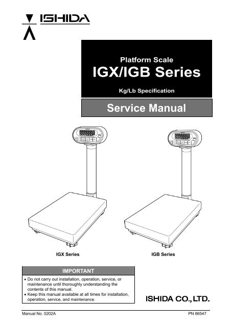
Platform Scale<br />
<strong>IGX</strong>/<strong>IGB</strong> <strong>Series</strong><br />
Kg/Lb Specification<br />
<strong>Service</strong> Manual<br />
<strong>IGX</strong> <strong>Series</strong> <strong>IGB</strong> <strong>Series</strong><br />
IMPORTANT<br />
• Do not carry out installation, operation, service, or<br />
maintenance until thoroughly understanding the<br />
contents of this manual.<br />
• Keep this manual available at all times for installation,<br />
operation, service, and maintenance.<br />
Manual No. 0202A PN 86547
CONTENTS<br />
CHAPTER 1. PRODUCT OVERVIEW ....................................................................................................3<br />
1.1 Machine Outline ...............................................................................................................................3<br />
1.2 Standard Specifications ...................................................................................................................3<br />
1.3 Appearance......................................................................................................................................5<br />
1.4 Display Unit......................................................................................................................................6<br />
1.5 Outer Dimensions ............................................................................................................................7<br />
CHAPTER 2 TEST MODE.......................................................................................................................9<br />
2.1 Operation .........................................................................................................................................9<br />
2.1.1 Starting Each Mode ..................................................................................................................9<br />
2.1.2 Ending Test Mode.....................................................................................................................9<br />
2.1.3 Test Mode Flow.......................................................................................................................10<br />
2.1.4 Key Functions .........................................................................................................................10<br />
2.1.5 Mode List ................................................................................................................................ 11<br />
2.2 C1 Mode (Country No., Scale No., Zero point, Span adjustment) ................................................12<br />
2.2.1 Country No. Table...................................................................................................................12<br />
2.2.2 Scale No. Table.......................................................................................................................13<br />
2.2.3 Operation Procedure ..............................................................................................................14<br />
2.3 C2 Mode: Key Check.....................................................................................................................18<br />
2.4 C3 Mode: Display Check 1 (Simplified Check)..............................................................................18<br />
2.5 C4 Mode: Display Check 2 (Detailed Check) ................................................................................19<br />
2.6 C5 Mode: Program No Display......................................................................................................19<br />
2.7 C6 Mode: RAM Clear and E2ROM Clear......................................................................................20<br />
2.8 C7 Mode: Weighing Condition Setting...........................................................................................21<br />
2.9 C8 Mode: E2ROM Data Reading ..................................................................................................24<br />
2.10 C9 Mode: Board Inspection (A/D Check, I/F Check).....................................................................26<br />
CHAPTER 3 HARDWARE CONFIGURATION .....................................................................................27<br />
3.1 Mechanical Parts ...........................................................................................................................27<br />
3.1.1 Load Cell.................................................................................................................................30<br />
3.2 Electric Parts (<strong>IGB</strong> <strong>Series</strong>).............................................................................................................31<br />
3.2.1 <strong>IGB</strong> Block Diagram .................................................................................................................31<br />
3.2.2 Main Board (PS-018)..............................................................................................................32<br />
3.2.3 Power Board (PS-019) ...........................................................................................................33<br />
3.3 Electric Parts (<strong>IGX</strong> <strong>Series</strong>).............................................................................................................34<br />
3.3.1 <strong>IGX</strong> Block Diagram .................................................................................................................34<br />
3.3.2 Main Board (PS-016)..............................................................................................................35<br />
CHAPTER 4 MAINTENANCE ...............................................................................................................37<br />
4.1 Disassembly Procedure for Display Unit .......................................................................................37<br />
4.2 Replacement of Main Board ..........................................................................................................38<br />
4.2.1 <strong>IGB</strong> <strong>Series</strong> ..............................................................................................................................38<br />
4.2.2 <strong>IGX</strong> <strong>Series</strong> ..............................................................................................................................39<br />
4.3 Replacing and Adjusting Load Cell................................................................................................41<br />
4.3.1 Checking and Adjusting Gap of Four-corner Limit .................................................................42<br />
4.3.2 Performing Zero Point and Span Adjustments .......................................................................43<br />
4.4 Troubleshooting .............................................................................................................................44<br />
Manual No. 085-3435-07 1/45 <strong>IGB</strong>/<strong>IGX</strong> <strong>Series</strong> (Overseas Specifications) <strong>Service</strong> Manual
OUTLINE<br />
• Purpose of this manual<br />
• This manual is to be used as a reference for the maintenance servicing of <strong>IGB</strong> or <strong>IGX</strong> series.<br />
• Related manual<br />
• For placing the product, mounting the display pole, setup mode and setup values, refer to the<br />
operation manual.<br />
• Symbols in the description<br />
1. Warning symbols<br />
Symbol Meaning<br />
Danger<br />
Warning<br />
Caution<br />
2. Explanatory symbols<br />
Reference<br />
Information<br />
Indicates information that, if not heeded, is likely to result in loss of life or serious<br />
injury.<br />
Indicates information that, if not heeded, may result in loss of life or serious<br />
injury.<br />
Indicates information that, if not heeded, could result in relatively serious injury,<br />
damage to the machine or faulty operation.<br />
Symbol Meaning<br />
Note<br />
Reference<br />
Information<br />
Indicates additional information of particular importance.<br />
Indicates a page to refer to.<br />
Indicates information to help you understand the related text.<br />
• Readers of this manual<br />
This manual is designated for use by servicing personnel. Use by other personnel is not permitted.<br />
• This manual may be revised in accordance with modifications to the machine.<br />
• All rights are reserved. Copying any part of this manual is prohibited without the permission of Ishida.<br />
Manual No. 085-3435-07 2/45 <strong>IGB</strong>/<strong>IGX</strong> <strong>Series</strong> (Overseas Specifications) <strong>Service</strong> Manual
Chapter 1. Product Overview<br />
1.1 Machine Outline<br />
• The base of software used is the same as that of the <strong>IGB</strong> and <strong>IGX</strong> <strong>Series</strong>. Therefore, the Setup and<br />
Test mode items are same as those of the <strong>IGB</strong> and <strong>IGX</strong> <strong>Series</strong>. The machine functions are available<br />
within these standard specifications.<br />
• A check function of the upper and lower weight limits are standardly provided with the <strong>IGB</strong> and <strong>IGX</strong><br />
<strong>Series</strong>.<br />
• The main board is different from that of the <strong>IGB</strong> and <strong>IGX</strong> <strong>Series</strong>. However, basic operations are same<br />
for these models.<br />
• For the <strong>IGB</strong> <strong>Series</strong>, an LCD is adopted, and either two dry batteries or an AC adapter can be used as a<br />
power source.<br />
• For the <strong>IGX</strong> <strong>Series</strong>, a VFD is adopted, and a wide selection of power sources ranging from 100 VAC to<br />
240 VAC is available.<br />
1.2 Standard Specifications<br />
Model Name<br />
OIML R76 Class III<br />
Item Contents<br />
<strong>IGB</strong> <strong>Series</strong> <strong>IGX</strong> <strong>Series</strong><br />
<strong>IGB</strong>-60 <strong>IGB</strong>-150 <strong>IGX</strong>-60 <strong>IGX</strong>-150<br />
Weighing Capacity 60kg 150kg 60kg 150kg<br />
Graduation 0.02kg 0.05kg 0.02kg 0.05kg<br />
Accuracy 1/3000<br />
Non-OIML (ASIA)<br />
Weighing Capacity 60kg 150kg 60kg 150kg<br />
Graduation 0.01kg 0.02kg 0.01kg 0.02kg<br />
Accuracy 1/6000 1/7500 1/6000 1/7500<br />
lb/kg Switching Specification (USA)<br />
Weighing Capacity 150lb/60kg 300lb/150kg 150lb/60kg 300lb/150kg<br />
Graduation 0.05lb/0.02kg 0.1lb/0.05kg 0.05lb/0.02kg 0.1lb/0.05kg<br />
Accuracy 1/3000<br />
Weighing Platter 550mm (L) x 400mm (W)<br />
Display: ABS resins<br />
Exterior Material Display pole: Aluminum die-cast<br />
Weighing platter: Stainless (SUS304)<br />
Display Angle Adjust Angle adjustable from the horizon (0°) to the front, Knob locking method<br />
Weight 16.0kg (excluding batteries) 16.8kg<br />
Environmental<br />
Condition<br />
Temperature from -5°C to +40°C, Relative humidity 80%RH (max.) without condensation<br />
Manual No. 085-3435-07 3/45 <strong>IGB</strong>/<strong>IGX</strong> <strong>Series</strong> (Overseas Specifications) <strong>Service</strong> Manual
Model Name<br />
Item Contents<br />
<strong>IGB</strong> <strong>Series</strong> <strong>IGX</strong> <strong>Series</strong><br />
<strong>IGB</strong>-60 <strong>IGB</strong>-150 <strong>IGX</strong>-60 <strong>IGX</strong>-150<br />
Power Source Two dry batteries (not included with the<br />
machine), or optional AC adapter<br />
[Battery Life]<br />
Conditions: No option, Temperature 20°C,<br />
Relative humidity 60%RH<br />
Two “D” size alkaline batteries (Approx. 500H<br />
continuous use)<br />
Power Consumption 25mA 100VAC: 57mA<br />
120VAC: 46mA<br />
220VAC: 28mA<br />
240VAC: 23mA<br />
Display LCD<br />
Numerics: 6 digits, Height 25mm<br />
Mark: Battery. Zero point, Now subtracting<br />
tare, Stable, Weight unit (kg・lb), Over,<br />
Under, Accept<br />
Tare Subtraction Key-in tare<br />
Preset tare<br />
The required transformer is provided for<br />
each 100VAC, 120VAC, 220VAC, or<br />
240VAC.<br />
VFD<br />
Numerics: 5 + 1/2 digits, Height 29mm<br />
Mark: Zero point, Now subtracting tare<br />
LED<br />
Over, Under, Accept<br />
Preset Function [Program Mode] 10 PLUs from PLU 1 to PLU 10 (Tare weight, Upper limit, Lower limit)<br />
Upper Limit Range More than the lower limit, within 5 digits (99999)<br />
Lower Limit Range Less than the upper limit, (5 digits in case of the upper limit = 0)<br />
Auto Power Off [Setup Mode] None/10min./ 20min./ 30min./<br />
40min./ 50min./ 60min.<br />
No<br />
Auto Preset Call-up [Setup Mode] Function “Yes”/”No” selection (PLU 1 is called up when the power is ON.)<br />
Battery Check Mode Yes No<br />
Buzzer No [Setup Mode]<br />
ON/OFF Switch No [Setup Mode]<br />
Option AC adapter (Dealer option)<br />
Manual No. 085-3435-07 4/45 <strong>IGB</strong>/<strong>IGX</strong> <strong>Series</strong> (Overseas Specifications) <strong>Service</strong> Manual
1.3 Appearance<br />
<strong>IGB</strong> <strong>Series</strong> (Asia/Oceania Specification)<br />
<strong>IGX</strong> <strong>Series</strong> (Asia/Oceania Specification)<br />
Manual No. 085-3435-07 5/45 <strong>IGB</strong>/<strong>IGX</strong> <strong>Series</strong> (Overseas Specifications) <strong>Service</strong> Manual
1.4 Display Unit<br />
<strong>IGB</strong> <strong>Series</strong> (Asia/Oceania Specification)<br />
<strong>IGX</strong> <strong>Series</strong> (Asia/Oceania Specification)<br />
Manual No. 085-3435-07 6/45 <strong>IGB</strong>/<strong>IGX</strong> <strong>Series</strong> (Overseas Specifications) <strong>Service</strong> Manual
1.5 Outer Dimensions<br />
(Unit: mm)<br />
Manual No. 085-3435-07 7/45 <strong>IGB</strong>/<strong>IGX</strong> <strong>Series</strong> (Overseas Specifications) <strong>Service</strong> Manual
memo<br />
Manual No. 085-3435-07 8/45 <strong>IGB</strong>/<strong>IGX</strong> <strong>Series</strong> (Overseas Specifications) <strong>Service</strong> Manual
Chapter 2 Test Mode<br />
The Test Mode is used to check the machine when maintenance is performed or to perform settings.<br />
2.1 Operation<br />
The keys used in the following diagram are for Asia/Oceania specifications. For specifications for other<br />
countries, use the corresponding keys.<br />
2.1.1 Starting Each Mode<br />
Scale ON<br />
Release<br />
ON/OFF key,<br />
Then press one<br />
of these keys<br />
while all<br />
segments are<br />
illuminated<br />
2.1.2 Ending Test Mode<br />
C1 Mode<br />
C2 Mode<br />
C3 to C9<br />
Mode<br />
In Mode<br />
In Mode<br />
Start<br />
Check<br />
Press for 2 seconds or more<br />
You cannot return to Cx mode.<br />
C3 to C9<br />
Mode<br />
Operation Manual<br />
Normal Mode<br />
Voltage Check<br />
(<strong>IGB</strong> only)<br />
Setup Mode<br />
Program Mode<br />
Test Mode<br />
Scale OFF<br />
Manual No. 085-3435-07 9/45 <strong>IGB</strong>/<strong>IGX</strong> <strong>Series</strong> (Overseas Specifications) <strong>Service</strong> Manual
2.1.3 Test Mode Flow<br />
2.1.4 Key Functions<br />
C1<br />
C2<br />
C3 to C6<br />
C7<br />
C8, C9<br />
Key Function<br />
Memory<br />
switch<br />
Turns the power ON or OFF for the <strong>IGB</strong> <strong>Series</strong>.<br />
Turns the power ON or OFF for the <strong>IGX</strong> <strong>Series</strong>.<br />
+5V is always supplied to the circuit voltage.<br />
Increases the numeric value (when the numeric value is set).<br />
Advances the mode (when conditions are set).<br />
Adjusts the zero point.<br />
Decreases the numeric value (when the numeric value is set).<br />
Reverses the mode (when conditions are set).<br />
Adjusts the span point.<br />
Determines the data in the Details Mode.<br />
To each C1<br />
mode setup<br />
Key check<br />
mode<br />
Each mode<br />
operation<br />
Scale function<br />
Setup mode<br />
Each mode<br />
operation<br />
Changes between “+ Adjust” (ZERO key [u display]) and “- Adjust” (TARE key<br />
[d display]) when the span is adjusted.<br />
Returns to each mode.<br />
(Tact switch on the main board)<br />
Saves the E2ROM data of each item setting of C1 mode.<br />
Manual No. 085-3435-07 10/45 <strong>IGB</strong>/<strong>IGX</strong> <strong>Series</strong> (Overseas Specifications) <strong>Service</strong> Manual
2.1.5 Mode List<br />
Mode Contents<br />
*C1 Country No., Scale No., Zero point, Span adjustment<br />
C2 Key check<br />
C3 Display check 1 (simplified check), All LEDs light up<br />
C4<br />
Display check 2 (detailed check), Each segment lights in sequence for each display<br />
digit.<br />
C5 Program No. display<br />
*C6<br />
RAM clear (Program mode data)<br />
E2ROM clear (Program mode data and Test mode C1 data)<br />
(Span adjustment is required)<br />
*C7 Settings for weighing conditions<br />
C8 Reading E2ROM data<br />
C9 Board check (A/D check, Interface check) for factory inspection<br />
Manual No. 085-3435-07 11/45 <strong>IGB</strong>/<strong>IGX</strong> <strong>Series</strong> (Overseas Specifications) <strong>Service</strong> Manual
2.2 C1 Mode (Country No., Scale No., Zero point, Span adjustment)<br />
2.2.1 Country No. Table<br />
Country Name USA 1 EU AUS ASIA USA 2 JPN<br />
Country Code 0 1 2 3 4 5 6 7 8 9 10 99<br />
ADRS POS WGT Function Default Data (Change not allowed)<br />
112 A H Start width 2 2 2 2 2 2 2 2 2 2 4 -<br />
B H Stable/Re-stable count 3 3 3 3 3 3 3 3 3 3 3 -<br />
113 A H Stable/Re-stable width 4 4 4 4 4 4 4 4 4 4 4 -<br />
B H Re-stable operation start width<br />
114 A 1 Zero point mark<br />
2 Over-scale display<br />
4 Display less than true zero<br />
8 Decimal point display<br />
B 1 Over-scale range<br />
2 Tare subtraction<br />
4 Tare clear with ZERO key<br />
8 Zero suppress<br />
115 A 1 Key-in tare subtraction<br />
Reference<br />
2 Zero tracking<br />
4 Micro weight follow-up<br />
8 Unstable width<br />
B 1 PLU display (<strong>IGB</strong> only)<br />
Note<br />
Reference<br />
2 Stable display (IWB only)<br />
4 Reserved<br />
8 Reserved<br />
4 4 4 4 4 4 4 4 4 4 4 -<br />
2 8 0 8 2 8 0 8 4 0 5 -<br />
0 6 6 0 0 6 6 0 0 6 0 -<br />
0 0 0 0 0 0 0 0 0 0 4 -<br />
0 6 6 6 4 6 6 6 5 5 5 -<br />
Manual No. 085-3435-07 12/45 <strong>IGB</strong>/<strong>IGX</strong> <strong>Series</strong> (Overseas Specifications) <strong>Service</strong> Manual<br />
IDV<br />
SET<br />
1. By setting the country code, weighing conditions will function based on the default data from<br />
address 112 to 115.<br />
2. The data is set to meet certified conditions for each country, so there is no need to change the<br />
data.<br />
3. Position “A” indicates the upper position of one-byte data, and “B” indicates the lower position.<br />
4. As for Weight, a function is selected with “1”, “2”, “4”, and “8” in bit unit, and “H” indicates<br />
Hexadecimal data.<br />
5. Individual setting value “99” cannot be entered. (Displayed only when settings are changed in C7<br />
mode)<br />
6. “USA 2” code is settings to allow changing between “lb” and “kg” at anytime even in cases other<br />
than a stable condition at zero point. (“USA 1” can change between “lb” and “kg” only when the<br />
condition is stabilized at zero point)<br />
When using this function, a maximum of 0.2e error may occur in weighing immediately after the<br />
change. This error is calibrated by zero point adjustment (or zero tracking), and an accurate<br />
weighing is guaranteed.<br />
When selecting the weighing capacity exclusively for either “lb” or “kg”, use “USA 1”.<br />
Refer to “Weighing Condition Data Table” for detailed function selection.
2.2.2 Scale No. Table<br />
Scale No. Specifications<br />
Reference<br />
Address<br />
110A 110B 111A 111B<br />
Default Data<br />
0 150kg (0.05kg/0.02kg) Multi Interval 6 C 3 8<br />
1 60kg (0.02kg/0.01kg) Multi Interval 2 B 3 8<br />
2 30kg (0.01kg/0.005kg) Multi Interval B B 3 8<br />
3 15kg (0.005kg/0.002kg) Multi Interval 7 C 3 8<br />
4 6kg (0.002kg/0.001kg) Multi Interval 3 B 3 8<br />
5 6000g (2g/1g) Multi Interval 0 B B 8<br />
6 3000g (1g/0.5g) Multi Interval 9 B B 8<br />
7 150kg (0.02kg) 1/7500 Single Range 6 B 2 8<br />
8 60kg (0.01kg) 1/6000 Single Range 2 B 2 8<br />
9 30kg (0.005kg) 1/6000 Single Range B B 2 8<br />
10 15kg (0.002kg) 1/7500 Single Range 7 B 2 8<br />
11 6kg (0.001kg) 1/6000 Single Range 3 B 2 8<br />
12 300kg (0.1kg) 1/3000 Single Range 1 B 2 8<br />
13 150kg (0.05kg) 1/3000 Single Range A 8 2 8<br />
14 60kg (0.02kg) 1/3000 Single Range 6 8 2 8<br />
15 30kg (0.01kg) 1/3000 Single Range 2 8 2 8<br />
16 15kg (0.005kg) 1/3000 Single Range B 8 2 8<br />
17 6kg (0.002kg) 1/3000 Single Range 7 8 2 8<br />
18 6000g (2g) 1/3000 Single Range 4 8 A 8<br />
19 3000g (1g) 1/3000 Single Range 0 8 A 8<br />
20 150kg/60kg (0.05kg/0.02kg) Dual Range 6 C 5 8<br />
21 60kg/30kg (0.02kg/0.01kg) Dual Range 2 B 5 8<br />
22 30kg/15kg (0.01kg/0.005kg) Dual Range B B 5 8<br />
23 15kg/6kg (0.005kg/0.002kg) Dual Range 7 C 5 8<br />
24 6kg/3kg (0.002kg/0.001kg) Dual Range 3 B 5 8<br />
25 6000g/3000 (2g/1g) Dual Range 0 B D 8<br />
26 3000g/1500 (1g/0.5g) Dual Range 9 B D 8<br />
27 150kg/150k (0.1kg/0.05kg Dual Range<br />
Fishery specification<br />
28 150kg (0.05kg) 1/3000 Single Range<br />
Body weight specification<br />
29 30kg (0.01kg) 1/3000 Single Range<br />
Baby scale specification<br />
A 8 5 8<br />
A 8 4 2<br />
2 8 4 2<br />
30 300lb/150kg (1/3000) Multi Interval 6 C 7 8<br />
31 150lb/60kg (1/3000) Multi Interval 2 B 7 8<br />
32 60lb/30kg (1/3000) Multi Interval B B 7 8<br />
33 30lb/15kg (1/3000) Multi Interval 7 C 7 8<br />
34 15lb/6kg (1/3000) Multi Interval 3 B 7 8<br />
99 Individual scale settings - - - -<br />
Note<br />
Reference<br />
1. By setting the Scale No., the scale will function according to default data of addresses 110 and<br />
111.<br />
2 The above data determines each specification, so changing the data is prohibited.<br />
3 Data A indicates the upper position of the one-byte data, and B indicates the lower position.<br />
Refer to “Weighing Condition Data Table” for data details.<br />
Manual No. 085-3435-07 13/45 <strong>IGB</strong>/<strong>IGX</strong> <strong>Series</strong> (Overseas Specifications) <strong>Service</strong> Manual
2.2.3 Operation Procedure<br />
Operation Display<br />
1. Starting Test Mode (C1)<br />
Press ON/OFF.<br />
Press and hold ZERO(+) while all segments are lit.<br />
Press SET.<br />
2. Setting Country Number<br />
To increase the number, press ZERO(+).<br />
To decrease the number, press TARE(-).<br />
Press SET.<br />
[Example] Asia = 3<br />
3. Setting Scale Number<br />
When setting “60kg”, select “08”.<br />
Press SET.<br />
4. Selecting Weight at Span Adjustment<br />
The following weight can be selected:<br />
kg: 1/1.0→1/2.0→1/2.5→1/5.0 of weighing capacity<br />
lb: 1/1.0→1/2.0→1/2.5→1/5.0 of weighing capacity<br />
Pressing ZERO(+) selects the next item in the above<br />
・<br />
sequence, and pressing TARE(-) selects the previous item.<br />
[Example] Selecting “kg” unit and “1/2.0” for weighing<br />
capacity “150kg” will require the total 75kg<br />
weight.<br />
To change between “lb” and “kg”, press ZERO(+) and<br />
TARE(-) at the same time.<br />
5. Zero Point Adjustment<br />
After selecting the weight amount, ensure that nothing is<br />
placed on the weighing platter, then press SET.<br />
The previously set zero point A/D data will be displayed.<br />
Zero point indicator will light up.<br />
Press ZERO(+) to set “20000” counts forcibly.<br />
Zero point indicator will go off.<br />
kg unit: Same weight is used as weighing<br />
capacity.<br />
kg unit: Half weight is used of weighing<br />
capacity.<br />
lb unit: Same weight is used as weighing<br />
capacity.<br />
Manual No. 085-3435-07 14/45 <strong>IGB</strong>/<strong>IGX</strong> <strong>Series</strong> (Overseas Specifications) <strong>Service</strong> Manual
Operation Display<br />
6. Span Adjustment<br />
Place the selected weight on the weighing platter, then press<br />
TARE(-).<br />
[Example] 60kg Scale: Weight selection: “kg” unit and “1/1”<br />
Place a 60kg weight, 30000 + Zero point 20000 =<br />
50000 counts<br />
In case of “kg” unit “1/2” for a weight selection, place<br />
a 30kg weight, then 15000 + Zero point 20000 =<br />
35000 counts<br />
One graduation equals 5 counts.<br />
・<br />
Processing is automatically executed in the following order:<br />
[Calib] (Calibration) Computing process executing<br />
[C- OK] (Calibration OK) Computing result succeeded<br />
[No. of adjusted counts] Computing result<br />
[C-Err] will be displayed, indicating a computing result error<br />
when span adjustment is performed without placing a weight.<br />
Place a weight and press TARE(-).<br />
7. Saving Data<br />
To save Country No., Scale No., Zero point, and Span data in<br />
E2ROM.<br />
Remove the weight from the weighing platter.<br />
・<br />
Remove the seal covering the opening on the rear<br />
・<br />
case of display unit.<br />
・ Insert a thin rod such as the inner shaft of a<br />
ball-point pen into the hole, and push the Memory Switch<br />
located on the main board.<br />
When writing has finished normally, [S-OK] will be<br />
displayed.<br />
To release the above status, press COLUMN.<br />
・<br />
Then, the display will return to A/D data.<br />
8. Finishing Procedure<br />
・ Press ON/OFF to finish this procedure.<br />
Manual No. 085-3435-07 15/45 <strong>IGB</strong>/<strong>IGX</strong> <strong>Series</strong> (Overseas Specifications) <strong>Service</strong> Manual<br />
<br />
<br />
(Calibration error)<br />
OFF status
When Performing Fine Span Adjustment<br />
1. Trimming<br />
After span adjustment, press COLUMN while the A/D data<br />
is displayed.<br />
[Tri-] (Trimming) display will appear.<br />
(This is possible even with the weight placed)<br />
2. Trimming Up<br />
Press ZERO(+), then [Tri-U] will be displayed.<br />
Press ZERO(+) for the desired number of times to increase<br />
the span.<br />
3. Trimming Down<br />
Press TARE(-), then [Tri-d] will be displayed.<br />
Press TARE(-) for the desired number of times to decrease<br />
the span.<br />
Note<br />
The change amount for one time may differ<br />
depending on each machine; however,<br />
approximately one count for one time is average.<br />
4. Repeating Steps<br />
Press COLUMN, then A/D data will be displayed.<br />
Place a weight on the weighing platter, and perform<br />
adjustment by repeating steps 1, 2, and 3 above.<br />
5. Saving Data<br />
After completing the adjustment, press COLUMN to save<br />
the data.<br />
Manual No. 085-3435-07 16/45 <strong>IGB</strong>/<strong>IGX</strong> <strong>Series</strong> (Overseas Specifications) <strong>Service</strong> Manual
Memory Switch<br />
The memory switch is located on the main board.<br />
<strong>IGB</strong> <strong>Series</strong><br />
Memory switch Memory switch<br />
Pushing memory switch<br />
<strong>IGX</strong> <strong>Series</strong><br />
Manual No. 085-3435-07 17/45 <strong>IGB</strong>/<strong>IGX</strong> <strong>Series</strong> (Overseas Specifications) <strong>Service</strong> Manual
2.3 C2 Mode: Key Check<br />
Operation Display<br />
1. Starting Test Mode (C1)<br />
Press ON/OFF.<br />
Press and hold ZERO(+) while all segments are lit.<br />
2. Entering C2 Mode<br />
Press ZERO(+).<br />
3. Checking Keys<br />
Press SET.<br />
[KEY-0] indicates that there is no key entry.<br />
4. Checking Keys<br />
ZERO(+) 1 TARE(-) 2 ∗ 3<br />
SET 4 EXT. INPUT 5 MEMORY SW 6<br />
5. Finishing Procedure<br />
Press ON/OFF to finish this procedure.<br />
2.4 C3 Mode: Display Check 1 (Simplified Check)<br />
OFF status<br />
Operation Display<br />
1. Starting Test Mode (C1)<br />
Press ON/OFF.<br />
Press and hold ZERO(+) while all segments are lit.<br />
2. Entering C3 Mode<br />
Press ZERO(+) twice.<br />
3. Checking Displays<br />
Press SET.<br />
The display shows self-diagnostic check.<br />
4. Returning to Test Mode<br />
Press COLUMN to return to Test Mode.<br />
Manual No. 085-3435-07 18/45 <strong>IGB</strong>/<strong>IGX</strong> <strong>Series</strong> (Overseas Specifications) <strong>Service</strong> Manual
2.5 C4 Mode: Display Check 2 (Detailed Check)<br />
Operation Display<br />
1. Starting Test Mode (C1)<br />
Press ON/OFF.<br />
Press and hold ZERO(+) while all segments are lit.<br />
2. Entering C4 Mode<br />
Press ZERO(+) three times.<br />
3. Checking Displays<br />
Press SET.<br />
The display shows self-diagnostic check. <br />
4. Returning to Test Mode<br />
Press COLUMN to return to Test Mode.<br />
2.6 C5 Mode: Program No Display<br />
Operation Display<br />
1. Starting Test Mode<br />
Press ON/OFF.<br />
Press and hold ZERO(+) while all segments are lit.<br />
2. Entering C5 Mode<br />
Press ZERO(+) four times.<br />
3. Displaying Program Number<br />
Press SET.<br />
The installed program number (D005) will be displayed.<br />
4. Returning to Test Mode<br />
Press COLUMN to return to Test Mode.<br />
Manual No. 085-3435-07 19/45 <strong>IGB</strong>/<strong>IGX</strong> <strong>Series</strong> (Overseas Specifications) <strong>Service</strong> Manual
2.7 C6 Mode: RAM Clear and E2ROM Clear<br />
Operation Display<br />
1. Starting Test Mode<br />
Press ON/OFF.<br />
Press and hold ZERO(+) while all segments are lit.<br />
2. Entering C6 Mode<br />
Press ZERO(+) five times.<br />
3. Press SET.<br />
4. RAM Clear<br />
(Preset data of Program Mode is cleared)<br />
Press ZERO(+).<br />
Press ZERO(+).<br />
5. Press COLUMN to return to Test Mode.<br />
E2ROM Clear (Initializing E2ROM data)<br />
6. Press SET.<br />
7. Push the Memory Switch (SW1) located on the main<br />
board.<br />
(This does not work when there has been no data<br />
change)<br />
Note<br />
C1 data and setting data (F01toF17) have been<br />
initialized.<br />
Settings are required.<br />
8. Press ON/OFF.<br />
After initialization, nothing except “C1” will be displayed.<br />
C1 data settings (Country No., Scale No., Zero point,<br />
Span adjustment) are required.<br />
Manual No. 085-3435-07 20/45 <strong>IGB</strong>/<strong>IGX</strong> <strong>Series</strong> (Overseas Specifications) <strong>Service</strong> Manual
2.8 C7 Mode: Weighing Condition Setting<br />
Note<br />
Setting Country No. and Scale No. determine the weighing conditions for securing certified<br />
specifications of the country.<br />
Individual contents can be changed in this mode.<br />
Specifications must be selected when used overseas.<br />
Operation Display<br />
1. Starting Test Mode<br />
Press ON/OFF.<br />
Press and hold ZERO(+) while all segments are lit.<br />
2. Entering C7 Mode<br />
Press ZERO(+) six times.<br />
Or, press TARE(-) three times.<br />
3. Press SET.<br />
To change data:<br />
Select the desired data by pressing ZERO(+) to increase,<br />
or TARE(-) to decrease the address.<br />
To fix the data or advance the address:<br />
Press SET.<br />
4. After changing data<br />
Push the Memory Switch (SW1) located on the main<br />
board.<br />
(This does not work when there was no data change)<br />
5. Press COLUMN twice to return to Test Mode.<br />
Reference<br />
Reference<br />
Addresses for weighing condition settings are from 110 to 115.<br />
Refer to the next page.<br />
3-digit address + A (Upper data) - Data<br />
3-digit address + B (Lower data) - Data<br />
Manual No. 085-3435-07 21/45 <strong>IGB</strong>/<strong>IGX</strong> <strong>Series</strong> (Overseas Specifications) <strong>Service</strong> Manual
Weighing Condition Setting Table<br />
Address Weight Item Data<br />
110A 1 Decimal point position 0: 0 1: 0.0<br />
2 2: 0.00 3: 0.000<br />
4 Minimum graduation 0: 1 (1-2 change in Dual range/ Multi Interval)<br />
4: 2 (2-5-10 change in Dual range/ Multi Interval)<br />
8 8: 5 (5-10-20 change in Dual range/ Multi Interval)<br />
C: Invalid<br />
110B - Accuracy (Resolution) 0: 1/500 1: 1/600 2: 1/750 3: 1/1000<br />
4: 1/1200 5: 1/1500 6: 1/2000 7: 1/2500<br />
8: 1/3000 9: 1/4000 A: 1/5000 B: 1/6000<br />
C: 1/7500 D: 1/10000 E: 1/12000 F: 1/15000<br />
111A<br />
111B<br />
1<br />
2<br />
4<br />
8<br />
1<br />
2<br />
4<br />
8<br />
Changing method 0: Single range LED stable display only (<strong>IGX</strong>)<br />
1: 1/3000 Multi interval Stabe/Upper/Lower display (<strong>IGB</strong>)<br />
2: Single range Upper/Lower display (<strong>IGX</strong>)<br />
3: 1/3000 Multi interval Stabe/Upper/Lower display (<strong>IGB</strong>)<br />
4: Single range (Body weight specification)<br />
5: 1/3000 Dual range (A/B range change)<br />
6: Single range (lb/kg change)<br />
7: 1/3000 Multi interval (lb/kg change)<br />
Weight unit<br />
(Valid only for<br />
communications)<br />
Filter setting<br />
Do not change the data.<br />
<br />
0 + 0: kg (kg - lb)<br />
8 + 0: g<br />
0 + 1: lb<br />
8 + 1: oz<br />
(Cut off) (Notch) (Output rate)<br />
0: 0.66Hz 2.50Hz 400ms<br />
2: 0.84Hz 3.20Hz 312ms<br />
4: 1.05Hz 4.00Hz 250ms<br />
6: 1.31Hz 5.00Hz 200ms<br />
8: 1.68Hz 6.40Hz 156ms<br />
A: 2.10Hz 8.00Hz 125ms<br />
C: 2.62Hz 10.00Hz 100ms<br />
E: 3.35Hz 12.80Hz 78ms<br />
Manual No. 085-3435-07 22/45 <strong>IGB</strong>/<strong>IGX</strong> <strong>Series</strong> (Overseas Specifications) <strong>Service</strong> Manual
Address Weight Item Data<br />
112A - Start width 0: ±1/50 (±2%) of weighing capacity<br />
1: ±1/25 (±4%) of weighing capacity<br />
2: ±1/10 (±10%) of weighing capacity<br />
3: ±1/7.5 (±13.3%) of weighing capacity<br />
4: ±1/6 (±16.6%) of weighing capacity<br />
5: ±1/5 (±20%) of weighing capacity<br />
6: ±1/4 (±25%) of weighing capacity<br />
7: ±1/3 (±33.3%) of weighing capacity<br />
8: ±1/2 (±50%) of weighing capacity<br />
9 and more: Invalid<br />
112B - Stable/Re-stable count 0 through 15 times<br />
113A - Stable/Re-stable width n=0 through 15 (±n/10 e)<br />
113B - Re-stable operation start<br />
width<br />
114A<br />
114B<br />
115A<br />
115B<br />
n=0 through 15 (±n/10 e)<br />
1 Zero point mark 0: Light at true zero 1: Light at dummy zero<br />
2 Over-scale display 0: Blank 1:”OL”<br />
4 Display below true zero 0: “-----------“ 1: Minus numeric value<br />
8 Decimal point form 0: ”.” 1: ”,”<br />
1 Over-scale range 0: Display upto +9e 1: Display upto +3e<br />
2 Tare subtraction 0: Yes 1: No<br />
4 Tare clear with ZERO key 0: No 1: Yes<br />
8 Zero supress display<br />
(Multi Interval<br />
specification only)<br />
1 Key-in preset tare<br />
subtraction and preset<br />
single weight function<br />
Preset unit weight<br />
function<br />
0: Yes 1: No<br />
0: Yes 1: No<br />
2 Zero tracking 0: Yes 1: No<br />
4 Micro weight follow-up 0: Yes 1: No<br />
8 Unstable width 0: ±0.5e 1: ±20e<br />
1 No. of PLUs and PLU<br />
display (<strong>IGB</strong> only)<br />
2 Stable display<br />
(<strong>IGB</strong> only)<br />
0: 10 PLUs 1: 5 PLUs<br />
Display No display<br />
0: “∗” display 1: “▼” cursor display<br />
4 Weight unit cursor display 0: Always light 1: Light only when “No change”is set<br />
8 Reserved<br />
Manual No. 085-3435-07 23/45 <strong>IGB</strong>/<strong>IGX</strong> <strong>Series</strong> (Overseas Specifications) <strong>Service</strong> Manual
2.9 C8 Mode: E2ROM Data Reading<br />
Data from address 000 to address 127 can be read.<br />
Operation Display<br />
1. Starting Test Mode<br />
Press ON/OFF.<br />
Press and hold ZERO(+) while all segments are lit.<br />
2. Entering C8 Mode<br />
Press ZERO(+) seven times.<br />
Or, press TARE(-) twice.<br />
3. Press SET.<br />
To change an address<br />
Press ZERO(+) to increase an address.<br />
Press TARE(-) to decrease an address.<br />
Address 000<br />
Address 110<br />
Address 127<br />
TARE key<br />
C8 Starting address<br />
ZERO key<br />
4. Press COLUMN to return to Test Mode.<br />
E2ROM Data<br />
Address 3 digits -Data 1 byte<br />
Address Item Data Range Remarks<br />
0 to 99 Preset data (10 PLUs)<br />
Upper limit 17bit<br />
Lower limit 17bit<br />
Tare amount (A range) 18bit<br />
Tare amount (B range)/Single weight 20bit<br />
Check sum 8bit<br />
100A Scale mode data Capacity (bit1)<br />
lb mode (bit2)<br />
Counting (bit3)<br />
100B Reserved -<br />
0 to 60000<br />
0 to F<br />
Data set in Program<br />
Mode of Operation<br />
Manual.<br />
10 byte × 10 data<br />
Reference<br />
Reference<br />
Refer to <strong>IGB</strong>/<strong>IGX</strong><br />
Operation Manual.<br />
Manual No. 085-3435-07 24/45 <strong>IGB</strong>/<strong>IGX</strong> <strong>Series</strong> (Overseas Specifications) <strong>Service</strong> Manual
Address Item Data Range Remarks<br />
101 100A and 100B check data<br />
(Writing twice)<br />
102A Selection of ON/OFF key function (bit 0)<br />
Selection of Preset auto call-up function (bit 1)<br />
Selection of 16/24 digit printer (bit 2)<br />
Selection of Date print function (bit 3)<br />
102B Selection of Preset No. print function (bit4)<br />
Selection of single/consecutive chit print (bit5)<br />
Selection of Tare amount print function (bit6)<br />
Selection of Upper/Lower limits print function (bit7)<br />
Manual No. 085-3435-07 25/45 <strong>IGB</strong>/<strong>IGX</strong> <strong>Series</strong> (Overseas Specifications) <strong>Service</strong> Manual<br />
-<br />
0 to 1 (F1)<br />
0 to 1 (F2)<br />
0 to 1 (F3)<br />
0 to 1 (F4)<br />
0 to 1 (F5)<br />
0 to 1 (F6)<br />
0 to 1 (F7)<br />
0 to 1 (F8)<br />
103A Baud rate setting (bit 0 to 3) 0 to F (F9)<br />
103B Output message specification (bit 4 to 7) 0 to F (F10)<br />
104A Data output method (bit 0 to 3) 0 to F (F11)<br />
104B Data output condition (bit 4 to 7) 0 to F (F12)<br />
105A Contact output signal setting (bit 0 to 3) 0 to F (F13)<br />
105B Contact input signal setting (bit 4 to 7) 0 to F (F14)<br />
106A High-level buzzer output setting (bit 0 to 3) 0 to F (F15)<br />
106B Built-in buzzer selection function (bit 4 to 7) 0 to F (F16)<br />
107A Automatic power off setting (bit 0 to 3) 0 to 6 (F17)<br />
107B Reserved<br />
108 to 109 Check sum from 102 to 107 -<br />
Data set in Setup<br />
Mode of Operation<br />
Manual.<br />
Reference<br />
Reference<br />
Refer to <strong>IGB</strong>/<strong>IGX</strong><br />
Operation Manual.<br />
110 to 115 Weighing condition setting data Refer to Weighing<br />
condition setting table.<br />
116A Country code (Refer to Country code table) 0 to F (Default 10: Japan)<br />
116B Reserved 0<br />
117A Reserved 0<br />
117B Reserved 0<br />
118 to 120 A/D zero point data (adref) 24 bit<br />
121 to 123 A/D calibration data (adwidth) 24 bit<br />
124<br />
Weighing capacity setting (Refer to Capacity setting<br />
table)<br />
125A JAPAN only 0 to F<br />
125B Span adjusted flag 5H or others<br />
126, 127 Check sum from 100 to 113. -<br />
00 to 99 (Default 1: 60kg)<br />
5H=OK<br />
Others=Error
2.10 C9 Mode: Board Inspection (A/D Check, I/F Check)<br />
This mode is for factory inspection, and shall not be used for maintenance.<br />
1. Starting Test Mode<br />
Press ON/OFF.<br />
Press and hold ZERO(+) while all segments are lit.<br />
2. Entering C9 Mode<br />
Press ZERO(+) eight times.<br />
Or, press TARE(-).<br />
3. Press SET.<br />
Span adjusted A/D data is displayed.<br />
Operation Display<br />
4. Press SET.<br />
A/D converter output value is displayed.<br />
However, the lower 3 bits of 24-bit output change rapidly and<br />
are outside of visual inspection range, so they are excluded.<br />
5. Press ZERO(+).<br />
Used for A/D board drift inspection.<br />
The inspection result is displayed: OK or Err<br />
6. Press TARE(-).<br />
Connect the inspection jig and all I/O ports are checked.<br />
The inspection result is displayed: OK or Err<br />
7. Press COLUMN to return to Key Test Mode.<br />
Manual No. 085-3435-07 26/45 <strong>IGB</strong>/<strong>IGX</strong> <strong>Series</strong> (Overseas Specifications) <strong>Service</strong> Manual
Chapter 3 Hardware Configuration<br />
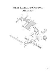
3.1 Mechanical Parts<br />
Manual No. 085-3435-07 27/45 <strong>IGB</strong>/<strong>IGX</strong> <strong>Series</strong> (Overseas Specifications) <strong>Service</strong> Manual
<strong>IGB</strong> <strong>Series</strong> <strong>Service</strong> Parts List<br />
No. Part Name Remark Part No. Q'ty<br />
1 CASE FRONT 900-0756-05 1<br />
2 CASE REAR ’BATTERY’ 900-0753-04 1<br />
3 COVER ’BATTERY’ 900-0754-08 1<br />
6 BRACKET 900-0725-00 1<br />
7 BRACKET ’DISPLAY’ 900-0726-03 1<br />
10 WASHER ’RUBBER’ 900-0748-05 2<br />
11 FILTER ’DISPLAY’ 900-0755-01 1<br />
12 SHEET ’DISPLAY’ 60kg Varied per country 1<br />
12 SHEET ’DISPLAY’ 150kg Varied per country 1<br />
14 SHEET ’COVER’ 900-0793-03 1<br />
15 SPRING 1 900-1013-05 1<br />
16 SPRING 2 900-1014-18 1<br />
17 CUSHION BATTERY 900-0319-01 4<br />
18 NAME PLATE ’SPEC.’ 60kg Varied per country 1<br />
18 NAME PLATE ’SPEC.’ 150kg Varied per country 1<br />
19 PWB PS-018 900-0677-04 1<br />
20 PWB PS-019 900-0767-06 1<br />
22 CABLE LOCKING (PG-11) 900-0758-02 1<br />
23 HARNESS 'S2' GND 900-0772-05 1<br />
25 SCREW M 4×45 900-0842-02 2<br />
26 SHEET 900-1064-05 2<br />
31 SIDE COVER 900-0037-11 1<br />
32 POLE STAND 900-0032-49 1<br />
33 RUBBER RING 900-0207-07 1<br />
34 PLATTER 072-8847-05 1<br />
35 SHEET ’PLATTER ’ 900-0100-02 1<br />
36 PLATE SUPPORT 900-0021-11 1<br />
37 BASE 900-0020-35 1<br />
38 FOOT ’LEVEL’ 900-0022-05 4<br />
39 PLATE A ’LEVEL’ 900-0222-03 1<br />
40 LEVEL UNIT ASS. 900-0315-15 1<br />
41 BRACKET ’LEVEL’ 900-0010-01 1<br />
42 LOAD CELL (LOC-ISS10-100kg) 60kg 900-0815-01 1<br />
42 LOAD CELL (LOC-ISS10-300kg) 150kg 900-0816-05 1<br />
Note: Part numbers may change without notice due to product improvements.<br />
Manual No. 085-3435-07 28/45 <strong>IGB</strong>/<strong>IGX</strong> <strong>Series</strong> (Overseas Specifications) <strong>Service</strong> Manual
<strong>IGX</strong> <strong>Series</strong> <strong>Service</strong> Parts List<br />
No. Part Name Remark Part No. Q'ty<br />
1 CASE FRONT 900-0756-05 1<br />
2 CASE REAR ’TRANSFORMER’ 900-0757-09 1<br />
3 COVER ’BATTERY’ 900-0754-08 1<br />
6 BRACKET 900-0725-00 1<br />
7 BRACKET ’DISPLAY’ 900-0726-03 1<br />
8 PLATE EARTH 900-0727-07 1<br />
9 BRACKET 'CASE' 900-0829-03 1<br />
10 WASHER ’RUBBER ’ 900-0748-05 2<br />
11 FILTER ’DISPLAY’ 900-0755-01 1<br />
12 SHEET ’DISPLAY’ 60kg Varied per country 1<br />
12 SHEET ’DISPLAY’ 150kg Varied per country 1<br />
13 SHEET ’AC ADAPTER’ 900-0770-08 1<br />
18 NAME PLATE ’SPEC ’ 60kg Varied per country 1<br />
18 NAME PLATE ’SPEC.’ 150kg Varied per country 1<br />
19 PWB PS-016 900-0676-01 1<br />
21 TRANSFORMER ASSY 900-1697-02 1<br />
22 CABLE LOCKING (PG-11) 900-0758-02 2<br />
23 HARNESS 'S2' GND 900-0772-05 1<br />
24 HARNESS 'C3' POWER CORD Varied per country 1<br />
26 SHEET 900-1064-05 2<br />
31 SIDE COVER 900-0037-11 1<br />
32 POLE STAND 900-0032-49 1<br />
33 RUBBER RING 900-0207-07 1<br />
34 PLATTER 072-8847-05 1<br />
35 SHEET ’PLATTER ’ 900-0100-02 1<br />
36 PLATE SUPPORT 900-0021-11 1<br />
37 BASE 900-0020-35 1<br />
38 FOOT ’LEVEL ’ 900-0022-05 4<br />
39 PLATE A ’LEVEL ’ 900-0222-03 1<br />
40 LEVEL UNIT ASS. 900-0315-15 1<br />
41 BRACKET ’LEVEL ’ 900-0010-01 1<br />
42 LOAD CELL (LOC-ISS10-100kg) 60kg 900-0815-01 1<br />
42 LOAD CELL (LOC-ISS10-300kg) 150kg 900-0816-05 1<br />
Note: Part numbers may change without notice due to product improvements.<br />
Manual No. 085-3435-07 29/45 <strong>IGB</strong>/<strong>IGX</strong> <strong>Series</strong> (Overseas Specifications) <strong>Service</strong> Manual
3.1.1 Load Cell<br />
Load cell<br />
Top of base<br />
Bottom of base<br />
Manual No. 085-3435-07 30/45 <strong>IGB</strong>/<strong>IGX</strong> <strong>Series</strong> (Overseas Specifications) <strong>Service</strong> Manual
3.2 Electric Parts (<strong>IGB</strong> <strong>Series</strong>)<br />
3.2.1 <strong>IGB</strong> Block Diagram<br />
Display Unit<br />
Main Board (PS-018)<br />
Front Case<br />
Rear Case<br />
Power Board<br />
(PS-019)<br />
AC Adaptor<br />
JACK<br />
AC Adaptor<br />
Scale Unit<br />
Load Cell<br />
XH 2p<br />
XH 2p<br />
Ferrite Core<br />
Manual No. 085-3435-07 31/45 <strong>IGB</strong>/<strong>IGX</strong> <strong>Series</strong> (Overseas Specifications) <strong>Service</strong> Manual<br />
MK 2p<br />
Battery<br />
Battery
3.2.2 Main Board (PS-018)<br />
Parts Surface of Main Board (The LCD and tact keys are installed on the soldering surface)<br />
(1) SW1: Memory Switch<br />
Used to write the data when performing initialization in Test Mode.<br />
Used to save (write) the data in E2ROM after changing Country No. and Scale No., and performing<br />
Span Adjustment.<br />
(2) Connector XJ1<br />
This connector is not used.<br />
Pin No. Signal Name Pin No. Signal Name<br />
1 IN1 6 NC<br />
2 OUT4 7 RESET<br />
3 OUT3 8 VPP<br />
4 OUT2 9 GND<br />
5 OUT1<br />
10 VCC<br />
(3) Connector XJ2<br />
This connector is used for DC input.<br />
Pin No. Signal Name<br />
1 +DC<br />
2 -DC<br />
Manual No. 085-3435-07 32/45 <strong>IGB</strong>/<strong>IGX</strong> <strong>Series</strong> (Overseas Specifications) <strong>Service</strong> Manual
(4) Connector XJ3<br />
This connector is not used.<br />
Pin No. Signal Name<br />
1 Buzzer<br />
2 DTR<br />
3 RxD<br />
4 TxD<br />
5 GND<br />
6 FG<br />
(5) Program Memory Media<br />
Mask ROM 256KB (Writing or replacement is not possible)<br />
There is no compatibility between the <strong>IGB</strong> <strong>Series</strong> main board (PS-018) and the <strong>IGX</strong> <strong>Series</strong><br />
main board (PS-016); However, basic operations are same for these models.<br />
3.2.3 Power Board (PS-019)<br />
Batteries<br />
Jack center +<br />
Jack center −<br />
+<br />
−<br />
2<br />
1<br />
CN2<br />
GND<br />
PS-019<br />
CN3<br />
1<br />
To main board<br />
2<br />
When the DC plug of the AC adapter is inserted into the DC jack, the battery GND will be interrupted.<br />
Manual No. 085-3435-07 33/45 <strong>IGB</strong>/<strong>IGX</strong> <strong>Series</strong> (Overseas Specifications) <strong>Service</strong> Manual
3.3 Electric Parts (<strong>IGX</strong> <strong>Series</strong>)<br />
3.3.1 <strong>IGX</strong> Block Diagram<br />
Display Unit<br />
Main Board (PS-016)<br />
Front Case<br />
Rear Case<br />
EL-R 2P<br />
EL-P 2P<br />
AC Input<br />
Scale Unit<br />
Fuse<br />
holder<br />
Load Cell<br />
Earth Board<br />
(steel)<br />
Trans-<br />
former<br />
XH 7p<br />
Manual No. 085-3435-07 34/45 <strong>IGB</strong>/<strong>IGX</strong> <strong>Series</strong> (Overseas Specifications) <strong>Service</strong> Manual
3.3.2 Main Board (PS-016)<br />
Parts Surface of Main Board (The LCD and tact keys are installed on the soldering surface).<br />
(1) SW1: Memory Switch<br />
Used to write the data when performing initialization in Test Mode.<br />
Used to save (write) the data in E2ROM after changing Country No. and Scale No., and performing<br />
Span Adjustment.<br />
(2) Connector XJ1<br />
This connector is not used.<br />
Pin No. Signal Name Pin No. Signal Name<br />
1 IN1 6 NC<br />
2 OUT4 7 RESET<br />
3 OUT3 8 VPP<br />
4 OUT2 9 GND<br />
5 OUT1 10 VCC<br />
(NC: Non connection)<br />
(3) Connector XJ2<br />
Power Input<br />
Pin No. Signal Name<br />
1 12VAC<br />
2 0V<br />
3 29VAC<br />
4 0V<br />
5 AC2<br />
6 0V<br />
7 AC1<br />
Manual No. 085-3435-07 35/45 <strong>IGB</strong>/<strong>IGX</strong> <strong>Series</strong> (Overseas Specifications) <strong>Service</strong> Manual
(4) Connector XJ3<br />
This connector is not used.<br />
Pin No. Signal Name<br />
1 FG<br />
2 GND<br />
3 TxD<br />
4 RxD<br />
5 DTR<br />
6 Buzzer<br />
(5) Program Memory Media<br />
Mask ROM 256KB (Writing or replacement is not possible)<br />
There is no compatibility between the <strong>IGB</strong> <strong>Series</strong> main board (PS-018) and the <strong>IGX</strong> <strong>Series</strong> main<br />
board (PS-016). However, basic operations are same for these models.<br />
Manual No. 085-3435-07 36/45 <strong>IGB</strong>/<strong>IGX</strong> <strong>Series</strong> (Overseas Specifications) <strong>Service</strong> Manual
Chapter 4 Maintenance<br />
4.1 Disassembly Procedure for Display Unit<br />
Disassembly procedure<br />
1 If batteries are being used, make sure to remove them, or when using an AC adapter,<br />
extract the cable from the power outlet. (<strong>IGB</strong> <strong>Series</strong> only) When using AC power, make<br />
sure to extract the cable from the power outlet. (<strong>IGX</strong> <strong>Series</strong> only)<br />
2<br />
3<br />
4<br />
Remove the two angle-adjusting knobs.<br />
Remove the Void Seal covering the sealing screw hole.<br />
Remove the 8 screws (including the sealing screw mentioned above) that hold the front and<br />
rear cases together.<br />
Manual No. 085-3435-07 37/45 <strong>IGB</strong>/<strong>IGX</strong> <strong>Series</strong> (Overseas Specifications) <strong>Service</strong> Manual
5<br />
Open the front and rear cases.<br />
<strong>IGB</strong> <strong>Series</strong><br />
<strong>IGX</strong> <strong>Series</strong><br />
Note: Reverse the procedure to re-assemble the display unit, then affix a new Void Seal<br />
(Part No.: 040-9585-01 Size: φ21)<br />
4.2 Replacement of Main Board<br />
4.2.1 <strong>IGB</strong> <strong>Series</strong><br />
(1) The procedure for opening the Front and Rear Cases is described in the previous section.<br />
(2) Main Board (PS-018)<br />
Extract the cable from the XJ2<br />
connector.<br />
Desolder the four lead wires of the<br />
Load Cell cable.<br />
Manual No. 085-3435-07 38/45 <strong>IGB</strong>/<strong>IGX</strong> <strong>Series</strong> (Overseas Specifications) <strong>Service</strong> Manual
Remove the four screws holding the main<br />
board.<br />
Reverse this procedure to install a new main board.<br />
Note<br />
4.2.2 <strong>IGX</strong> <strong>Series</strong><br />
After installing a new main board, carry out RAM Clear in C3 mode, adjust the scale<br />
and set the user operation setup and program modes.<br />
(1) The procedure for opening the Front and Rear Cases is described in the previous section.<br />
(2) Main Board (PS-016)<br />
Extract the cable from the XJ2 connector<br />
Desolder the four lead wires of the Load Cell<br />
cable<br />
Manual No. 085-3435-07 39/45 <strong>IGB</strong>/<strong>IGX</strong> <strong>Series</strong> (Overseas Specifications) <strong>Service</strong> Manual
Remove the screw holding the grounding<br />
cable to the rear case<br />
Remove the four screws holding the main<br />
board<br />
Reverse this procedure to install a new main board.<br />
Note<br />
After installing a new main board, carry out RAM Clear in C3 mode, adjust the scale<br />
and set the user operation setup and program modes.<br />
Manual No. 085-3435-07 40/45 <strong>IGB</strong>/<strong>IGX</strong> <strong>Series</strong> (Overseas Specifications) <strong>Service</strong> Manual
4.3 Replacing and Adjusting Load Cell<br />
Load Cell Specifications<br />
Model Type<br />
Rated<br />
Capacity<br />
Rated<br />
Output<br />
Input<br />
Resistance<br />
Output<br />
Resistance<br />
insulation<br />
Resistance<br />
<strong>IGB</strong>/X -60 LOC-ISS10-100kg 100kg 2.0mV/V±5% 1500Ω±10Ω 1000Ω±3Ω 5GΩ<br />
<strong>IGB</strong>/X -150 LOC-ISS10-300kg 300kg 2.0mV/V±5% 1500Ω±10Ω 1000Ω±3Ω 5GΩ<br />
1<br />
2<br />
Using an allen wrench, remove the four hexagon-headed bolts and spacers fixing the load<br />
cell unit from the top of the base.<br />
Remove the four hexagon-headed bolts and spacers from the bottom of the base.<br />
Manual No. 085-3435-07 41/45 <strong>IGB</strong>/<strong>IGX</strong> <strong>Series</strong> (Overseas Specifications) <strong>Service</strong> Manual
3<br />
Remove the load cell unit. Then, install a new load cell unit and reverse the above<br />
procedure.<br />
4.3.1 Checking and Adjusting Gap of Four-corner Limit<br />
In the two spots of the four-corner limit front and of the four-corner limit rear (display pole side), adjust<br />
the gaps to the following values.<br />
Manual No. 085-3435-07 42/45 <strong>IGB</strong>/<strong>IGX</strong> <strong>Series</strong> (Overseas Specifications) <strong>Service</strong> Manual
4.3.2 Performing Zero Point and Span Adjustments<br />
Reference<br />
Reference<br />
Refer to 2.2 “C1 Mode” of Chapter 2 “Test Mode”.<br />
Manual No. 085-3435-07 43/45 <strong>IGB</strong>/<strong>IGX</strong> <strong>Series</strong> (Overseas Specifications) <strong>Service</strong> Manual
4.4 Troubleshooting<br />
Symptoms Causes Remedies<br />
The display does not appear when<br />
ON/OFF is pressed.<br />
Each ON/OFF key is shown below<br />
for the <strong>IGB</strong> or <strong>IGX</strong> <strong>Series</strong>.<br />
or<br />
“Err” is displayed when the<br />
ON/OFF key is pressed.<br />
Test mode “C1” is displayed when<br />
the ON/OFF key is pressed.<br />
“-----“ is displayed after the<br />
ON/OFF key is pressed and the<br />
display is checked.<br />
1. AC power is not supplied.<br />
(<strong>IGX</strong> <strong>Series</strong> only)<br />
2. Battery voltage is low.<br />
(<strong>IGB</strong> <strong>Series</strong> only)<br />
3. The ON/OFF key is<br />
defective.<br />
4. The main board is<br />
defective.<br />
• Check the voltage of the main<br />
power outlet.<br />
• Check the power cable, and replace<br />
if necessary.<br />
• Check the FUSE (1A 250V)<br />
• Check the TRANS ASSY<br />
• Check the main board PS-016<br />
connector XJ2.<br />
• Check batteries, and replace if<br />
necessary.<br />
• When using the AC adapter, confirm<br />
that the adapter voltage is within the<br />
range of 3.2 to 6VDC.<br />
• Using the tester, check that the key<br />
is conducting, and replace if<br />
necessary.<br />
• Replace the main board PS-016<br />
(<strong>IGX</strong>) or PS-018 (<strong>IGB</strong>) with a normal<br />
one, then check.<br />
1. E2ROM data is garbled. • Initialize E2ROM (all) in Test Mode<br />
C6.<br />
• (Span adjustment is required after<br />
initialization)<br />
• If recovery is not possible, the main<br />
board may be defective. Replace if<br />
necessary.<br />
Scale data is in initialized<br />
state.<br />
1. A/D value at Zero point is<br />
outside of start range, or<br />
unstable.<br />
Out of AD initial value<br />
Load cell is defective.<br />
• Perform span adjustment.<br />
• Remove items from the weighing<br />
platter.<br />
• Check A/D value and adjust.<br />
Perform Test Mode C1, and if the<br />
value is unstable, first replace the<br />
main board, then replace the load<br />
cell.<br />
If outside of the start range, perform<br />
Zero and Span adjustments.<br />
When performing Zero and Span<br />
adjustments, if the weight that is<br />
less than the weighing capacity<br />
reaches the lower limit, replace the<br />
load cell.<br />
2. Main board is defective. • Replace the main board PS-016<br />
(<strong>IGX</strong>) or PS-018 (<strong>IGB</strong>) with a<br />
normal one, then check.<br />
Manual No. 085-3435-07 44/45 <strong>IGB</strong>/<strong>IGX</strong> <strong>Series</strong> (Overseas Specifications) <strong>Service</strong> Manual
Symptoms Causes Remedies<br />
Zero point or weight is unstable.<br />
No response or input difficulty in<br />
key operation.<br />
Non-displaying part, double<br />
display digit, or double segment.<br />
1. Vibration due to wind or<br />
conditions at place of<br />
installation.<br />
2. Interference to Weighing<br />
platter, Platter support, or<br />
Load cell.<br />
3. Main board or Load cell is<br />
defective.<br />
4. Extraordinary<br />
electromagnetic wave<br />
• If Weighing platter is subject to<br />
wind, move the scale to the place<br />
where there is no wind, or provide<br />
something to block the wind.<br />
If there is any vibration at the place<br />
of installation, move the scale to the<br />
place where there is no vibration.<br />
Perform visual inspection to check<br />
whether something is touching the<br />
Weighing platter, Platter support, or<br />
Load cell, and remove if any.<br />
• Perform Test mode C1 and check<br />
A/D value, and replace A/D board<br />
and Load cell in this order, if<br />
necessary.<br />
• Determine the source and remove<br />
it, or move the scale to a place<br />
where the scale will not be subject<br />
to the electromagnetic waves.<br />
1. Defective key • Replace the tact key soldered to the<br />
Main board.<br />
2. Bad clearance between<br />
Keysheet and Keys (Main<br />
board)<br />
• Install Main board along Keysheet<br />
face.<br />
3. Defective Main board • Replace Main board.<br />
1. Defective Main board • Replace Main board.<br />
Manual No. 085-3435-07 45/45 <strong>IGB</strong>/<strong>IGX</strong> <strong>Series</strong> (Overseas Specifications) <strong>Service</strong> Manual