structural geology, propagation mechanics and - Stanford School of ...
structural geology, propagation mechanics and - Stanford School of ...
structural geology, propagation mechanics and - Stanford School of ...
Create successful ePaper yourself
Turn your PDF publications into a flip-book with our unique Google optimized e-Paper software.
List <strong>of</strong> Illustrations<br />
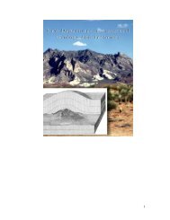
Figure A. Cover photo from AAPG Bulletin (publication <strong>of</strong> Chapter 6)..........................xii<br />
Figure 1.1. Location <strong>and</strong> general <strong>geology</strong> <strong>of</strong> study area...................................................12<br />
Figure 1.2. Generalized stratigraphic column...................................................................14<br />
Figure 1.3. Schematized fault map for Lake Mead region................................................17<br />
Figure 1.4. Photo collage <strong>of</strong> compaction b<strong>and</strong>s in the Aztec s<strong>and</strong>stone...........................20<br />
Figure 1.5. Schematic <strong>of</strong> anticrack conceptual model......................................................23<br />
Figure 1.6. Collection <strong>of</strong> orientation data in the field.......................................................25<br />
Figure 1.7. Located orientation data from Valley <strong>of</strong> Fire.................................................26<br />
Figure 1.8. Orientation data for outcrops with multiple compaction b<strong>and</strong> sets................27<br />
Figure 1.9. Stereographs for combined orientation data...................................................29<br />
Figure 1.10. Stereographs for restored orientation data....................................................32<br />
Figure 1.11. Paleostress orientations <strong>and</strong> interpretation...................................................36<br />
Figure 2.1. Location <strong>of</strong> the Valley <strong>of</strong> Fire State Park, Nevada.........................................41<br />
Figure 2.2. Compaction b<strong>and</strong>s (CBs) in outcrop near Silica Dome..................................43<br />
Figure 2.3. Typical CB fin in outcrop...............................................................................48<br />
Figure 2.4. Compaction b<strong>and</strong> thickness pr<strong>of</strong>ile data.........................................................49<br />
Figure 2.5. Composite photomicrograph <strong>of</strong> a CB.............................................................51<br />
Figure 2.6. Porosity pr<strong>of</strong>iles across a CB..........................................................................52<br />
Figure 2.7. Backscatter electron images <strong>of</strong> s<strong>and</strong>stone <strong>and</strong> a CB......................................53<br />
Figure 2.8. Distribution <strong>of</strong> porosity inside a CB...............................................................55<br />
Figure 2.9. Backscatter electron images <strong>of</strong> grain damage in a CB...................................56<br />
Figure 2.10. Backscatter electron image <strong>of</strong> incipient CB.................................................55<br />
Figure 2.11. Schematic representations <strong>of</strong> idealized CB model.......................................58<br />
Figure 2.12. Near-tip stress components for the embedded layer model..........................65<br />
Figure 2.13. Stress distributions for the Eshelby inclusion model....................................66<br />
Figure 2.14. Stress comparison <strong>of</strong> Eshelby <strong>and</strong> anticrack models....................................69<br />
Figure 2.15. Near-tip stress comparison <strong>of</strong> Eshelby <strong>and</strong> anticrack models......................70<br />
Figure 2.16. Mean normal stress distribution around an anticrack tip..............................70<br />
Figure 3.1. Anatomy <strong>of</strong> a compaction b<strong>and</strong> in the Aztec s<strong>and</strong>stone.................................76<br />
Figure 3.2. Model <strong>of</strong> a semi-infinite CB embedded in an infinite layer...........................79<br />
Figure 3.3. Outcrop basis for the embedded layer CB model...........................................79<br />
Figure 3.4. Hypothetical 1-D distribution <strong>of</strong> stress near a CB tip....................................84<br />
Figure 4.1. Location <strong>of</strong> the Valley <strong>of</strong> Fire State Park, Nevada.........................................87<br />
Figure 4.2. Array <strong>of</strong> subparallel CBs in the Aztec s<strong>and</strong>stone...........................................87<br />
Figure 4.3. Typical compaction b<strong>and</strong> patterns exposed in outcrop..................................90<br />
Figure 4.4. Mechanical interaction between CBs <strong>and</strong> æolian bedding.............................91<br />
Figure 4.5. Tip-to-tip thickness pr<strong>of</strong>ile <strong>of</strong> a 25-m-long CB..............................................91<br />
Figure 4.6. Various CB <strong>propagation</strong> behaviors observed in outcrop................................93<br />
Figure 4.7. Examples <strong>of</strong> tip-to-tip interactions observed in outcrop................................94<br />
Figure 4.8. Composite photomicrograph <strong>of</strong> CB anatomy.................................................95<br />
Figure 4.9. Schematic representations <strong>of</strong> the idealized CB model...................................97<br />
Figure 4.10. Schematic <strong>of</strong> the global <strong>and</strong> anticrack tip coordinate systems.....................99<br />
Figure 4.11. Contour plots <strong>of</strong> near tip stress around an anticrack..................................100<br />
Figure 4.12. Polar near-tip stress as a function <strong>of</strong> θ for a fixed radius...........................102<br />
Figure 4.13. Effect <strong>of</strong> differential stress on <strong>propagation</strong> path stability...........................102<br />
x


