Adaptive View Dependent Tessellation of Displacement Maps
Adaptive View Dependent Tessellation of Displacement Maps
Adaptive View Dependent Tessellation of Displacement Maps

You also want an ePaper? Increase the reach of your titles
YUMPU automatically turns print PDFs into web optimized ePapers that Google loves.
Abstract<br />
To appear in 2000 SIGGRAPH/Eurographics Hardware Workshop<br />
<strong>Adaptive</strong> <strong>View</strong> <strong>Dependent</strong> <strong>Tessellation</strong> <strong>of</strong> <strong>Displacement</strong> <strong>Maps</strong><br />
<strong>Displacement</strong> Mapping is an effective technique for encoding the<br />
high levels <strong>of</strong> detail found in today’s triangle based surface models.<br />
Extending the hardware rendering pipeline to be capable <strong>of</strong> handling<br />
displacement maps as geometric primitives, will allow highly<br />
detailed models to be constructed without requiring large numbers<br />
<strong>of</strong> triangles to be passed from the CPU to the graphics pipeline. We<br />
present a new approach based on recursive tessellation that adapts<br />
to the surface complexity described by the displacement map. We<br />
also ensure that the resolution <strong>of</strong> the displaced mesh is tessellated<br />
with respect to the current view point. Our tessellation scheme performs<br />
all tests only on triangle edges to avoid generating cracks<br />
on the displaced surface. The main decision for vertex insertion is<br />
based on two comparisons involving the average height surrounding<br />
the vertices and the normals at the vertices. Individually, the<br />
tests will fail to tessellate a mesh satisfactorily, but their combination<br />
achieves good results.<br />
We propose several additions to the typical hardware rendering<br />
pipeline in order to achieve displacement map rendering in hardware.<br />
The mesh tessellation is placed within the rendering pipeline<br />
so that we can take advantage <strong>of</strong> the pre-existing vertex transformation<br />
units to perform the setup calculations for our view dependent<br />
test. Our method adds only simple arithmetic and comparison operations<br />
to the graphics pipeline and makes use <strong>of</strong> existing units for<br />
calculations wherever possible.<br />
CR Categories: I.3.1 [Computer Graphics]: Hardware Architecture,<br />
Graphics Processors; I.3.3 [Computer Graphics]: Picture/Image<br />
Generation, Display Algorithms<br />
Keywords: <strong>Displacement</strong> Mapping, Graphics Hardware.<br />
1 Introduction<br />
Three dimensional graphics rendering hardware capable <strong>of</strong> rendering<br />
scenes with a large number <strong>of</strong> polygons is now widely available.<br />
Most systems support texture mapping, which adds surface detail<br />
via a two dimensional colour map that changes the colour at each<br />
pixel on a flat polygonal surface. To make the flat surface look as<br />
though there are small changes in the surface geometry, Blinn introduced<br />
Bump Mapping [1], which is becoming a standard feature<br />
in modern 3D graphics hardware.<br />
¡ e-mail : ¢ miked,jhirche£ @gris.uni-tuebingen.de<br />
Michael Doggett, Johannes Hirche<br />
WSI/GRIS, University <strong>of</strong> Tübingen, Germany<br />
Bump mapping does not really alter the underlying geometry,<br />
but only perturbs the normals on the surface. For small irregularities<br />
on a surface, bump mapping is ideal, since it does not increase<br />
the amount <strong>of</strong> geometry, but gives the impression <strong>of</strong> real textured<br />
surfaces. The limitation <strong>of</strong> bump mapping becomes obvious when<br />
the surface is parallel to the viewer and the Bump does not create a<br />
silhouette. Also as a surface moves in perspective space the shape<br />
created in the viewers mind by the bump map will not occlude other<br />
objects.<br />
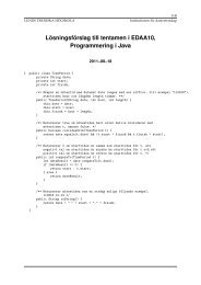
To add real geometric detail to a flat surface, displacement mapping,<br />
first introduced by Cook [2], can be used. As an example Figure<br />
1(a) shows a flat plane with a colour texture applied, which is<br />
displaced using the displacement map in Figure 1(b), where white<br />
represents a high displacement and black represents no displacement.<br />
The application <strong>of</strong> the displacement map to the plane results<br />
in the the displaced surface shown in Figure 1(c). An advantage<br />
<strong>of</strong> using displacement maps is that highly detailed triangle surface<br />
models, such as those generated by 3D scanning technologies, can<br />
be modelled using only a simple base surface and displacement<br />
maps. A compact surface representation using scalar-valued displacements<br />
over a smooth domain surface is presented by Lee [11].<br />
<strong>Displacement</strong> mapping has been used frequently to add geometric<br />
surface detail to objects [17, 12, 9], and is commonly found in commercially<br />
available s<strong>of</strong>tware renders. But unlike bump mapping,<br />
displacement mapping has not been implemented in hardware, due<br />
to the high computational cost.<br />
.<br />
(a) (b) (c)<br />
Figure 1: A plane displaced with a text displacement map.<br />
Adding displacement map rendering to currently available hardware<br />
architectures presents several problems. To apply a displacement<br />
map to a triangle mesh involves re-triangulating the original<br />
mesh and displacing the vertices accordingly. If the base triangle<br />
mesh has a coarser resolution than the displacement map we need<br />
to re-tessellate the mesh according to the surface defined by the<br />
displacement map. This re-tessellation can be performed while rasterizing<br />
the triangle as presented by Doggett and Kugler in [4] and<br />
Gumhold [7]. The problem with these approaches is that either a<br />
large number <strong>of</strong> triangles is generated [4] or new coordinate systems<br />
and complex calculations in a non-standard rasterizer are required<br />
to control the pipeline [7].<br />
We propose to tessellate the individual triangles sequentially by<br />
recursively adding vertices along edges in order to achieve an adaptively<br />
tessellated surface. We check local surface variation between<br />
vertices by comparing normals. At the same time we check the av-
To appear in 2000 SIGGRAPH/Eurographics Hardware Workshop<br />
erage displacement over an area around the vertices to avoid the<br />
¤ aliasing caused by sampling at vertices by using Summed-Area Tables<br />
as presented by Crow [3]. These two tests applied individually<br />
do not generate good results, since the normal test results in aliasing<br />
and the averaged height test misses small details, but the combination<br />
<strong>of</strong> the two tests produces good results. To give the user control<br />
over the size <strong>of</strong> triangles generated with respect to the current view<br />
point, we test the screen size <strong>of</strong> triangles against a user threshold.<br />
This ensures that recursive tessellation will stop when the user does<br />
not require further detail. A displacement map models a discrete<br />
surface which has a limit <strong>of</strong> resolution. We also check if this limit<br />
is reached before generating more triangles, to ensure no more triangles<br />
are generated then there is detail in the original displacement<br />
map.<br />
To minimise the additional hardware required to render displacement<br />
maps, we exploit existing pipeline units wherever possible. A<br />
bump mapping unit is used for displaced surface normal calculation<br />
and extra units are carefully placed within the pipeline to make<br />
use <strong>of</strong> the operations performed by the transformation unit. The<br />
remaining computations only require simple operations such as addition,<br />
division by two and comparisons.<br />
1.1 Previous Work<br />
1.1.1 Bump Mapping<br />
Bump mapping, introduced by Blinn [1], perturbs surface normals<br />
on a surface as if a height field displaced the surface in the direction<br />
<strong>of</strong> the original surface normal. Since bump mapping only changes<br />
the appearance <strong>of</strong> an object, it makes certain approximations. Standard<br />
techniques for bump mapping assume that the bumpiness is<br />
only microdisplacements and hence assume the magnitude <strong>of</strong> the<br />
height field is negligible.<br />
Several hardware based approaches to implementing bump mapping<br />
have been presented in recent years [5, 13, 10]. Peercy presents<br />
an implementation for high-end 3D graphics hardware [13] that<br />
supports bump mapping within the context <strong>of</strong> per-fragment lighting<br />
operations. Kilgard presents an approach to bump mapping that<br />
takes advantage <strong>of</strong> currently available low-cost graphics hardware<br />
in [8]. Although our method requires the use <strong>of</strong> a bump mapping<br />
unit, we will not go into the implementation details in this paper.<br />
1.2 Terrain Modelling<br />
Terrain modelling using height fields is closely related to the rendering<br />
<strong>of</strong> displacement maps. Many algorithms are available for<br />
approximating terrains and height fields using polygonal meshes.<br />
These algorithms approximate the height field with a mesh <strong>of</strong> triangles,<br />
also known as a triangulated irregular network, or TIN. Garland<br />
[6] analyses several <strong>of</strong> these algorithms including the greedy<br />
insertion algorithm. While very good results are achieved these<br />
techniques relie on global mesh information making hardware implementation<br />
expensive.<br />
1.3 <strong>Displacement</strong> Mapping<br />
<strong>Displacement</strong> mapping [2] perturbs a parametric surface along its<br />
normals based on a height field to create a new surface. The base<br />
surface is defined by a bivariate vector function ¥§¦©¨ that defines<br />
3D points ¦© on the surface. The displacements from<br />
the surface are defined by a bivariate scalar ¦©¨ function<br />
<br />
and<br />
. The points on<br />
¦©¨<br />
the new displaced ¥¦©¨ surface are defined as follows<br />
the normals on the base surface ¥§¦©¨ by <br />
<br />
<br />
where<br />
¥ ¦©¨¥§¦©¨¦©¨ <br />
<br />
¦©¨<br />
<br />
.<br />
¦©¨ (1)<br />
2<br />
A cross section <strong>of</strong> an example displacement mapped surface is<br />
shown in Figure 2, where <br />
¦©¨ is the normal to the displaced<br />
<br />
surface.<br />
N’<br />
P’<br />
D<br />
N<br />
P<br />
Figure 2: A cross section <strong>of</strong> a displaced surface.<br />
In Section 2, we describe the calculations required for our adaptive<br />
view dependent tessellation algorithm and in Section 3, we explain<br />
how these operations are implemented in a graphics pipeline.<br />
Section 4 presents the results and Section 5 concludes and presents<br />
future work.<br />
2 <strong>Adaptive</strong> <strong>View</strong> <strong>Dependent</strong> <strong>Tessellation</strong><br />
Our algorithm recursively tessellates the triangles given in the base<br />
mesh or surface ¥§¦©¨ by inserting vertices along edges <strong>of</strong> triangles.<br />
A base triangle that has been recursively adaptively tessellated<br />
to increase the number <strong>of</strong> vertices in the area <strong>of</strong> height change is<br />
shown in Figure 3.<br />
Displaced Surface<br />
Base<br />
Surface<br />
Normal<br />
Base Surface Triangle<br />
Figure 3: A triangle from the base surface is recursively tessellated<br />
to create a displaced surface.<br />
2.1 <strong>Tessellation</strong> based only on edge information<br />
<strong>Displacement</strong> mapping requires a coarse triangle mesh that approximates<br />
the surface to be modelled with a displacement map containing<br />
the finer geometric detail. A re-meshing step is required<br />
to generate a finer mesh that better represents the desired surface.<br />
While many re-meshing algorithms exist [6], few are suitable for<br />
hardware implementation. For example, if tessellation decisions are<br />
based on information local to one triangle then the neighbouring triangles<br />
would need access to this information requiring processing<br />
<strong>of</strong> each triangle to have access to the entire triangle list. Random<br />
access to memory <strong>of</strong> this nature is expensive when implemented in<br />
hardware. To avoid such memory requirements, we limit our vertex<br />
insertion decision to using only the information available within<br />
the current triangle. Furthermore if vertex insertion decisions use<br />
all three vertices <strong>of</strong> a triangle then the common edge between two<br />
adjacent triangles may have a different insertion decision due to the
To appear in 2000 SIGGRAPH/Eurographics Hardware Workshop<br />
third triangle vertex. Vertices inserted along the edge <strong>of</strong> one triangle<br />
but not inserted on the same edge <strong>of</strong> a neighbouring triangle are<br />
known as t-vertices. To avoid cracking in the displaced surface tvertices<br />
must be avoided. To ensure no t-vertices are generated we<br />
limit our vertex insertion decision to information contained in only<br />
the two vertices that subtend the edge in question. The trade<strong>of</strong>f is<br />
that calculations for each edge are performed twice.<br />
Re-meshing is performed by inserting vertices at the midpoint <strong>of</strong><br />
edges if the midpoint meets a series <strong>of</strong> conditions. First the new<br />
vertex ¥ between the two vertices ¥¥ <strong>of</strong> an edge is calculated<br />
by averaging the two vertices. The texture coordinates <br />
and the mesh normal <br />
are similarly calculated. The normal on<br />
the displaced surface, <br />
can be calculated from the original mesh<br />
normal, <br />
and the normal calculated from the displacement map,<br />
, using the bump mapping operations described by Schilling<br />
<br />
[15]. The normal to the displacement ¦©¨ map, can be precomputed<br />
using finite differencing and stored in a normal map in<br />
a similar fashion to values stored in texture maps. The displaced<br />
surfaces and normals are shown in Figure 2.<br />
2.2 Surface Normal Variance Test<br />
Using the new surface normal, <br />
, we compare it’s components<br />
with those <strong>of</strong> the two displaced vertex normals, <br />
and <br />
<br />
¥<br />
<br />
. If<br />
the difference between any <strong>of</strong> the components is greater than a set<br />
threshold, then a vertex is added at (Normal Test). The boolean<br />
value for the Normal Test, is defined as<br />
¦<br />
<br />
<br />
<br />
¦<br />
<br />
<br />
<br />
<br />
¦<br />
<br />
<br />
¦<br />
<br />
<br />
<br />
<br />
<br />
<br />
<br />
<br />
<br />
<br />
<br />
¦<br />
<br />
<br />
<br />
<br />
¦<br />
where is the normal threshold and the symbol represents<br />
the logical or operation.<br />
The Normal Test is subject to aliasing because it uses point sampling<br />
and can easily miss changes in height. A simple example <strong>of</strong><br />
this is shown in Figure 5(a). The advantage <strong>of</strong> the Normal Test is<br />
that it is extremely sensitive to small scale changes in the surface.<br />
The user is required to predetermine the threshold value and<br />
supply this value with the mesh to achieve the required level <strong>of</strong> detail.<br />
2.3 Local Area Average Height Test<br />
To detect average changes in the height <strong>of</strong> the displacement map,<br />
a second test is performed that compares the displacement over<br />
an area using Summed-Area Tables, introduced by Crow [3]. A<br />
Summed-Area Table is a two dimensional array containing at each<br />
cell the sum <strong>of</strong> all values that fall inside the rectangle formed by<br />
that cell and one corner <strong>of</strong> the array. To calculate the sum <strong>of</strong> all<br />
values within a rectangular area in the table only the four values at<br />
the corners <strong>of</strong> the area are needed. The Summed-Area Table can be<br />
represented as a bivariate function ¦© that returns the sum<br />
<strong>of</strong> all heights within the region ( ), where the origin<br />
is in the bottom left <strong>of</strong> the table. The sum <strong>of</strong> the values within a<br />
rectangular area are calculated using the function ¦ defined as<br />
¦© ¦© <br />
¦<br />
¦© (2)<br />
¦©<br />
where is ¦© , the corners <strong>of</strong> the<br />
rectangular area in the Summed-Area Table, using the subscripts<br />
top right, top left, bottom right, bottom left for the four<br />
corners <strong>of</strong> the rectangle .<br />
A Summed-Area Table can be precalculated for the displacement<br />
map and the sum <strong>of</strong> all heights over an area at vertices ¥¥ and<br />
3<br />
can be calculated. To calculate the four corner points <strong>of</strong> the<br />
¥<br />
rectangle around the vertices <strong>of</strong> the edge we use the texture coordinates<br />
at the vertices and as shown in Figure 4. Using<br />
w/4<br />
h/4 P<br />
1<br />
w/2<br />
P 12<br />
h/2<br />
w = u<br />
2<br />
− u<br />
1<br />
h = v − v<br />
2 1<br />
Figure 4: Using the texture coordinates <strong>of</strong> the vertices to calculate<br />
the summed height.<br />
the texture coordinates we can calculate the difference <strong>of</strong> the areas<br />
and compare them with a threshold. This test is called the Summed<br />
Height Test and its boolean value, , is defined as<br />
<br />
<br />
P<br />
2<br />
<br />
¦¦¦ <br />
¦<br />
where is the summed height threshold. This test misses some<br />
cases that the Normal Test detects as shown in Figure 5(b). There<br />
are cases that cannot be detected by both tests. If the displacement<br />
map is highly regular, e.g. high frequency such as a sinusoidal function,<br />
then the Normal Test could always sample identical normals<br />
and the height averaging would cancel itself out. Typically a displacement<br />
map and associated triangle mesh are created together<br />
by the author with the purpose <strong>of</strong> modelling a particular surface<br />
so these cases can be avoided. The combination <strong>of</strong> the Normal<br />
Test and Summed Height Test with appropriate thresholds is capable<br />
<strong>of</strong> re-meshing the small detail in a surface without missing<br />
height changes in smooth surfaces resulting in effective filtering <strong>of</strong><br />
the displacement map.<br />
P’ 1<br />
P’ 12<br />
(a)<br />
P’ 2<br />
P’ 1<br />
P’ 12<br />
Figure 5: The solid line represents a contour line across the displacement<br />
map between the texture coordinates <strong>of</strong> the vertices <strong>of</strong><br />
one edge <strong>of</strong> a triangle with the newly inserted point in the middle.<br />
The dashed lines indicate the area over which the height is averaged<br />
to calculate the Summed Height value. In (a) the Normal Test<br />
fails, but the Summed Height Test succeeds. In (b) the Normal Test<br />
succeeds but the Summed Height Test fails.<br />
2.3.1 <strong>Displacement</strong> Map Filtering<br />
The standard approach for texture filtering is mipmapping as presented<br />
by Williams [16]. This provides an effective means <strong>of</strong> retrieving<br />
levels <strong>of</strong> detail in colour textures that match the screen size<br />
<strong>of</strong> an object. But for displacement mapping, the averaging effect<br />
(b)<br />
P’ 2
To appear in 2000 SIGGRAPH/Eurographics Hardware Workshop<br />
<strong>of</strong> mipmapping will smooth over areas <strong>of</strong> detail in the displacement<br />
map. In [7], they propose to use mipmapping, but with a maximal<br />
filter to overcome this. The Summed Height Test can still miss details<br />
due to averaging over the height, but the normal test will find<br />
these details. And conversely, when the Normal test fails to detect<br />
height change over a smooth surface, the Summed Height Test will<br />
detect the change. This combination results in an effective filtering<br />
<strong>of</strong> the displacement map.<br />
2.4 <strong>View</strong> <strong>Dependent</strong> Resampling<br />
To achieve a view dependent re-sampling that ensures no new triangles<br />
are generated once a certain screen size has been reached, we<br />
perform a test based on the size <strong>of</strong> the current edge in Screen Space.<br />
This test can be performed after the vertices ¥ and ¥ <strong>of</strong> the<br />
current edge are transformed into Screen Space by carefully placing<br />
the re-meshing hardware within an existing graphics pipeline.<br />
Calculating the Euclidean distance requires expensive square and<br />
square root operations, so we only use a Manhattan distance calculation<br />
between the two screen space vertices. This Manhattan<br />
distance is compared with a threshold measured in number <strong>of</strong> pixels.<br />
This test is called the <strong>View</strong> Test and if the Manhattan distance<br />
is greater then a threshold measured in number <strong>of</strong> pixels, then<br />
the boolean value is set to true.<br />
2.5 Refinement Limit Test<br />
Height fields can be rendered by first generating a mesh by inserting<br />
the points defined by the height field into a mesh using algorithms<br />
such as the Greedy Insertion Algorithm [6]. These algorithms pass<br />
over the complete mesh and determine the point <strong>of</strong> maximum error<br />
and insert that point. In the algorithm presented here, we only insert<br />
points calculated from the vertices <strong>of</strong> triangle edges as they are easy<br />
to compute and only depend on the local information <strong>of</strong> a single<br />
edge. If we want to insert points inside a triangle, then the other<br />
vertex in a triangle is required to calculate the interpolated normal<br />
at the point inside the triangle. Another problem occrs when an<br />
adjacent triangle calculates that a point to be inserted is outside its<br />
triangle and is actually inside an adjacent triangle, then the triangle<br />
needs access to the vertex in the adjacent triangle.<br />
The alternative <strong>of</strong> only inserting points on edges leads to the<br />
problem that the points defined by the displacement map are only<br />
approximated and several points might be inserted close to the original<br />
point due to this approximation error. To stop the recursive<br />
algorithm from over inserting points when the original resolution<br />
<strong>of</strong> the displacement map is reached, we perform a test on the texture<br />
coordinates <strong>of</strong> the new point. We compare the integer values<br />
<strong>of</strong> the texture coordinates after they are scaled to the resolution <strong>of</strong><br />
the displacement map. If the value <strong>of</strong> both integer parts <strong>of</strong> the texture<br />
coordinates at the newly inserted vertex are equal to either<br />
<strong>of</strong> the scaled values <strong>of</strong> the two original vertices and , then<br />
the new vertex is not inserted and the boolean value, is set to<br />
false. The test is called the Tex Coord Test. This test stops recursive<br />
subdivision, once the resolution <strong>of</strong> the original displacement map<br />
is reached. We have found that models with areas <strong>of</strong> high variance<br />
<strong>of</strong> the displacement map, such as the hair on the model <strong>of</strong> Volker<br />
Blanz’s head (see Figure 9), can reduce their final triangle counts<br />
by up to 50% by incorporating this simple test.<br />
An alternative to performing the Tex Coord Test is to precalculate<br />
the points on the new surface ¥ ¦©¨ and store them with the<br />
displacement map. These values can then be inserted instead <strong>of</strong><br />
inserting midpoints resulting in a more accurate representation <strong>of</strong><br />
the original displacement map. The problem with this technique is<br />
that the displacement map cannot be interactively scaled because<br />
the new surface has already been pre-calculated.<br />
4<br />
2.6 <strong>Tessellation</strong><br />
Once all the tests have been performed for an edge <strong>of</strong> a triangle<br />
the decision to split the edge is calculated using the following logic<br />
equation<br />
©¦© <br />
where represents the logical or operation and represents the logical<br />
and operation. This © value is calculated for each edge and<br />
depending on the number <strong>of</strong> edges that have to be split an appropriate<br />
tessellation is chosen from Figure 6(a-c). Figure 6(d) shows<br />
two other possibilities for tessellating case 6(c), but we found that<br />
these two triangulations increased the occurance <strong>of</strong> long and thin<br />
triangles so we used the triangulation shown in (c) instead.<br />
(a) (b) (c) (d)<br />
Figure 6: The three triangulations used for tessellation. (a) is used<br />
if three edges are to be split, (b) is used if two edges are split and<br />
(c) is used when one edge is split. (d) Two other possibilities for<br />
splitting two edges that can produce long thin triangles.<br />
2.7 Curved Surface rendering using <strong>Displacement</strong><br />
<strong>Maps</strong><br />
One problem for the rendering <strong>of</strong> displacement maps in hardware is<br />
that modellers are not used to thinking in terms <strong>of</strong> generating models<br />
from displacement maps. In order to handle higher order primitives<br />
such as quadric curves, bezier surfaces and NURBS using<br />
our algorithm, we have incorporated into our displacement mapping<br />
s<strong>of</strong>tware simulation the capability to sample a quadric surface<br />
and render it using displacement mapping. The current s<strong>of</strong>tware<br />
implementation has only limited capabilities, since it can only render<br />
NURBS which only elevate their parameter space.<br />
The only information that can be stored in the NURBS surface is<br />
the height or displacement from a base mesh. Applied to a suitable<br />
base mesh, this already provides enormous flexibility for designing<br />
and modelling by exploiting the high triangle performance <strong>of</strong> available<br />
graphics cards. Although this sampling approach uses the host<br />
to compute the displacement map, it would be relatively straightforward<br />
to couple a hardware implementation <strong>of</strong> a curved surface evaluation<br />
– like that used in the OpenGL pipeline proposed by Rockwood<br />
[14] – with our hardware design, if they become available<br />
in the future. This would enable the rendering <strong>of</strong> curved surface<br />
models at high speed and without the need for new and expensive<br />
scanline converters.<br />
3 Hardware Architecture<br />
To realise hardware rendering <strong>of</strong> displacement maps, we suggest<br />
the introduction <strong>of</strong> several units into a standard rendering pipeline<br />
such as the OpenGL pipeline [18]. These new units and their positioning<br />
relative to the usual units in a pipeline are shown in Figure<br />
7. The OpenGL Clipping, Perspective, and <strong>View</strong>port Application
To appear in 2000 SIGGRAPH/Eurographics Hardware Workshop<br />
stage is represented by our Transform stage. The OpenGL pipeline<br />
places Lighting inside the Vertices operations unit before transformation<br />
to screen space to achieve per-vertex lighting. Modern<br />
implementations <strong>of</strong> the graphics pipeline such as NVIDIA’s GPUs<br />
place the lighting calculations after the transformation to improve<br />
per-fragment lighting capabilities. We have also moved the Lighting<br />
stage after the Transform stage, to allow our re-meshing and<br />
normal calculations to occur in world space.<br />
We add four new units to the graphics pipeline including a Get<br />
Triangle, Calculate New P, Displace Vertex, <strong>Tessellation</strong> Tests and<br />
<strong>Tessellation</strong> stage. Also storage for the displacement map and a<br />
triangle queue are added at the top level. The Get Triangle Unit is<br />
responsible for retrieving triangles from either the host CPU or the<br />
Triangle Queue. The Get Triangle Unit also checks which vertices<br />
and normals <strong>of</strong> incoming triangles have already been transformed<br />
into screen space and only sends the new vertices and their normals<br />
through the Transform unit.<br />
The Calculate New P stage takes two vertices <strong>of</strong> a triangle and<br />
averages them to find the midpoint. This midpoint passes through<br />
the Displace Vertex stage which calculates the new surface point<br />
¦ as defined in Equation 1. This requires reading the dis-<br />
¥<br />
placement from the displacement map, multiplying it by the surface<br />
<br />
<br />
normal and adding the result to the current surface point<br />
. This operation is only performed for new vertices which are<br />
¥<br />
extracted from the current triangle information by the Get Triangle<br />
stage. Once the displacement is performed, the newly displaced<br />
vertex is passed through the Transform stage and transformed into<br />
screen space. The <strong>Tessellation</strong> stage takes the vertex information<br />
<strong>of</strong> the current triangle, the new vertices to be inserted, and constructs<br />
new triangles based on the triangulations shown in Section<br />
2.6. These new triangles are inserted into the Triangle Queue, a<br />
FIFO queue, where they are read back into the pipeline by the Get<br />
Triangle unit. The Triangle Queue requires either on-chip memory<br />
or <strong>of</strong>f-chip memory requiring an additional reading and writing<br />
unit. Either implementation is a significant requirement for this algorithm.<br />
3.1 <strong>Tessellation</strong> Tests Architecture<br />
The <strong>Tessellation</strong> Tests unit calculates new texture coordinates and<br />
normals and the four edge tests. The unit is pipelined and each new<br />
vertex, ¥¥ and ¥ , is sent through the pipeline sequentially,<br />
requiring only one pipeline. If faster performance was required due<br />
to multiple Transform pipelines then the unit could be replicated<br />
three times. The architecture <strong>of</strong> the <strong>Tessellation</strong> Tests unit is shown<br />
in Figure 8 with inputs and outputs labelled for testing the edge<br />
between vertices ¥ and ¥ .<br />
3.1.1 <strong>View</strong> Test<br />
The simplest test in the <strong>Tessellation</strong> Tests is the <strong>View</strong> Test. This<br />
test is done in screen space by calculating the Manhattan distance<br />
for the current edge using the displaced transformed vertices. For<br />
triangles that are being re-tessellated, the transformed vertex values<br />
will have already been calculated in the previous pass, so this data<br />
will be immediately available. But for new triangles, this stage will<br />
have to wait until the values are available after the Transform stage.<br />
This waiting time can be easily accommodated, since for each new<br />
triangle the tests must wait until not only the original vertices are<br />
transformed, but also the newly inserted vertices are transformed.<br />
Also the ratio <strong>of</strong> new triangles to re-tessellated triangles is quite low<br />
so this wait time will happen infrequently. The result <strong>of</strong> the <strong>View</strong><br />
Test, is passed to the Pass or Tessellate unit.<br />
5<br />
3.1.2 Tex Coord Test<br />
The calculation <strong>of</strong> the texture coordinates for the new vertices is<br />
required by several subsequent units. The Calculate New U calculates<br />
the new texture coordinates using an add and division by two.<br />
The integer part <strong>of</strong> the new texture coordinate up to the resolution<br />
<strong>of</strong> the displacement map are compared with the integer part <strong>of</strong> the<br />
original texture coordinates <strong>of</strong> the edge’s vertices. The test is calculated<br />
by the Tex Coord Test unit and the result passed onto the Pass<br />
or Tessellate unit.<br />
3.1.3 Summed Height Test<br />
The new texture coordinates are used by the Height Test to look<br />
up and calculate an average height from the Summed Height Table.<br />
First the difference between the texture coordinates at the vertices<br />
are calculated and divided by 4 and 8 using logical shift operations.<br />
The results are combined with the vertex texture coordinates to calculate<br />
the four values required to access the Summed Height Table.<br />
The calculation <strong>of</strong> the average height for each point using the<br />
Summed Height Table will take four cycles since each value must<br />
be read and combined using Equation 2. The values are then combined<br />
and divided according to the Summed Height Test and the<br />
difference compared with the shthr to determine if there is a significant<br />
change in height. The result is passed to the Pass or Tessellate<br />
unit.<br />
3.1.4 Normal Test<br />
The other operation <strong>of</strong> the <strong>Tessellation</strong> Tests unit is the Normal Test.<br />
This test requires first the calculation <strong>of</strong> the new normal <br />
using <br />
an add and division by two. Then the new normal must be normalised<br />
before being bump mapped. Normalisation is an expensive<br />
operation, but implementations are available in most graphics<br />
pipelines. Then using the new texture coordinates, the normal<br />
to the displacement <br />
is read from a precomputed normal map.<br />
The new surface normal, <br />
is calculated by perturbing the sur-<br />
<br />
face normal, <br />
, by the displacement map normal, <br />
, using<br />
a bump mapping hardware unit. As mentioned earlier several approaches<br />
to bump mapping have been proposed and could be used<br />
to provide the operation required here. After calculating the new<br />
displaced surface normal its components are subtracted from those<br />
<strong>of</strong> the normals from the displaced vertices <br />
. The differ- <br />
and <br />
ence is compared to resulting in the boolean value which<br />
is passed to the Pass or Tessellate unit.<br />
3.1.5 Pass or Tessellate Unit<br />
The Pass or Tessellate unit combines the results <strong>of</strong> the four tests to<br />
determine if the edge is to be split. If the edge is to be split then the<br />
new vertex ¥ is indicated for insertion into the current triangle<br />
to the <strong>Tessellation</strong> unit. For each vertex that was part <strong>of</strong> the origi-<br />
nal triangle, the Pass or Tessellate unit passes the following set <strong>of</strong><br />
values to the <strong>Tessellation</strong> unit ¥¥ : where the<br />
<br />
<br />
<br />
<br />
subscript means the vector is in world space and the subscript<br />
means the vector is in screen space. For the newly inserted vertices,<br />
it has all <strong>of</strong> the above values except the <br />
value which is calcu-<br />
<br />
lated on the triangles next pass through the pipeline. If the triangle<br />
has no new vertices to insert then only the following values are sent<br />
to the Lighting ¥ <br />
<br />
unit<br />
also perform backface culling on the new triangles since they have<br />
been generated with screen space normal values.<br />
The most complex unit in the <strong>Tessellation</strong> Tests unit are those<br />
required for the Normal Test which include a bump mapping operation<br />
and a normalisation. Both units exist in most graphics pipelines<br />
and can be expected in most pipelines in the future. Also memory<br />
and a controller for the buffering in the Triangle Queue is required.<br />
. The Pass or Tessellate unit can
Triangle<br />
Queue<br />
Get<br />
Calculate<br />
To appear in 2000 SIGGRAPH/Eurographics Hardware Workshop<br />
Displace<br />
Triangle New P Vertex<br />
<strong>Displacement</strong><br />
Map<br />
Transform<br />
<strong>Tessellation</strong><br />
<strong>Tessellation</strong><br />
Tests<br />
Lighting<br />
Raster−<br />
ization<br />
Figure 7: A graphics pipeline with new units added to perform displacement map rendering.<br />
The other units only require addition, subtraction, divisions by powers<br />
<strong>of</strong> two, compare operations and other logic functions. The latency<br />
involved in the <strong>Tessellation</strong> Tests unit can be compensated by<br />
the latency <strong>of</strong> the Transform unit since both pipelines run in parallel.<br />
The major additional latency to the overall graphics pipeline is<br />
in the Displace Vertex unit which requires a multiply and accumulate.<br />
4 Results<br />
To demonstrate the effectiveness <strong>of</strong> our adaptive tessellation algorithm,<br />
we have implemented the architecture in Figure 7 and Figure<br />
8 using a s<strong>of</strong>tware simulation. To take advantage <strong>of</strong> OpenGL functionality,<br />
we use the feedback render mode to perform the transform<br />
calculations. We have rendered several models with our technique<br />
to demonstrate the range <strong>of</strong> datasets that it can handle and possibilities<br />
provided by displacement mapping.<br />
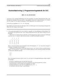
To demonstrate the adaptive nature <strong>of</strong> the tessellation and the<br />
effectiveness <strong>of</strong> combining the Normal Test and Summed Height<br />
Test, a flat plane consisting <strong>of</strong> only 18 triangles was displaced with a<br />
half donut displacement as shown in Figure 10. In Figure 10(a), we<br />
can see the aliasing errors associated with the Normal Test, while in<br />
Figure 10(b), some edges have not been split because the averaging<br />
effect <strong>of</strong> the Summed Height Test has not detected the local change<br />
in surface orientation. The combination <strong>of</strong> the two tests is shown<br />
in Figure 10(c) where both the local surface orientation and average<br />
change in height is detected producing an adaptively tessellated<br />
displaced surface.<br />
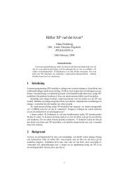
The view dependent capabilities <strong>of</strong> our algorithm are demonstrated<br />
using a cyberware scanner model <strong>of</strong> Volker Blanz’s head.<br />
The scanner generates a texture and displacement map parametrised<br />
in cylindrical coordinates with a resolution <strong>of</strong> <br />
use a cylinder for a base mesh consisting <strong>of</strong> 1800 triangles. The<br />
model rendered at three different distances from the view point is<br />
shown in Figure 9. In Figures 9(a,b,c), the image rendered shows<br />
the distance <strong>of</strong> the model from the view plane. In Figures 9(d,e,f), a<br />
wireframe close-up <strong>of</strong> the region around the nose, eyes and mouth<br />
using the respective meshes from (a,b,c), can be seen. In Figure<br />
<br />
texels. We<br />
6<br />
Frame<br />
Buffer<br />
9(d) the high level <strong>of</strong> detail can be seen in the tessellation around<br />
the eye including the eye brow. Both the view dependent tessellation<br />
as well as the effective adaptive techniques are demonstrated.<br />
The adaptive nature <strong>of</strong> the algorithm can be seen in the level <strong>of</strong><br />
detail around the nose, eyes and mouth where there is increased<br />
surface detail.<br />
To evaluate the algorithm on terrain models, we used the Crater<br />
Lake (West half <strong>of</strong> Crater Lake, Oregon) Digital Elevation Map<br />
(DEM), which has dimensions <strong>of</strong> <br />
Figure 11(a) we can see that a small island inside the crater and the<br />
edge <strong>of</strong> the crater is represented with a high level <strong>of</strong> detail, while<br />
the water level in the crater is left at the resolution <strong>of</strong> the original<br />
mesh.<br />
An example <strong>of</strong> the donut displacement map applied to the wellknown<br />
Utah teapot is shown in Figure 11(b). We are also investigating<br />
the possibilities <strong>of</strong> saving the mesh state from one displacement<br />
map and adding another displacement to it as shown in Figure 11(c)<br />
where the base donut is a displacement map. While this works in<br />
our s<strong>of</strong>tware simulation we are still considering the hardware implications<br />
<strong>of</strong> such an operation.<br />
5 Conclusions and Future work<br />
<br />
from Garland [6]. In<br />
In this paper, we have proposed additional units for a standard<br />
graphics pipeline to enable the rendering <strong>of</strong> displacement maps in<br />
hardware. Our technique encompasses adaptive view dependent remeshing,<br />
driven by the displacement map’s surface complexity and<br />
user defined thresholds. The additions to the hardware pipeline<br />
would only require standard features such as bump mapping and<br />
simple arithmetic units. We have tested our algorithm on several<br />
real and synthetic datasets and it is capable <strong>of</strong> generating low triangle<br />
count meshes, by adaptively subdividing triangles. Our tessellation<br />
scheme takes into account several factors including displacement,<br />
surface variation, view point and original mesh resolution.<br />
Backface culling cannot be applied to the original base mesh,<br />
because the displacement might generate triangles that are visible.<br />
Our tessellation results in normals in screen space, so backface<br />
culling can be applied after tessellation and before rasterization.
P’ 1 P’ 2<br />
U1<br />
U2<br />
N1 N2<br />
N’ 1 N’ 2<br />
Calculate<br />
New U<br />
Calculate<br />
New N<br />
To appear in 2000 SIGGRAPH/Eurographics Hardware Workshop<br />
U 12<br />
N 12<br />
Normal<br />
Map<br />
Bump<br />
Map<br />
N D12<br />
N’ 12<br />
Our combination <strong>of</strong> the Normal Test with the Summed Height Test<br />
also provides an effective filter for the displacement map, which is<br />
not possible using maximal valued mipmapping. Using displacement<br />
mapping as a rendering primitive can significantly reduce the<br />
bottleneck <strong>of</strong> sending triangle data to the graphics engine. As displacement<br />
maps are used increasingly to model the geometric detail<br />
on surfaces, hardware support for rendering these displacement<br />
maps will become a sought-after feature in graphics accelerators.<br />
5.1 Future work<br />
There are several avenues <strong>of</strong> future work that are possible from<br />
what has been presented in this paper. Scaling the displacement<br />
map by introducing a scaling factor into equation 1 is done as fol-<br />
¥¦©¨§¥§¦©¨¦©¨ <br />
<br />
¦©¨ lows . The capability to<br />
scale the displacement map already exists within our s<strong>of</strong>tware simulation,<br />
but requires that the displacement value used in the Displace<br />
Vertex unit is appropriately scaled and that the normal map is<br />
calculated using finite differences and is normalised for each new<br />
scale value <strong>of</strong> the displacement map. We are currently investigating<br />
the implementation details for this extension to our approach.<br />
Another interesting extension to our work includes tests on the surface<br />
normals to determine which triangles are located within or near<br />
the Phong highlight to improve the tessellation <strong>of</strong> these area when<br />
per-vertex lighting schemes are used.<br />
Acknowledgements<br />
This work has been funded by the SFB grant 382 <strong>of</strong> the German Research<br />
Council (DFG). Thanks to Anders Kugler, Michael Meißner,<br />
<strong>View</strong><br />
Test<br />
TexCoord<br />
Test<br />
Height<br />
Test<br />
Normal<br />
Test<br />
vthr<br />
nthr<br />
Summed<br />
shthr<br />
Height<br />
Table<br />
Figure 8: Architecture for the <strong>Tessellation</strong> Tests unit.<br />
7<br />
Pass or<br />
Tessellate<br />
Dirk Bartz, Urs Kanus and Andreas Schilling for pro<strong>of</strong>-reading and<br />
helpful discussions. Thanks to Volker Blanz for use <strong>of</strong> the digitized<br />
model <strong>of</strong> his head.<br />
References<br />
[1] Jim Blinn. Jim Blinn’s Corner: A Trip down the graphics<br />
pipeline. Morgan Kaufmann, 1996. Chapter 17: Hyperbolic<br />
Interpolation.<br />
[2] Robert L. Cook. Shade Trees. Computer Graphics (Proceedings<br />
<strong>of</strong> SIGGRAPH 84), 18(3):223–231, July 1984. Held in<br />
Minneapolis, Minnesota.<br />
[3] Franklin C. Crow. Summed-Area Tables for Texture Mapping.<br />
Computer Graphics (Proceedings <strong>of</strong> SIGGRAPH 84),<br />
18(3):207–212, July 1984. Held in Minneapolis, Minnesota.<br />
[4] Michael Doggett and Anders Kugler. A Hardware Architecture<br />
for <strong>Displacement</strong> Mapping using Scan Conversion. Technical<br />
Report WSI–99–12, Wilhelm-Schickard-Institut für Informatik,<br />
University <strong>of</strong> Tübingen, Germany, 1999.<br />
[5] I. Ernst, D. Jackél, H. Rüsseler, and O. Wittig. Hardwaresupported<br />
bump mapping. Computers and Graphics,<br />
20(4):515–521, 1996.<br />
[6] Michael Garland and Paul S. Heckbert. Fast polygonal approximation<br />
<strong>of</strong> terrains and height fields. Technical Report<br />
CMU-CS-95-181, Carnegie Mellon University, 1995.
To appear in 2000 SIGGRAPH/Eurographics Hardware Workshop<br />
[7] Stefan Gumhold and Tobias Hüttner. Multiresolution rendering<br />
with displacement mapping. In Eurographics/SIGGRAPH<br />
Workshop on Graphics Hardware, pages 55–66, August 1999.<br />
[8] Mark J. Kilgard. A Practical and Robust Bump-Mapping<br />
Technique for Today’s GPUs. Technical report, NVIDIA Corporation,<br />
www.nvidia.com, February 2000.<br />
[9] Venkat Krishnamurthy and Marc Levoy. Fitting smooth surfaces<br />
to dense polygon meshes. Proceedings <strong>of</strong> SIGGRAPH<br />
96, pages 313–324, August 1996. ISBN 0-201-94800-1. Held<br />
in New Orleans, Louisiana.<br />
[10] Anders Kugler. IMEM: an intelligent memory for bump- and<br />
reflection-mapping. In Eurographics/SIGGRAPH Workshop<br />
on Graphics Hardware, pages 113–122, August 1998.<br />
[11] Aaron Lee, Henry Moreton, and Hugues Hoppe. Displaced<br />
subdivision surfaces. In Computer Graphics, Proc. <strong>of</strong> SIG-<br />
GRAPH 2000. ACM, 2000.<br />
[12] Kazunori Miyata. A method <strong>of</strong> generating stone wall patterns.<br />
In Computer Graphics, Proc. <strong>of</strong> SIGGRAPH 90, pages 387–<br />
394. ACM, 1990.<br />
[13] Mark Peercy, John Airey, and Brian Cabral. Efficient bump<br />
mapping hardware. In Computer Graphics, Proc. <strong>of</strong> SIG-<br />
GRAPH 97, pages 303–306. ACM, 1997.<br />
[14] Alyn P. Rockwood, Kurt Heaton, and Tom Davis. Real-time<br />
rendering <strong>of</strong> trimmed surfaces. Computer Graphics (Proceedings<br />
<strong>of</strong> SIGGRAPH 89), 23(3):107–116, July 1989. Held in<br />
Boston, Massachusetts.<br />
[15] Andreas Schilling. Towards real-time photorealistic rendering:<br />
Challenges and solutions. In Eurographics/SIGGRAPH<br />
Workshop on Graphics Hardware, pages 7–15, August 1997.<br />
[16] Lance Williams. Pyramidal Parametrics. In Computer Graphics,<br />
Proc. <strong>of</strong> SIGGRAPH 83. ACM, 1983.<br />
[17] Andrew Witkin and Michael Kass. Reaction-diffusion textures.<br />
In Thomas W. Sederberg, editor, Computer Graphics<br />
(SIGGRAPH ’91 Proceedings), volume 25, pages 299–308,<br />
July 1991.<br />
[18] Mason Woo, Jackie Neider, and Tom Davis. OpenGL Programming<br />
Guide. Addison Wesley, 1997.<br />
8
To appear in 2000 SIGGRAPH/Eurographics Hardware Workshop<br />
(a) (d) (a)<br />
(b) (e) (b)<br />
(c) (f) (c)<br />
Figure 9: Volker’s head dataset. (a), (b) and (c) show distance<br />
from view plane, (d), (e) and (f) are mesh close-ups for corresponding<br />
images.<br />
Figure 10: (a) Normal Test only. (b) Summed<br />
Height Test only. (c) Both tests.<br />
(a) (b) (c)<br />
Figure 11: (a) The Crater Lake. (b) A half donut displaced teapot (c) The half donut with texture and more surface detail added using<br />
another displacement map.<br />
9