


Create successful ePaper yourself
Turn your PDF publications into a flip-book with our unique Google optimized e-Paper software.
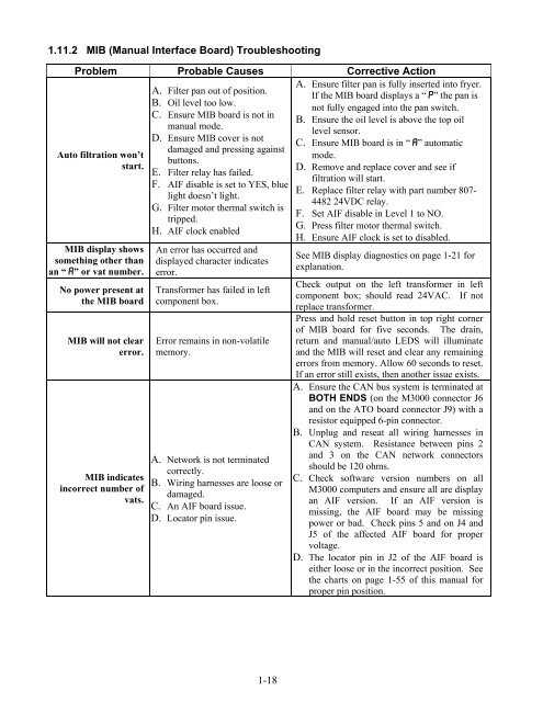
1.11.2 MIB (Manual Interface Board) Troubleshooting<br />
Problem Probable Causes Corrective Action<br />
Auto filtration won’t<br />
start.<br />
MIB display shows<br />
something other than<br />
an “A” or vat number.<br />
No power present at<br />
the MIB board<br />
MIB will not clear<br />
error.<br />
MIB indicates<br />
incorrect number of<br />
vats.<br />
A. Filter pan out of position.<br />
B. Oil level too low.<br />
C. Ensure MIB board is not in<br />
manual mode.<br />
D. Ensure MIB cover is not<br />
damaged and pressing against<br />
buttons.<br />
E. Filter relay has failed.<br />
F. AIF disable is set to YES, blue<br />
light doesn’t light.<br />
G. Filter motor thermal switch is<br />
tripped.<br />
H. AIF clock enabled<br />
An error has occurred and<br />
displayed character indicates<br />
error.<br />
Transformer has failed in left<br />
component box.<br />
Error remains in non-volatile<br />
memory.<br />
A. Network is not terminated<br />
correctly.<br />
B. Wiring harnesses are loose or<br />
damaged.<br />
C. An AIF board issue.<br />
D. Locator pin issue.<br />
1-18<br />
A. Ensure filter pan is fully inserted into fryer.<br />
If the MIB board displays a “P” the pan is<br />
not fully engaged into the pan switch.<br />
B. Ensure the oil level is above the top oil<br />
level sensor.<br />
C. Ensure MIB board is in “A” automatic<br />
mode.<br />
D. Remove and replace cover and see if<br />
filtration will start.<br />
E. Replace filter relay with part number 807-<br />
4482 24VDC relay.<br />
F. Set AIF disable in Level 1 to NO.<br />
G. Press filter motor thermal switch.<br />
H. Ensure AIF clock is set to disabled.<br />
See MIB display diagnostics on page 1-21 for<br />
explanation.<br />
Check output on the left transformer in left<br />
component box; should read 24VAC. If not<br />
replace transformer.<br />
Press and hold reset button in top right corner<br />
of MIB board for five seconds. The drain,<br />
return and manual/auto LEDS will illuminate<br />
and the MIB will reset and clear any remaining<br />
errors from memory. Allow 60 seconds to reset.<br />
If an error still exists, then another issue exists.<br />
A. Ensure the CAN bus system is terminated at<br />
BOTH ENDS (on the M3000 connector J6<br />
and on the ATO board connector J9) with a<br />
resistor equipped 6-pin connector.<br />
B. Unplug and reseat all wiring harnesses in<br />
CAN system. Resistance between pins 2<br />
and 3 on the CAN network connectors<br />
should be 120 ohms.<br />
C. Check software version numbers on all<br />
M3000 computers and ensure all are display<br />
an AIF version. If an AIF version is<br />
missing, the AIF board may be missing<br />
power or bad. Check pins 5 and on J4 and<br />
J5 of the affected AIF board for proper<br />
voltage.<br />
D. The locator pin in J2 of the AIF board is<br />
either loose or in the incorrect position. See<br />
the charts on page 1-55 of this manual for<br />
proper pin position.


