


Create successful ePaper yourself
Turn your PDF publications into a flip-book with our unique Google optimized e-Paper software.
1.10.3 Replacing the ATO board, LON Gateway, ATO pump relay or Transformers<br />
Disconnect the fryer from the electrical power<br />
supply. Locate the ATO box (see Figure 1 on page<br />
12), behind the JIB (Jug In Box). Remove the cover<br />
to expose the transformers, relay and LON gateway<br />
(if installed) (see Figure 2). Mark and unplug any<br />
wires or harnesses. Once the LON gateway is<br />
removed the ATO board is visible (see Figure 3).<br />
Replace the defective component and reattach all<br />
wires or harnesses. Replace the cover. Once<br />
replaced, CYCLE POWER TO ENTIRE FRYER<br />
SYSTEM. See section 1.11.7 on page 1-22 to reset<br />
control power. Check software version and if<br />
necessary update the software. If a software update<br />
was necessary, follow the instructions to update the<br />
software in section 1.15<br />
1-16<br />
Figure 2 Figure 3<br />
Press the TEMP button on one of the M3000 computers, with the computer in the OFF position, to verify<br />
software version of the ATO. If the version is not visible, the ATO may not be connected properly.<br />
1.10.4 Replacing the ATO Pump<br />
Disconnect the fryer from the electrical power<br />
supply. Locate the ATO pump (see Figure 4), behind<br />
the ATO box. Mark and unplug any wires or<br />
harnesses. Press up from the bottom on the quick<br />
disconnects to release the plumbing (see Figure 5).<br />
The plumbing can be pulled from the pump. Loosen<br />
the four nuts attaching the pump to the pump tray.<br />
Replace the defective component and reverse above<br />
steps. Once replaced, reconnect the power.<br />
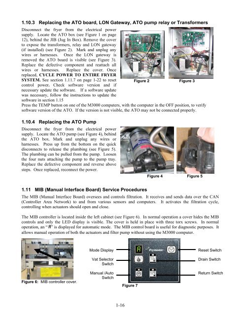
1.11 MIB (Manual Interface Board) Service Procedures<br />
Figure 4 Figure 5<br />
The MIB (Manual Interface Board) oversees and controls filtration. It receives and sends data over the CAN<br />
(Controller Area Network) to and from various sensors and computers. It activates the filtration cycle,<br />
controlling when actuators should open and close.<br />
The MIB controller is located inside the left cabinet (see Figure 6). In normal operation a cover hides the MIB<br />
controls and only the LED display is visible. The cover is held in place with three torx screws. In normal<br />
operation, an “A” is displayed for automatic mode. The MIB control board is useful for diagnostic purposes. It<br />
allows manual operation of both the actuators and filter pump without using the M3000 computer.<br />
Figure 6: MIB controller cover.<br />
Mode Display<br />
Vat Selector<br />
Switch<br />
Manual /Auto<br />
Switch<br />
Figure 7<br />
Reset Switch<br />
Drain Switch<br />
Return Switch


