


Create successful ePaper yourself
Turn your PDF publications into a flip-book with our unique Google optimized e-Paper software.
8. Reconnect the element connector ensuring that the latches lock.<br />
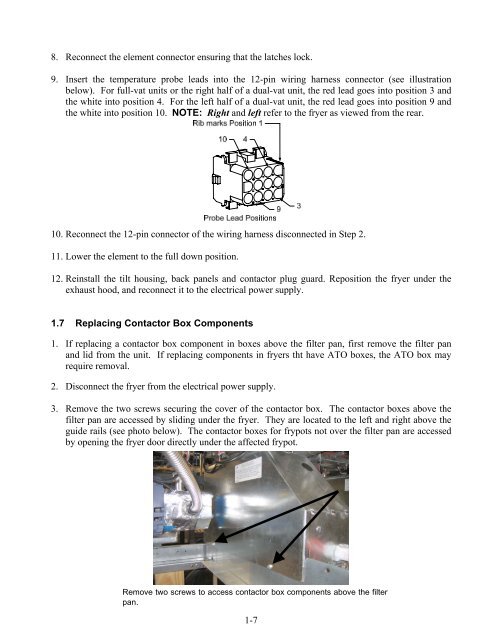
9. Insert the temperature probe leads into the 12-pin wiring harness connector (see illustration<br />
below). For full-vat units or the right half of a dual-vat unit, the red lead goes into position 3 and<br />
the white into position 4. For the left half of a dual-vat unit, the red lead goes into position 9 and<br />
the white into position 10. NOTE: Right and left refer to the fryer as viewed from the rear.<br />
10. Reconnect the 12-pin connector of the wiring harness disconnected in Step 2.<br />
11. Lower the element to the full down position.<br />
12. Reinstall the tilt housing, back panels and contactor plug guard. Reposition the fryer under the<br />
exhaust hood, and reconnect it to the electrical power supply.<br />
1.7 Replacing Contactor Box Components<br />
1. If replacing a contactor box component in boxes above the filter pan, first remove the filter pan<br />
and lid from the unit. If replacing components in fryers tht have ATO boxes, the ATO box may<br />
require removal.<br />
2. Disconnect the fryer from the electrical power supply.<br />
3. Remove the two screws securing the cover of the contactor box. The contactor boxes above the<br />
filter pan are accessed by sliding under the fryer. They are located to the left and right above the<br />
guide rails (see photo below). The contactor boxes for frypots not over the filter pan are accessed<br />
by opening the fryer door directly under the affected frypot.<br />
Remove two screws to access contactor box components above the filter<br />
pan.<br />
1-7


