


Create successful ePaper yourself
Turn your PDF publications into a flip-book with our unique Google optimized e-Paper software.
1.6 Replacing a Heating Element<br />
1. Perform steps 1-5 of section 1.5, Replacing a Temperature Probe.<br />
2. Disconnect the wire harness containing the probe wiring, where the temperature probe is attached<br />
to the element being replaced. Using a pin pusher, disconnect the probe wires from the 12-pin<br />
connector.<br />
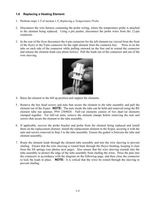
3. In the rear of the fryer disconnect the 6-pin connector for the left element (as viewed from the front<br />
of the fryer) or the 9-pin connector for the right element from the contactor box. Press in on the<br />
tabs on each side of the connector while pulling outward on the free end to extend the connector<br />
and release the element leads (see photo below). Pull the leads out of the connector and out of the<br />
wire sleeving.<br />
4. Raise the element to the full up position and support the elements.<br />
5. Remove the hex head screws and nuts that secure the element to the tube assembly and pull the<br />
element out of the frypot. NOTE: The nuts inside the tube can be held and removed using the RE<br />
element tube nut spanner, PN# 2304028. Full-vat elements consist of two dual-vat elements<br />
clamped together. For full-vat units, remove the element clamps before removing the nuts and<br />
screws that secure the element to the tube assembly.<br />
6. If applicable, recover the probe bracket and probe from the element being replaced and install<br />
them on the replacement element. Install the replacement element in the frypot, securing it with the<br />
nuts and screws removed in Step 5 to the tube assembly. Ensure the gasket is between the tube and<br />
element assembly.<br />
7. Route the element leads through the element tube assembly and into the wire sleeving to prevent<br />
chafing. Ensure that the wire sleeving is routed back through the Heyco bushing, keeping it clear<br />
from the lift springs (see photos next page). Also ensure that the wire sleeving extends into the<br />
tube assembly to protect the edge of the tube assembly from chafing the wires. Press the pins into<br />
the connector in accordance with the diagram on the following page, and then close the connector<br />
to lock the leads in place. NOTE: It is critical that the wires be routed through the sleeving to<br />
prevent chafing.<br />
1-5


