The Windward Performance of Yachts in Rough Water - Centre for ...
The Windward Performance of Yachts in Rough Water - Centre for ...
The Windward Performance of Yachts in Rough Water - Centre for ...

You also want an ePaper? Increase the reach of your titles
YUMPU automatically turns print PDFs into web optimized ePapers that Google loves.
<strong>The</strong> <strong>W<strong>in</strong>dward</strong> <strong>Per<strong>for</strong>mance</strong> <strong>of</strong> <strong>Yachts</strong> <strong>in</strong> <strong>Rough</strong> <strong>Water</strong><br />
14th Chesapeake Sail<strong>in</strong>g Yacht Symposium<br />
January 30, 1999<br />
Jonathan R. B<strong>in</strong>ns, Australian Maritime Eng<strong>in</strong>eer<strong>in</strong>g Cooperative Research <strong>Centre</strong> Ltd. (AME CRC)<br />
Bruce McRae, Australian Maritime Eng<strong>in</strong>eer<strong>in</strong>g Cooperative Research <strong>Centre</strong> Ltd. (AME CRC)<br />
Giles Thomas, Australian Maritime Eng<strong>in</strong>eer<strong>in</strong>g Cooperative Research <strong>Centre</strong> Ltd. (AME CRC)<br />
ABSTRACT<br />
A 5 year research program to <strong>in</strong>vestigate the<br />
effect <strong>of</strong> realistic hull <strong>for</strong>m parameters on the added<br />
resistance <strong>of</strong> a yacht <strong>in</strong> waves is near<strong>in</strong>g completion.<br />
Model experiments and theoretical predictions were<br />
carried out and the results are discussed <strong>in</strong> this paper.<br />
Five hull <strong>for</strong>m parameters have been <strong>in</strong>vestigated<br />
so far, they are: 1. stern overhang; 2. LCB-LCF<br />
separation; 3. prismatic coefficient, 4. displacement<br />
length ratio and 5. beam draft ratio.<br />
NOTATION<br />
CP Prismatic coefficient<br />
Cts Total resistance coefficient, <strong>for</strong> calm water<br />
LCB Longitud<strong>in</strong>al <strong>Centre</strong> <strong>of</strong> Buoyancy<br />
LCF Longitud<strong>in</strong>al <strong>Centre</strong> <strong>of</strong> Flotation<br />
Lwl Length, waterl<strong>in</strong>e<br />
RAO Response Amplitude Operator<br />
V Yacht velocity, (m/s)<br />
VPP Velocity Prediction Program<br />
INTRODUCTION<br />
<strong>The</strong> aim <strong>of</strong> this jo<strong>in</strong>t Australian Maritime<br />
Eng<strong>in</strong>eer<strong>in</strong>g Cooperative Research <strong>Centre</strong> (AME CRC)<br />
and Murray, Burns & Dovell (MBD) project was to<br />
develop a VPP module which calculates the added<br />
resistance <strong>of</strong> a yacht <strong>in</strong> waves from theoretical<br />
predictions and tow<strong>in</strong>g tank experiments. <strong>The</strong> RAO <strong>of</strong><br />
the added resistance is obta<strong>in</strong>ed by divid<strong>in</strong>g the added<br />
resistance <strong>of</strong> the yacht <strong>in</strong> waves by the square <strong>of</strong> wave<br />
amplitude.<br />
<strong>The</strong> International Measurement System (IMS)<br />
handicapp<strong>in</strong>g system relies on a VPP, orig<strong>in</strong>ally<br />
developed by Kerw<strong>in</strong>, 1978, to predict the per<strong>for</strong>mance<br />
<strong>of</strong> a yacht <strong>for</strong> a given hull shape and rig geometry. <strong>The</strong><br />
predicted yacht velocities are used to determ<strong>in</strong>e, <strong>for</strong><br />
different w<strong>in</strong>d velocities, a handicap time allowance <strong>for</strong><br />
the particular yacht <strong>in</strong> seconds per mile. This<br />
handicapp<strong>in</strong>g system there<strong>for</strong>e endeavours to allow the<br />
only variables between yacht per<strong>for</strong>mances to be the<br />
sail<strong>in</strong>g abilities <strong>of</strong> the crew. <strong>The</strong> IMS VPP is available<br />
to yacht designers to use dur<strong>in</strong>g the design procedure,<br />
however it has certa<strong>in</strong> drawbacks, <strong>for</strong> example,<br />
<strong>in</strong>ability to <strong>in</strong>corporate tank test results <strong>in</strong>to its<br />
calculations. To rectify this a VPP has been developed<br />
by MBD, that has the facility to <strong>in</strong>clude calm water<br />
resistance data obta<strong>in</strong>ed from tank tests, thus giv<strong>in</strong>g a<br />
more accurate <strong>in</strong>dication <strong>of</strong> the yacht’s calm water<br />
per<strong>for</strong>mance compared to us<strong>in</strong>g the regression based<br />
resistance algorithms. This enables the designer to<br />
determ<strong>in</strong>e how a yacht will per<strong>for</strong>m <strong>in</strong> relation to its<br />
handicap, by compar<strong>in</strong>g results from the AME CRC<br />
VPP with the IMS VPP.<br />
Gerritsma conducted a set <strong>of</strong> theoretical<br />
predictions on the Delft Systematic Yacht Hull Series<br />
us<strong>in</strong>g a strip theory seakeep<strong>in</strong>g code. This enabled<br />
them to produce a polynomial expression <strong>for</strong> added<br />
resistance based upon the ma<strong>in</strong> yacht parameters:<br />
length, displacement, beam, draught and prismatic<br />
coefficient, see Gerritsma et al., 1993, pp 239-245.<br />
Us<strong>in</strong>g this polynomial expression it is possible to<br />
calculate the added resistance, as a function <strong>of</strong> wave<br />
amplitude, <strong>of</strong> a yacht <strong>for</strong> a given wave direction, wave<br />
frequency and Froude number. <strong>The</strong> research described<br />
<strong>in</strong> this paper was conducted to <strong>in</strong>vestigate further the<br />
parameters tested by Gerritsma.<br />
MODEL DETAILS<br />
A standard yacht series was designed by MBD<br />
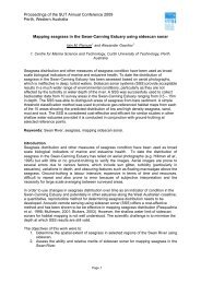
and tested by AME CRC. <strong>The</strong> parent hull <strong>for</strong>m <strong>in</strong> the<br />
AME CRC series, 004a, is an IMS type yacht based on<br />
the Delft Series 2 yacht <strong>for</strong>m. A body plan <strong>of</strong> the yacht<br />
is shown <strong>in</strong> Fig. 1.<br />
Page 75
Fig. 2 Body Plan <strong>of</strong> AMECRC 004a<br />
<strong>The</strong> follow<strong>in</strong>g five hull <strong>for</strong>m parameters were<br />
<strong>in</strong>vestigated <strong>in</strong> calm and rough water:<br />
1. stern overhang length<br />
2. LCF-LCB separation<br />
3. Cp.<br />
4. Length displacement ratio<br />
5. Beam draft ratio<br />
Stern overhang effects on added resistance <strong>in</strong><br />
waves were exam<strong>in</strong>ed by construct<strong>in</strong>g an additional<br />
stern section to be added to AMECRC 004a. <strong>The</strong><br />
section is 1500 mm long (full scale) and simply extends<br />
the l<strong>in</strong>es <strong>in</strong> a straight l<strong>in</strong>e from the exist<strong>in</strong>g transom.<br />
This additional section was attached us<strong>in</strong>g nuts and<br />
bolts, with the jo<strong>in</strong>t faired by modell<strong>in</strong>g plastic<strong>in</strong>e. <strong>The</strong><br />
result<strong>in</strong>g new model with the additional stern section is<br />
named AMECRC 004b.<br />
To exam<strong>in</strong>e the effect <strong>of</strong> LCB-LCF separation<br />
two further models were designed. AMECRC 005 with<br />
the LCB position moved aft, reduc<strong>in</strong>g the LCB-LCF<br />
separation, and AMECRC 006 which had the LCB<br />
position moved <strong>for</strong>ward <strong>in</strong>creas<strong>in</strong>g the LCB-LCF<br />
separation.<br />
<strong>The</strong> effect <strong>of</strong> prismatic variations was<br />
<strong>in</strong>vestigated by design<strong>in</strong>g two new models with<br />
prismatic coefficient (Cp) values greater than and less<br />
than the values <strong>for</strong> AMECRC 004a. <strong>The</strong> two new<br />
models were AMECRC 007 (Cp lower than<br />
AMECRC 004a) and AMECRC 008 (Cp greater than<br />
AMECRC 004a).<br />
Length displacement ratio was varied whilst<br />
ma<strong>in</strong>ta<strong>in</strong><strong>in</strong>g other hull and sail non-dimensional<br />
parameters, details <strong>of</strong> this variation can be found <strong>in</strong><br />
McRae, et al. (1998) p 4. It is important to ma<strong>in</strong>ta<strong>in</strong><br />
sail non-dimensional parameters because changes <strong>in</strong><br />
displacement require changes <strong>in</strong> stability, which <strong>in</strong> turn<br />
effects the amount od drive <strong>for</strong>ces available <strong>for</strong> the<br />
yacht. Two new models were constructed to suit the<br />
two new displacements, models AMECRC 009 and<br />
AMECRC 010.<br />
Beam draft ratio variation was achieved by<br />
vary<strong>in</strong>g the turn <strong>of</strong> the bilge. This approach yielded<br />
models AMECRC 011 and AMECRC 012, which had<br />
constant displacement and right<strong>in</strong>g moment whilst<br />
vary<strong>in</strong>g B/T.<br />
<strong>The</strong> first models tested, models 005 and 006,<br />
<strong>in</strong>cluded a crew weight component. It was<br />
subsequently discovered that this procedure was not<br />
adopted by Delft University researchers. It was<br />
decided to conduct all future AME CRC tests at the<br />
same tested displacement used at Delft, to allow better<br />
comparisons <strong>of</strong> the two standard series.<br />
<strong>The</strong> parameters <strong>of</strong> the yacht hull <strong>for</strong>ms are shown<br />
<strong>in</strong> Table 1, all <strong>for</strong> the full scale prototype <strong>in</strong><br />
measurement trim. <strong>The</strong> parameters used <strong>for</strong> these<br />
models are considered to represent realistic yacht<br />
designs.<br />
Page 76
004a 004b 005 006 007 008<br />
Length O.A. 11.3 m 11.45 m 11.3 m 11.3 m 11.3 m 11.3 m<br />
Length W.L. 10.0 m 10.0 m 10.0 m 10.0 m 10.0 m 10.0 m<br />
Beam W.L. 2.654 m 2.654 m 2.655 m 2.650 m 2.681 m 2.624 m<br />
Draft 0.417 m 0.417 m 0.417 m 0.417 m 0.423 m 0.416 m<br />
Displacement 5100 kg 5100 kg 5280 kg 5280 kg 5100 kg 5100 kg<br />
Prismatic Coeff. 0.535 0.535 0.532 0.534 0.513 0.554<br />
LCB, from bow -5.418 m -5.418 m -5.595 m -5.235 m -5.417 m -5.385 m<br />
LCF, from bow -5.593 m -5.593 m -5.665 m -5.540 m -5.612 m -5.600 m<br />
LCB-LCF 0.180 m 0.180 m 0.07 m 0.305 m 0.200 m 0.210 m<br />
separation<br />
Gyradius 2.25 m 2.25 m 2.25 m 2.25 m 2.25 m 2.25 m<br />
Model Scale 1 : 5 1 : 5 1 : 5 1 : 5 1 : 5 1 : 5<br />
009 010 011 012<br />
Length O.A. 11.3 m 11.3 m 11.3 m 11.3 m<br />
Length W.L. 10.0 m 10.0 m 10.0 m 10.0 m<br />
Beam W.L. 2.498 m 2.785 m 2.622 m 2.669 m<br />
Draft 0.343 m 0.486 m 0.363 m 0.480 m<br />
Displacement 4100 kg 6100 kg 5100 kg 5100 kg<br />
Prismatic Coeff. 0.534 0.535 0.533 0.536<br />
LCB, from bow -5.416 m -5.419 m -5.415 m -5.396 m<br />
LCF, from bow -5.599 m -5.596 m -5.626 m -5.592 m<br />
LCB-LCF 0.180 m 0.180 m 0.180 m 0.200 m<br />
separation<br />
Gyradius 2.25 m 2.25 m 2.25 m 2.25 m<br />
Model Scale 1 : 5 1 : 5 1 : 5 1 : 5<br />
Table 2 AMECRC yacht series parameters, full scale<br />
<strong>The</strong> same keel and rudder were used <strong>for</strong> all<br />
models. In order to stimulate turbulent flow, studs<br />
were attached to the hull at stations 1 and 2 (station<br />
spac<strong>in</strong>g equal to 200 mm). Each stud had a cross<br />
sectional area <strong>of</strong> 8 mm 2 , and they were fitted at a<br />
spac<strong>in</strong>g <strong>of</strong> 25 mm. Studs were also fitted to the keel<br />
and rudder at one third <strong>of</strong> the chord from the lead<strong>in</strong>g<br />
edge. <strong>The</strong>se studs had a cross sectional area <strong>of</strong> 2 mm 2 ,<br />
and they were fitted at a spac<strong>in</strong>g <strong>of</strong> 15 mm.<br />
EXPERIMENTAL PROGRAM<br />
Experimental Setup<br />
<strong>The</strong> experiments were carried out <strong>in</strong> the AME<br />
CRC tow<strong>in</strong>g tank based <strong>in</strong> the Australian Maritime<br />
College, Launceston, Tasmania. <strong>The</strong> tank has a<br />
constant rectangular cross section with the pr<strong>in</strong>cipal<br />
dimensions shown <strong>in</strong> Table 3.<br />
Overall Length 60 m<br />
Width 3.5 m<br />
Depth 1.5 m<br />
Table 4 Test tank parameters<br />
Situated at one end <strong>of</strong> the tank is a s<strong>in</strong>gle flap, flat<br />
plate, hydraulically driven wavemaker. At the other<br />
end is a wet dock used <strong>for</strong> ballast<strong>in</strong>g models.<br />
A steel carriage runn<strong>in</strong>g on rails along the walls<br />
<strong>of</strong> the tank, with a maximum speed <strong>of</strong> 4.5 m/s, is used<br />
to tow the models.<br />
<strong>The</strong> model was connected to the carriage us<strong>in</strong>g a<br />
s<strong>in</strong>gle post yacht dynamometer, and was free to pitch<br />
and heave, but constra<strong>in</strong>ed <strong>in</strong> surge, sway, yaw and<br />
roll. <strong>The</strong> dynamometer comprises: two flexures<br />
arranged orthogonally to enable lift and drag<br />
measurements; a torsion cell <strong>for</strong> measur<strong>in</strong>g yaw<br />
moment; a stra<strong>in</strong> gauge <strong>for</strong> measur<strong>in</strong>g roll moment; a<br />
rotary potentiometer <strong>for</strong> determ<strong>in</strong><strong>in</strong>g pitch and a l<strong>in</strong>ear<br />
potentiometer <strong>for</strong> measur<strong>in</strong>g heave. This dynamometer<br />
is identical to that used by the Wolfson unit used at<br />
Southampton University <strong>in</strong> the UK.<br />
In order to measure the wave height and also<br />
determ<strong>in</strong>e the motion phase relationships, a capacitance<br />
wave probe was fixed to the carriage, clear <strong>of</strong> any wave<br />
disturbance from the model.<br />
Page 77
<strong>The</strong> data from the dynamometer and wave probe<br />
were processed us<strong>in</strong>g an analog to digital converter and<br />
then recorded by an IBM-PC mounted on the carriage,<br />
record<strong>in</strong>g at a rate <strong>of</strong> 20 Hz.<br />
Model Ballast<strong>in</strong>g<br />
Each model was ballasted to its required<br />
displacement and trim. This weight was then<br />
distributed along the model to achieve a full scale<br />
gyradius <strong>of</strong> 2.25 m about the LCB. <strong>The</strong> bifilar method,<br />
which assumes that the pitch gyradius is equal to the<br />
yaw gyradius, was used <strong>for</strong> estimat<strong>in</strong>g the pitch radius<br />
<strong>of</strong> gyration.<br />
S<strong>in</strong>ce the tank tests were conducted with the<br />
models at constra<strong>in</strong>ed angles <strong>of</strong> heel and yaw, weights<br />
were shifted laterally to heel the model to the required<br />
angle, thus m<strong>in</strong>imis<strong>in</strong>g the stress on the dynamometer.<br />
<strong>The</strong> models were additionally ballasted to account <strong>for</strong><br />
the pitch moment and vertical <strong>for</strong>ce applied by the<br />
sails.<br />
6000<br />
5000<br />
4000<br />
3000<br />
2000<br />
1000<br />
Experimental Conditions<br />
For each model a complete set <strong>of</strong> calm water<br />
resistance tests were conducted, between the speeds<br />
4.5 knots and 11.0 knots (full scale), at vary<strong>in</strong>g angles<br />
<strong>of</strong> heel and yaw. <strong>The</strong> heel angles tested were 0°, 10°,<br />
20° and 25° degrees, whilst the yaw angles were 0°, 3°<br />
and 5°. Such a comprehensive set <strong>of</strong> calm water tests<br />
is required to establish a VPP resistance matrix.<br />
All the rough water tests were conducted at the<br />
design w<strong>in</strong>dward speed <strong>of</strong> 6.5 knots (full scale) <strong>in</strong><br />
regular head seas. <strong>The</strong> models were constra<strong>in</strong>ed at a<br />
heel angle <strong>of</strong> 20° and a yaw angle <strong>of</strong> 3° (the rudder<br />
angle relative to the yacht centrel<strong>in</strong>e was set to the<br />
same as the yaw angle). <strong>The</strong> tests were carried out <strong>for</strong><br />
a range <strong>of</strong> wave periods between 2.0 s and 5.0 s (full<br />
scale), at a constant wave slope.<br />
Repeat Experiments<br />
For each wave height and frequency three runs<br />
were conducted to <strong>in</strong>crease the test data recorded and<br />
provide a check on repeatability. An example <strong>of</strong> the<br />
spread <strong>of</strong> the added resistance RAO between these<br />
three runs can be seen <strong>in</strong> Fig. 3.<br />
0<br />
1.5 2 2.5 3 3.5 4 4.5 5 5.5<br />
Fig. 4 Example <strong>of</strong> repeated test <strong>for</strong> model 004a<br />
CALM WATER EXPERIMENTS<br />
A full calm water matrix <strong>of</strong> test runs was<br />
completed <strong>for</strong> each <strong>of</strong> the models, this allowed the<br />
Incident Wave Period (s), Full Scale<br />
S<strong>in</strong>gle experiments, 004a, Experimental<br />
Averaged results, 004a Experimental<br />
results to be used <strong>in</strong> a velocity prediction program. An<br />
example <strong>of</strong> such results and their uses have been<br />
detailed <strong>in</strong> McRae et al. (1998). An example <strong>of</strong> the<br />
calm water resistance is shown <strong>in</strong> Fig. 5.<br />
Page 78
0.3<br />
0.28<br />
0.26<br />
0.24<br />
0.22<br />
0.2<br />
0.18<br />
0.16<br />
0.14<br />
0.12<br />
004<br />
009<br />
010<br />
0.1<br />
2.5 2.7 2.9 3.1 3.3 3.5 3.7 3.9 4.1 4.3<br />
V (m/s)<br />
Fig. 6 Calm water Cts vs full scale speed, <strong>for</strong> 20° heel, 3° yaw<br />
In Fig. 7 the total resistance coefficient was calculated<br />
us<strong>in</strong>g a full scale reference area <strong>of</strong> 1 m 2 and a <strong>for</strong>m<br />
factor <strong>of</strong> zero.<br />
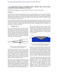
THEORETICAL PREDICTIONS<br />
A computer program that predicts the motions,<br />
loads and added resistance experienced by vessels <strong>in</strong> a<br />
seaway has been developed by AMECRC (Sutherland,<br />
1987). It is based upon strip theory (see Salvesen,<br />
Tuck and Falt<strong>in</strong>sen, 1970), where the yacht is divided<br />
<strong>in</strong>to a series <strong>of</strong> transverse strips. <strong>The</strong> yacht is modelled<br />
as a two degrees <strong>of</strong> freedom spr<strong>in</strong>g, mass and damper<br />
system undergo<strong>in</strong>g s<strong>in</strong>usoidal motion due to an excit<strong>in</strong>g<br />
<strong>for</strong>ce from regular waves. <strong>The</strong> method proposed by<br />
Gerritsma and Beukelman (Gerritsma and Beukelman,<br />
1972) is used to calculate the added resistance <strong>of</strong> the<br />
yacht.<br />
Certa<strong>in</strong> non-l<strong>in</strong>ear effects have subsequently been<br />
<strong>in</strong>corporated <strong>in</strong>to this program 'SEALAM' (Boyd,<br />
Klaka and Thomas, 1995). <strong>The</strong> hydrodynamic<br />
coefficients are calculated from the true 'local<br />
waterl<strong>in</strong>e' position along the hull rather than assum<strong>in</strong>g a<br />
cont<strong>in</strong>uous flat waterl<strong>in</strong>e as <strong>in</strong> conventional strip theory<br />
programs. Effects such as the Kelv<strong>in</strong> wave pattern,<br />
immersion and emergence <strong>of</strong> bow and stern sections,<br />
the pr<strong>of</strong>ile <strong>of</strong> the <strong>in</strong>cident wave and the amplitude and<br />
phas<strong>in</strong>g <strong>of</strong> the resultant motions are there<strong>for</strong>e<br />
considered.<br />
SEALAM was used to <strong>in</strong>vestigate the <strong>in</strong>fluence <strong>of</strong><br />
hull <strong>for</strong>m parameters on yacht motions and added<br />
resistance <strong>in</strong> waves.<br />
EXPERIMENTAL AND THEORETICAL<br />
RESULTS<br />
Stern Overhang<br />
<strong>The</strong> added resistance RAOs <strong>for</strong> the two models<br />
used to test stern overhang are shown <strong>in</strong>. Fig. 8 <strong>for</strong> both<br />
experimental and theoretical predictions.<br />
Page 79
7000<br />
6000<br />
5000<br />
4000<br />
3000<br />
2000<br />
1000<br />
0<br />
1.5 2 2.5 3 3.5 4 4.5 5<br />
Incident Wave Period (s), Full Scale<br />
Fig. 9 Added resistance RAO <strong>for</strong> stern overhang <strong>in</strong>vestigation<br />
LCB-LCF Separation<br />
<strong>The</strong> added resistance RAOs <strong>for</strong> the three models<br />
used to test LCB-LCF separation are shown <strong>in</strong> Fig. 10.<br />
7000<br />
6000<br />
5000<br />
4000<br />
3000<br />
2000<br />
1000<br />
0<br />
004a, Experimental<br />
004b, Experimental<br />
004a, <strong>The</strong>oretical<br />
004b, <strong>The</strong>oretical<br />
1.5 2 2.5 3 3.5 4 4.5 5<br />
Incident Wave Period (s), Full Scale<br />
Fig. 11 Added resistance RAO <strong>for</strong> LCB-LCF separation <strong>in</strong>vestigation<br />
Prismatic Coefficient<br />
<strong>The</strong> added resistance RAOs <strong>for</strong> the three models<br />
used to test the effects <strong>of</strong> test prismatic coefficient on<br />
added resistance are shown <strong>in</strong> Fig. 12.<br />
004a, Experimental<br />
005, Experimental<br />
006, Experimental<br />
005, <strong>The</strong>oretical<br />
006, <strong>The</strong>oretical<br />
004, <strong>The</strong>oretical<br />
Page 80
7000<br />
6000<br />
5000<br />
4000<br />
3000<br />
2000<br />
1000<br />
0<br />
1.5 2 2.5 3 3.5 4 4.5 5<br />
Incident Wave Period (s), Full Scale<br />
Fig. 13 Added resistance RAO <strong>for</strong> prismatic coefficient <strong>in</strong>vestigation<br />
Displacement Length Ratio<br />
<strong>The</strong> added resistance RAO <strong>for</strong> the three models<br />
used to test the affects <strong>of</strong> displacement length ratio on<br />
added resistance are shown <strong>in</strong> Fig. 14.<br />
7000<br />
6000<br />
5000<br />
4000<br />
3000<br />
2000<br />
1000<br />
0<br />
004 Experimental<br />
007 Experimental<br />
008 Experimental<br />
004 <strong>The</strong>oretical<br />
007 <strong>The</strong>oretical<br />
008 <strong>The</strong>oretical<br />
1.5 2 2.5 3 3.5 4 4.5 5<br />
Incident Wave Period (s), Full Scale<br />
Fig. 15 Added resistance RAO <strong>for</strong> displacement length ratio <strong>in</strong>vestigation<br />
Beam Draft Ratio<br />
<strong>The</strong> added resistance RAOs <strong>for</strong> the three models<br />
used to test the effects <strong>of</strong> beam draft ratio on added<br />
resistance are shown <strong>in</strong> Fig. 16.<br />
004, Experimental<br />
009, Experimental<br />
010, Experimental<br />
004, <strong>The</strong>oretical<br />
009, <strong>The</strong>oretical<br />
010, <strong>The</strong>oretical<br />
Page 81
7000.0<br />
6000.0<br />
5000.0<br />
4000.0<br />
3000.0<br />
2000.0<br />
1000.0<br />
0.0<br />
1.5 2 2.5 3 3.5 4 4.5 5<br />
Incident Wave Period (s), Full Scale<br />
Fig. 17 Added resistance RAO <strong>for</strong> beam draft ratio <strong>in</strong>vestigation<br />
DISCUSSION OF RESULTS<br />
Stern Overhang<br />
<strong>The</strong> effect <strong>of</strong> the stern overhang extension was<br />
quite small on the added resistance. Fig. 18 shows that<br />
these affects appear to vary with frequency. <strong>The</strong><br />
theoretical predictions also show a dependence on<br />
frequency, however, the predictions and the<br />
experiments do not agree <strong>in</strong> the nature <strong>of</strong> the variation<br />
with frequency. <strong>The</strong> effect <strong>of</strong> overhang on the<br />
predicted results is a highly non-l<strong>in</strong>ear one. This was<br />
also concluded <strong>in</strong> previous research, <strong>for</strong> example Kuhn<br />
and Schlageter, 1993, p 261. In the research by Kuhn<br />
and Schlageter the predictions followed the same trends<br />
as those presented <strong>in</strong> Fig. 19. It is believed that the<br />
non-l<strong>in</strong>earities present <strong>in</strong> these test conditions have not<br />
been modelled correctly <strong>in</strong> the SEALAM predictions.<br />
LCB-LCF Separation<br />
<strong>The</strong> effect <strong>of</strong> centroid separation would appear to<br />
be heavily dependant on wave period, as shown by<br />
Fig. 20 . <strong>The</strong>re<strong>for</strong>e the effect on per<strong>for</strong>mance depends<br />
on the wave spectrum encountered. This is a somewhat<br />
different conclusion to that <strong>of</strong> Sclavounos and Nakos,<br />
1993, <strong>in</strong> which it was calculated that added resistance<br />
was reduced <strong>for</strong> LCF mov<strong>in</strong>g aft, and <strong>in</strong>creased <strong>for</strong><br />
LCB mov<strong>in</strong>g aft. One possible reason <strong>for</strong> the trends<br />
not be<strong>in</strong>g as clearly def<strong>in</strong>ed across the frequency<br />
spectrum <strong>in</strong> the results presented here is that the models<br />
used <strong>in</strong> this research were 53% lighter than the models<br />
used <strong>in</strong> Sclavounos. It is there<strong>for</strong>e likely that this<br />
004, Experimental<br />
011, Experimental<br />
012, Experimental<br />
004, <strong>The</strong>oretical<br />
011, <strong>The</strong>oretical<br />
012, <strong>The</strong>oretical<br />
difference <strong>in</strong> displacement is the dom<strong>in</strong>at<strong>in</strong>g parameter<br />
<strong>in</strong> compar<strong>in</strong>g these results to those obta<strong>in</strong>ed by<br />
Sclavounos.<br />
Prismatic Coefficient<br />
<strong>The</strong> effect <strong>of</strong> CP on the RAO <strong>of</strong> the added<br />
resistance is small <strong>in</strong> comparison with other parameters<br />
<strong>in</strong>vestigated. In Fig. 21 this is shown <strong>in</strong> both the<br />
experimental results and the theoretical predictions.<br />
This conclusion is generally not suppported by<br />
experience on the race course, which tends to suggest<br />
that a yacht with a large CP will not per<strong>for</strong>m well.<br />
Differences suggest<strong>in</strong>g this conclusion can be drawn<br />
when results are processed us<strong>in</strong>g the VPP and utilis<strong>in</strong>g<br />
a fully developed sea-state, which will tend to bias the<br />
higher period wave per<strong>for</strong>mance, <strong>for</strong> which there is a<br />
very slight advantage to the smaller CP yacht.<br />
Length Displacement Ratio<br />
<strong>The</strong> effect <strong>of</strong> length displacement ratio is quite<br />
clear <strong>for</strong> both theory and prediction, that is an <strong>in</strong>crease<br />
<strong>in</strong> length displacement ratio will result <strong>in</strong> an <strong>in</strong>crease <strong>in</strong><br />
added resistance <strong>in</strong> head seas. However, a shift <strong>in</strong> the<br />
cross over po<strong>in</strong>t and the resonant frequency could<br />
result <strong>in</strong> slightly different answers be<strong>in</strong>g calculated if<br />
theoretical predictions were used to replace<br />
experimental results. This situation arises when sea<br />
spectra with resonant frequencies located around yacht<br />
resonant frequencies are used. <strong>The</strong>re<strong>for</strong>e when us<strong>in</strong>g<br />
these results <strong>for</strong> per<strong>for</strong>mance predictions consideration<br />
should be given to this fact by conduct<strong>in</strong>g sensitivity<br />
studies on the sea spectra used.<br />
Page 82
Beam Draft Ratio<br />
<strong>The</strong> trends predicted by theory and experment <strong>in</strong><br />
this case vary considerably <strong>in</strong> magnitude and direction.<br />
From the experimental results it can be seen that yachts<br />
with a low to moderate B/T (models 004 and 012) are<br />
reasonably equal <strong>in</strong> terms <strong>of</strong> added resistance <strong>in</strong> waves.<br />
<strong>The</strong> experiments also show fairly clearly that a high<br />
B/T yacht (model 011) exhibits a very poor<br />
per<strong>for</strong>mance <strong>in</strong> waves, with a considerable <strong>in</strong>crease <strong>in</strong><br />
added resistance <strong>in</strong> waves.<br />
<strong>The</strong> theoretical predictions show quite a different<br />
story however. It would appear that all yachts are<br />
extremely close <strong>in</strong> terms <strong>of</strong> added resistance <strong>in</strong> waves,<br />
however a small trend show<strong>in</strong>g a small B/T ratio to<br />
per<strong>for</strong>m worse <strong>in</strong> waves can be seen from the<br />
theoretical predictions.<br />
<strong>The</strong> differences between theory and experiment<br />
here are thought to be due to the bias placed by theory<br />
on the characteristics <strong>of</strong> the water plane. <strong>The</strong>se three<br />
yachts have almost identical water planes, and so<br />
theory cannot discenr the difference at all well.<br />
However, the underwater sectional shapes <strong>of</strong> these<br />
yachts vary considerably and so the experimental<br />
results vary accord<strong>in</strong>gly.<br />
INTEGRATION OF RESULTS INTO THE AME<br />
VPP<br />
Given the results above and a sea spectrum it is<br />
possible to calculate an average added resistance <strong>for</strong><br />
that sea condtion.<br />
Sea Spectrum Def<strong>in</strong>ition<br />
Firstly, the problem is simplified by assum<strong>in</strong>g the<br />
sea state is long crested, that is it has no spread<strong>in</strong>g<br />
function. Secondly a relationship between w<strong>in</strong>d speed<br />
and wave spectra needs to be decided upon. This may<br />
be done by us<strong>in</strong>g a sea spectrum which is dependant on<br />
w<strong>in</strong>d speed, such as the Pierson-Moskowitz, or by<br />
us<strong>in</strong>g wave data gathered simultaneuously with w<strong>in</strong>d<br />
data. Next a relationship between w<strong>in</strong>d direction and<br />
wave direction needs to be determ<strong>in</strong>ed, <strong>for</strong> all <strong>of</strong> the<br />
studies conducted dur<strong>in</strong>g this project the w<strong>in</strong>d direction<br />
was assumed to equal the wave direction.<br />
F<strong>in</strong>ally a relato<strong>in</strong>ship between wave frequency<br />
and wave amplitude energy density needs to be<br />
calculated. Aga<strong>in</strong> this may be done by either us<strong>in</strong>g a<br />
standard wave spectrum def<strong>in</strong>ition or by us<strong>in</strong>g actual<br />
wave data. If actual wave data is used a Fourier<br />
trans<strong>for</strong>m can be per<strong>for</strong>med on the time series to<br />
produce an actual wave spectrum.<br />
Modification to RAOs<br />
<strong>The</strong> experimental and theoretical RAOs <strong>for</strong> added<br />
resistance <strong>in</strong> waves are <strong>for</strong> head seas cases, however<br />
sail<strong>in</strong>g yachts rarely encounter head seas. <strong>The</strong><br />
restrictions imposed by assumptions made <strong>in</strong> the<br />
theoretical predictions and by tank dimensions <strong>in</strong> the<br />
experimental results have precluded this project from<br />
mak<strong>in</strong>g an accurate assessment as to the exact nature <strong>of</strong><br />
this variation. <strong>The</strong>re<strong>for</strong>e the problem was simplified<br />
greatly by assum<strong>in</strong>g that the added resistance <strong>for</strong> a head<br />
seas case would be a maximum and it would be zero<br />
<strong>for</strong> a beam seas case, all angles <strong>in</strong> between have been<br />
calculated by a simple l<strong>in</strong>ear <strong>in</strong>terpolation.<br />
Calculation <strong>of</strong> Average Added Resistance<br />
<strong>The</strong> average added resistance <strong>of</strong> a yacht may be<br />
calculated from Equation (1), given below<br />
∞<br />
∫ . (1)<br />
Raw = 2 RAO Se(ωe)dωe<br />
0<br />
In Equation (2) RAO is the response amplitude<br />
operator, ωe is the encounter frequency and Se(ωe) is<br />
the wave energy specturm.<br />
CONCLUSIONS<br />
Test tank results <strong>for</strong> a heeled, yawed yacht and<br />
theoretical predictions <strong>for</strong> an upright, zero-leeway<br />
yacht <strong>in</strong> regular seas are presented.<br />
A non-l<strong>in</strong>ear strip theory code has provided<br />
valuable results on the effect <strong>of</strong> above- and belowwaterl<strong>in</strong>e<br />
hull variations on added resistance. Although<br />
the trends around the peak <strong>of</strong> the added resistance have<br />
not been well predicted, the trends toward the higher<br />
wave periods are well predicted.<br />
<strong>The</strong> effect <strong>of</strong> stern overhang is large with respect<br />
to the other parameters <strong>in</strong>vestigated and would appear<br />
to depend on the <strong>in</strong>cident wave period, <strong>in</strong> an <strong>in</strong>herently<br />
non-l<strong>in</strong>ear manner.<br />
<strong>The</strong> effect <strong>of</strong> LCB-LCF separation on added<br />
resistance is dependant on wave period. <strong>The</strong>se effects<br />
have not mirrored the results <strong>of</strong> previous research,<br />
however the displacement used <strong>in</strong> this series <strong>of</strong><br />
experiments was substantially less than that used <strong>in</strong><br />
previous research.<br />
<strong>The</strong> effect <strong>of</strong> <strong>of</strong> the change <strong>in</strong> CP <strong>in</strong>vestigated is<br />
small <strong>in</strong> comparison with the other parameters.<br />
<strong>The</strong> effects <strong>of</strong> displacement to length ratio are<br />
shown to be large, and extremely well predicted by<br />
theory.<br />
<strong>The</strong> effects <strong>of</strong> beam draft ratio have been very<br />
badly predicted by theory, and perhaps demonstrate a<br />
case where theory should not be used at all.<br />
Page 83
ACKNOWLEDGMENTS<br />
<strong>The</strong> authors wish to acknowledge the assistance<br />
<strong>of</strong> the Australian Maritime Eng<strong>in</strong>eer<strong>in</strong>g CRC Ltd. <strong>in</strong><br />
provid<strong>in</strong>g support and fund<strong>in</strong>g <strong>for</strong> the research<br />
presented <strong>in</strong> this paper.<br />
<strong>The</strong> authors would also like to thank the staff <strong>of</strong><br />
the Australian Maritime College, Launceston, <strong>for</strong> their<br />
help dur<strong>in</strong>g experiments..<br />
REFERENCES<br />
Boyd, J., Klaka, K. and Thomas, G., “Analysis <strong>of</strong> Non-<br />
L<strong>in</strong>ear Motions: Experiments and Predictions”, RINA<br />
Intl. Conf. Seakeep<strong>in</strong>g and Weather, London, 1995<br />
Couser, P., “Prediction <strong>of</strong> Aerodynamic Sail Forces <strong>for</strong><br />
Upw<strong>in</strong>d Yacht Velocity Prediction Programs”, 1st<br />
Australian Sail<strong>in</strong>g Science Conference, 1997<br />
Gerritsma, J. and Beukelman, W., “Analysis <strong>of</strong> the<br />
Resistance Increase <strong>in</strong> Waves <strong>of</strong> a Fast Cargo Ship”,<br />
International Shipbuild<strong>in</strong>g Progress, 1972<br />
Gerritsma, J., Keun<strong>in</strong>g, J.A., and Versluis, A., “Sail<strong>in</strong>g<br />
Yacht <strong>Per<strong>for</strong>mance</strong> <strong>in</strong> Calm <strong>Water</strong> and Waves”, <strong>The</strong><br />
11th Chesapeake Sail<strong>in</strong>g Yacht Symposium, 1993,<br />
pp 233-245<br />
Kuhn, J.C. and Schlageter, E.C., “<strong>The</strong> Effects <strong>of</strong> Flare<br />
and Overhang on the Motions <strong>of</strong> a Yacht <strong>in</strong> Head<br />
Seas”, 11th Chesapeake Sail<strong>in</strong>g Yacht Symposium,<br />
1993, pp 261-276<br />
McRae, B., B<strong>in</strong>ns, J.R., Klaka, K. and Dovell, A.,<br />
“<strong>W<strong>in</strong>dward</strong> <strong>Per<strong>for</strong>mance</strong> <strong>of</strong> the AMECRC Systematic<br />
Yacht Series”, International Conference on the<br />
Modern Yacht, 1998<br />
Salvesen, N., Tuck, E.O. and Falt<strong>in</strong>sen, O., “Ship<br />
Motions and Sea Loads”, Transactions SNAME, 1970<br />
Sclavounos, P.D., and Nakos, D.E., “Seakeep<strong>in</strong>g and<br />
Added Resistance <strong>of</strong> IACC <strong>Yachts</strong> by a Three-<br />
Dimensional Panel Method”, 11th Chesapeake Sail<strong>in</strong>g<br />
Yacht Symposium, 1993, pp 247-260<br />
Sutherland, I.W., Prediction <strong>of</strong> Hull Responses to<br />
Waves, MAppSc <strong>The</strong>sis, Curt<strong>in</strong> University <strong>of</strong><br />
Technology, 1987<br />
Thomas, G., Klaka, K. and Dovell, A., “Project 1.5.2<br />
Development <strong>of</strong> a Velocity Prediction Program <strong>for</strong><br />
Yacht <strong>W<strong>in</strong>dward</strong> <strong>Per<strong>for</strong>mance</strong> <strong>in</strong> Waves, Report 1”,<br />
AMECRC IR 95/8, 1995<br />
Thomas, G., Klaka, K. and Dovell, A., “<strong>The</strong> Effect <strong>of</strong><br />
Stern Overhangs on the Added Resistance <strong>of</strong> <strong>Yachts</strong> <strong>in</strong><br />
Waves”, AMECRC IR 95/16, 1995<br />
Page 84