The compatibility of LCD TVs with time-sequential stereoscopic 3D ...
The compatibility of LCD TVs with time-sequential stereoscopic 3D ...
The compatibility of LCD TVs with time-sequential stereoscopic 3D ...

Create successful ePaper yourself
Turn your PDF publications into a flip-book with our unique Google optimized e-Paper software.
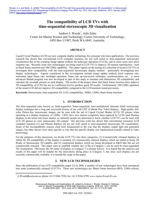
Woods, A.J, and Sehic, A. (2009) “<strong>The</strong> <strong>compatibility</strong> <strong>of</strong> <strong>LCD</strong> <strong>TVs</strong> <strong>with</strong> <strong>time</strong>-<strong>sequential</strong> <strong>stereoscopic</strong> <strong>3D</strong> visualization” in Stereoscopic<br />
Displays and Applications XX, Proceedings <strong>of</strong> Electronic Imaging, Proc SPIE Vol. 7237, San Jose, California, 19-21 January 2009.<br />
Online: http://www.AndrewWoods<strong>3D</strong>.com<br />
<strong>The</strong> <strong>compatibility</strong> <strong>of</strong> <strong>LCD</strong> <strong>TVs</strong> <strong>with</strong><br />
<strong>time</strong>-<strong>sequential</strong> <strong>stereoscopic</strong> <strong>3D</strong> visualization<br />
Andrew J. Woods * , Adin Sehic<br />
Centre for Marine Science and Technology, Curtin University <strong>of</strong> Technology,<br />
GPO Box U1987, Perth WA 6845, Australia.<br />
ABSTRACT<br />
Liquid Crystal Displays (<strong>LCD</strong>) are now a popular display technology for consumer television applications. Our previous<br />
research has shown that conventional <strong>LCD</strong> computer monitors are not well suited to <strong>time</strong>-<strong>sequential</strong> <strong>stereoscopic</strong><br />
visualization due to the scanning image update method, the hold-type operation <strong>of</strong> <strong>LCD</strong>s, and in some cases slow pixel<br />
response rate. Recently some new technologies are being used in <strong>LCD</strong> <strong>TVs</strong> to improve 2D motion reproduction - such<br />
as black frame insertion and 100/120Hz capability. This paper reports on the testing <strong>of</strong> a selection <strong>of</strong> recent <strong>LCD</strong> <strong>TVs</strong> to<br />
investigate their <strong>compatibility</strong> <strong>with</strong> the <strong>time</strong>-<strong>sequential</strong> <strong>stereoscopic</strong> display method – particularly investigating new<br />
display technologies. Aspects considered in this investigation include image update method, pixel response rate,<br />
maximum input frame rate, backlight operation, frame rate up-conversion technique, synchronization, etc. A more<br />
advanced Matlab program was also developed as part <strong>of</strong> this study to simulate and characterize <strong>3D</strong> <strong>compatibility</strong> and<br />
calculate the crosstalk present on each display. <strong>The</strong> results <strong>of</strong> the project show that black frame insertion does improve<br />
<strong>3D</strong> <strong>compatibility</strong> <strong>of</strong> <strong>LCD</strong>s but not to a sufficient level to produce good <strong>3D</strong> results. Unfortunately 100/120Hz operation<br />
<strong>of</strong> the tested <strong>LCD</strong> did not improve <strong>3D</strong> <strong>compatibility</strong> compared to the <strong>LCD</strong> monitors tested previously.<br />
Keywords: Stereoscopic, <strong>time</strong>-<strong>sequential</strong> <strong>3D</strong>, <strong>LCD</strong>, <strong>compatibility</strong>, 100Hz, 120Hz, black frame insertion.<br />
1. INTRODUCTION<br />
<strong>The</strong> <strong>time</strong>-<strong>sequential</strong> (also known as: field-<strong>sequential</strong>, frame-<strong>sequential</strong>, <strong>time</strong>-multiplexed, alternate field) <strong>stereoscopic</strong><br />
display technique has a long and successful history <strong>of</strong> use <strong>with</strong> CRT (Cathode Ray Tube) displays. High-quality fullcolor<br />
flicker-free <strong>stereoscopic</strong> images can be seen <strong>with</strong> the aid <strong>of</strong> Liquid Crystal Shutter (LCS) <strong>3D</strong> glasses when<br />
operating at a display frequency <strong>of</strong> 120Hz. CRTs have now almost completely been replaced by <strong>LCD</strong>s (and Plasma)<br />
displays in the home television market, so naturally people are interested to know whether <strong>LCD</strong> <strong>TVs</strong> can be used <strong>with</strong><br />
LCS <strong>3D</strong> glasses to view <strong>stereoscopic</strong> <strong>3D</strong> content. Our previous work has shown that conventional consumer <strong>LCD</strong><br />
computer monitors [1] and Plasma displays [2] are not well suited to <strong>time</strong>-<strong>sequential</strong> <strong>stereoscopic</strong> <strong>3D</strong> visualization.<br />
Some <strong>of</strong> the in<strong>compatibility</strong> reasons cited were fundamental to the way that the displays output light and generated<br />
images, but other factors were more specific to way that the specific display was implemented (usually related to video<br />
processing).<br />
For the purposes <strong>of</strong> this discussion, we divide <strong>LCD</strong> <strong>TVs</strong> into three categories: (1) Commercially released displays in<br />
which the <strong>3D</strong> <strong>compatibility</strong> <strong>of</strong> the display is unstated, (2) commercially released displays which are stated as being <strong>3D</strong><br />
Ready or Stereoscopic <strong>3D</strong> capable, and (3) customized displays which are being developed in R&D labs but are not<br />
commercially released. This paper aims to establish whether any <strong>LCD</strong>s in Category 1 can be used for <strong>time</strong>-<strong>sequential</strong><br />
<strong>3D</strong> visualization. Obviously the <strong>3D</strong> status <strong>of</strong> displays in Category 2 is already known. It is hoped that the analyses and<br />
results <strong>of</strong> this paper will be helpful for the innovations taking place in Category 3, but since such displays are not<br />
currently commercially available, it is outside the scope <strong>of</strong> this paper.<br />
2. NEW <strong>LCD</strong> TECHNOLOGIES<br />
Since the publication <strong>of</strong> our <strong>LCD</strong> <strong>compatibility</strong> paper [1] in 2006, a number <strong>of</strong> new technologies have been introduced<br />
into some commercially released <strong>LCD</strong> <strong>TVs</strong>. <strong>The</strong>se new technologies are: Black Frame Insertion (BFI), 120Hz refresh,<br />
* A.Woods curtin.edu.au; phone +61 8 9266 7920; fax +61 8 9266 4799; www.AndrewWoods<strong>3D</strong>.com<br />
Stereoscopic Displays and Applications XX, edited by Andrew J. Woods, Nicolas S. Holliman,<br />
John O. Merritt, Proceedings <strong>of</strong> SPIE-IS&T Electronic Imaging, SPIE Vol. 7237, 72370N<br />
© 2009 SPIE-IS&T · CCC code: 0277-786X/09/$18 · doi: 10.1117/12.811838<br />
SPIE-IS&T/ Vol. 7237 72370N-1
and modulated backlight. <strong>The</strong>se technologies have been introduced to improve the reproduction <strong>of</strong> moving images in 2D<br />
viewing (nothing to do <strong>with</strong> <strong>3D</strong> viewing). Conventional <strong>LCD</strong>s suffer from a problem called image smear (<strong>of</strong>ten known<br />
as motion blur) which is caused by <strong>LCD</strong>s being a hold-type display [3]. <strong>The</strong>se new technologies reduce the presence <strong>of</strong><br />
image smear, but this paper considers how these technologies affect <strong>time</strong>-<strong>sequential</strong> <strong>3D</strong> <strong>compatibility</strong>.<br />
2.1 Black Frame Insertion (BFI)<br />
Black Frame Insertion can be considered two ways, either (a) the display <strong>time</strong> <strong>of</strong> each individual frame is reduced and<br />
replaced <strong>with</strong> black, in effect reducing the duty cycle <strong>of</strong> each frame, or (b) the display adds a black frame between each<br />
original video input frame. Image smear will be reduced because the hold-<strong>time</strong> is reduced, however one problem <strong>with</strong><br />
this technique is that if the backlight brightness isn’t increased, the brightness <strong>of</strong> the display will be reduced in<br />
proportion to the amount <strong>of</strong> BFI introduced. It could be argued that the insertion <strong>of</strong> the intermediate black frames<br />
increases the display frequency up to 120Hz, but these extra frames are just black, not new image frames, so it is still 60<br />
frames per second, but <strong>with</strong> a reduced on <strong>time</strong> per frame. BFI is some<strong>time</strong>s compared to the modulated backlight<br />
technology, and although the effect on image smear is similar, BFI is different because it is implemented at the <strong>LCD</strong><br />
panel, not the backlight.<br />
2.2 120Hz Refresh<br />
This technology works by interpolating extra frames between the original 60Hz frames provided at the video signal<br />
input. <strong>The</strong> 60 original frames per second plus the new interpolated frames interspersed between the original frames<br />
results in 120 frames per second (120Hz). At the new 120Hz image rate, the <strong>time</strong> on screen per frame is halved, and<br />
hence the integration <strong>time</strong> is halved which in turn reduces image smear for moving objects. With 60Hz input sources the<br />
display rate is doubled to 120Hz, and for 50Hz input sources the display rate is doubled to 100Hz.<br />
2.3 Modulated Backlight<br />
Also known as strobing backlight or scanning backlight, in this case image smear is reduced because the on-<strong>time</strong> <strong>of</strong> each<br />
frame is reduced by switching the backlight on and <strong>of</strong>f (reducing the duty cycle). With a strobing backlight the entire<br />
backlight is turned on and <strong>of</strong>f all at once. With a scanning backlight the on and <strong>of</strong>f cycle is scanned down the display in<br />
segments, usually following the scan-like image update <strong>of</strong> the <strong>LCD</strong>.<br />
3. IMPORTANT <strong>LCD</strong> AND LCS PROPERTIES<br />
Our work in 2006 [1] identified several important properties <strong>of</strong> <strong>LCD</strong> monitors and LCS <strong>3D</strong> glasses which determine the<br />
<strong>compatibility</strong> <strong>of</strong> a particular display <strong>with</strong> the <strong>time</strong>-<strong>sequential</strong> <strong>stereoscopic</strong> <strong>3D</strong> display method.<br />
3.1 <strong>LCD</strong> and LCS Native Polarization<br />
<strong>The</strong> <strong>LCD</strong> and the LCS both have a native (linear) polarization angle – if these are orthogonal, the display will appear<br />
black when viewed through the LCS glasses. This is easily overcome by the use <strong>of</strong> a quarter or half-wave retarder, or<br />
designing the LCS <strong>with</strong> a different polarization orientation.<br />
3.2 Refresh Rate<br />
<strong>The</strong> maximum refresh rate <strong>of</strong> a monitor determines the maximum speed at which it can display a sequence <strong>of</strong> images. A<br />
refresh rate <strong>of</strong> 100-120Hz is usually considered necessary for flicker-free viewing <strong>with</strong> the <strong>time</strong>-<strong>sequential</strong> <strong>3D</strong> method.<br />
<strong>The</strong> maximum refresh rate which can be used successfully for <strong>time</strong>-<strong>sequential</strong> <strong>3D</strong> is determined by two factors: (a) the<br />
maximum rate at which the input electronic will accept a video signal, and (b) the maximum rate at which the internal<br />
display electronics will drive the <strong>LCD</strong> panel. Generally, the lower <strong>of</strong> these two maximums will be the important number<br />
for <strong>3D</strong> purposes.<br />
3.3 <strong>LCD</strong> Pixel Response Time<br />
It takes a finite period <strong>of</strong> <strong>time</strong> for an individual pixel to be switched from one state to another. For <strong>time</strong>-<strong>sequential</strong> <strong>3D</strong><br />
viewing, the LCS should not be opened until the switching <strong>of</strong> the pixel (from one state to another) has stabilized<br />
sufficiently. If the pixel response <strong>time</strong> is too slow, the image would never stabilize before the next image was displayed,<br />
and hence could not be used for <strong>time</strong>-<strong>sequential</strong> <strong>3D</strong> viewing.<br />
SPIE-IS&T/ Vol. 7237 72370N-2
3.4 Image Update Method<br />
A new image is written to an <strong>LCD</strong> one line at a <strong>time</strong> from the top <strong>of</strong> the screen to the bottom. This transition from one<br />
image to the next is similar to the way that an image is scanned on a CRT, except that an <strong>LCD</strong> is a hold-type display<br />
whereas a CRT is an impulse-type display [3]. <strong>The</strong> scan-line image update method <strong>of</strong> a conventional <strong>LCD</strong> is illustrated<br />
in Figure 1. It is evident from this figure that there is no one <strong>time</strong> when a single image is shown exclusively on the<br />
whole <strong>LCD</strong> panel – this is particularly so for <strong>LCD</strong> monitors <strong>with</strong> a long pixel response rate, but is also true for <strong>LCD</strong>s<br />
<strong>with</strong> a short pixel response rate. In this example there is no single <strong>time</strong> when the shutters in the LCS glasses could open<br />
and see exclusively a single perspective image.<br />
Vertical Position on Screen (%)<br />
NJ - 0) 0)<br />
0 0 0 0 0 0<br />
Figure 1: <strong>The</strong> <strong>time</strong>-domain response <strong>of</strong> an example conventional <strong>LCD</strong> panel alternating between black and white at 75Hz.<br />
<strong>The</strong> vertical axis shows the vertical position on the <strong>LCD</strong> panel. <strong>The</strong> horizontal axis shows <strong>time</strong>. <strong>The</strong> thin diagonal line<br />
represents the addressing <strong>of</strong> each row <strong>of</strong> the <strong>LCD</strong>.<br />
3.5 LCS Duty Cycle<br />
Most driving electronics for LCS <strong>3D</strong> glasses drive the shutters <strong>with</strong> a 50% duty cycle which is problematic for <strong>time</strong><strong>sequential</strong><br />
<strong>3D</strong> on <strong>LCD</strong>s. In our previous work [1] we showed that reducing the LCS duty cycle can improve<br />
<strong>compatibility</strong> <strong>with</strong> the <strong>time</strong>-<strong>sequential</strong> <strong>3D</strong> method.<br />
3.6 Synchronization<br />
In order for <strong>time</strong>-<strong>sequential</strong> <strong>3D</strong> video to work correctly on a particular display, it is necessary for the display’s update <strong>of</strong><br />
video frames to synchronize <strong>with</strong> the input video signal. Somewhat surprisingly some commercial displays do not<br />
synchronize to the incoming video signal and instead resample the signal to the display’s own native frequency (usually<br />
~60Hz) – this resampling process usually destroys the <strong>time</strong>-<strong>sequential</strong> <strong>3D</strong> video signal.<br />
4. EXPERIMENTAL METHOD<br />
In this study we attempted to test a display representing each <strong>of</strong> the three technologies described earlier. For the<br />
100/120Hz <strong>LCD</strong> technology we tested a Sony “KDL46XBR” (46” <strong>LCD</strong>). For the BFI technology we tested a BenQ<br />
“FP241WZ” <strong>LCD</strong>. Unfortunately we were unable to obtain access to an <strong>LCD</strong> which used backlight modulation for our<br />
tests. Philips did commercially release a range <strong>of</strong> <strong>LCD</strong> HD<strong>TVs</strong> which incorporated a modulated backlight (under the<br />
trade name Aptura), however these had been discontinued when we began our testing [7] and we were unable to locate<br />
any second-hand displays for testing purposes.<br />
Equipment used for testing included: two custom-built photodiode sensor pens (based on an Integrated Photomatrix Inc.<br />
IPL10530 DAL), an oscilloscope (a TiePie Engineering Handyscope HS3 digital USB oscilloscope), and a custom-built<br />
LCS <strong>3D</strong> glasses driver box capable <strong>of</strong> adjustable phase and duty cycle. Equipment used to generate the <strong>time</strong>-<strong>sequential</strong><br />
<strong>3D</strong> video signals consisted <strong>of</strong> a small form factor PC fitted <strong>with</strong> a <strong>stereoscopic</strong> capable graphics card (NVIDIA<br />
6600GT). S<strong>of</strong>tware on the PC consisted <strong>of</strong> Windows XP, Micros<strong>of</strong>t Powerpoint, the NVIDIA <strong>3D</strong> Stereo Driver and JPS<br />
Viewer [8], and Powerstrip [9]. <strong>The</strong> test equipment layout is shown in Figure 2.<br />
SPIE-IS&T/ Vol. 7237 72370N-3
Media PC<br />
(VGA output)<br />
Figure 2: Schematic diagram <strong>of</strong> the experimental setup.<br />
Li<br />
<strong>LCD</strong> TV<br />
Test signals consisted <strong>of</strong> alternating sequences (at frame rate) <strong>of</strong> ‘red and black’, ‘blue and black’, ‘green and black’, or<br />
‘white and black’ (i.e., in the case <strong>of</strong> ‘red and black’, one frame <strong>of</strong> red, followed by one frame <strong>of</strong> black, and repeat). Each<br />
display was tested to establish: (a) whether the output frame rate <strong>of</strong> the display synchronized <strong>with</strong> the incoming video<br />
signal, (b) whether there was electronic crosstalk between alternate frames, (c) the maximum frequency at which the<br />
display would work in stereo, and (d) the <strong>time</strong>-domain response <strong>of</strong> the display (to establish pixel response rate, etc).<br />
Only the VGA input <strong>of</strong> the displays was used - the DVI-D and HDMI input connections were not tested because a<br />
method <strong>of</strong> extracting the vertical sync signal from these interface cables was not available.<br />
A custom written Matlab program was used to simulate and characterize <strong>3D</strong> <strong>compatibility</strong> and calculate the crosstalk<br />
present on each display. This program was an improved version <strong>of</strong> the program previously used to simulate the<br />
operation and crosstalk performance <strong>of</strong> Plasma displays [2].<br />
5. RESULTS<br />
<strong>The</strong> test and simulation results for the tested <strong>LCD</strong> technologies (BFI and 120Hz refresh) are detailed below.<br />
5.1 Black Frame Insertion<br />
Time-<strong>sequential</strong><br />
<strong>3D</strong> video signal<br />
Vertical Sync<br />
Oscilloscope (CRO)<br />
Ch1 Ch2<br />
Lightpen<br />
Photodiode<br />
<strong>The</strong> first thing that should be noted about the particular BFI <strong>LCD</strong> display that we tested is that it did not synchronize to<br />
the incoming video signal. This is a requirement for correct <strong>time</strong>-<strong>sequential</strong> <strong>3D</strong> operation so this particular display<br />
would not be able to be used for <strong>time</strong>-<strong>sequential</strong> <strong>3D</strong> regardless <strong>of</strong> its other properties. In order to establish whether BFI<br />
had any advantages or disadvantages for <strong>time</strong>-<strong>sequential</strong> <strong>3D</strong>, the monitor was simulated as if it did synchronize. <strong>The</strong><br />
<strong>time</strong>-domain response <strong>of</strong> the BFI <strong>LCD</strong> is shown in Figure 3. <strong>The</strong> (BFI) black frames inserted by the display are<br />
indicated by the text labels. With this particular monitor the amount <strong>of</strong> BFI (or more correctly the duty cycle <strong>of</strong> the<br />
black frames) could be adjusted, from its maximum shown in Figure 3 to a minimum <strong>of</strong> zero (<strong>of</strong>f). <strong>The</strong> more BFI that<br />
was selected, the dimmer the display became.<br />
SPIE-IS&T/ Vol. 7237 72370N-4
-o<br />
0.9<br />
0.8<br />
0.7<br />
0.6<br />
0.5<br />
Cl)<br />
C<br />
a)<br />
E 0.4<br />
-C<br />
0.3<br />
rticaI Position on Screen (%)<br />
() 4 01 0) 0) (0 0)<br />
o o o 0 0 0 0 0<br />
:..me1 \Frame2<br />
20-<br />
10-<br />
Black Black<br />
Frame Frame<br />
./<br />
I<br />
0 I I<br />
0 10 20 30 40 50 60<br />
Time (ms)<br />
\<br />
0 10 20 30 40 50 60 70 80 90 100<br />
Time (ms)<br />
Figure 3: <strong>The</strong> <strong>time</strong>-domain response <strong>of</strong> the example BFI <strong>LCD</strong> operating at 60Hz. <strong>The</strong> vertical axis shows normalized light<br />
intensity. <strong>The</strong> solid red trace shows the display being driven <strong>with</strong> an alternating sequence <strong>of</strong> black and white input<br />
frames. <strong>The</strong> second dotted trace is the first trace delayed by one frame to show the existence <strong>of</strong> the (BFI) black frames<br />
inserted by the display.<br />
Due to the scan-like image update method <strong>of</strong> <strong>LCD</strong>s a more useful way <strong>of</strong> representing the spatio-temporal output <strong>of</strong> the<br />
<strong>LCD</strong> is shown in Figure 4. With this particular figure it is easy to see the combination <strong>of</strong> the sequence <strong>of</strong> left and right<br />
perspective images, the introduction <strong>of</strong> the inserted black frames (BFI), and the scan-like image update method. It<br />
should be noted at this point that due to a technical oversight, the exact image update method <strong>of</strong> this BFI display was not<br />
measured; however we believe this figure to be a reasonable estimate <strong>of</strong> its operation <strong>with</strong> this display. It can be seen<br />
that the black “BFI” bands do a good job <strong>of</strong> separating <strong>sequential</strong> frames, however the presence <strong>of</strong> the scan-like image<br />
update method complicates matters for <strong>time</strong>-<strong>sequential</strong> <strong>3D</strong>.<br />
Figure 4: <strong>The</strong> spatial- and <strong>time</strong>-domain response <strong>of</strong> the example BFI <strong>LCD</strong> operating at 60Hz. <strong>The</strong> vertical axis shows the<br />
vertical position on the screen and the horizontal axis <strong>time</strong>. <strong>The</strong> LEFT and RIGHT labels and tinting represent a<br />
sequence <strong>of</strong> left and right perspective images shown <strong>sequential</strong>ly.<br />
SPIE-IS&T/ Vol. 7237 72370N-5<br />
I
Figure 5 illustrates this complication by showing the spatio-temporal output <strong>of</strong> the display when viewed through LCS <strong>3D</strong><br />
glasses. It can be seen that at the beginning <strong>of</strong> the shutter open period (for viewing the left perspective image) the right<br />
perspective image is still visible at the bottom <strong>of</strong> the screen, and at the end <strong>of</strong> the shutter open period the right<br />
perspective image is starting to be visible at the top <strong>of</strong> the screen. This will cause ghosting to be visible at the top and<br />
bottom <strong>of</strong> the screen.<br />
Figure 5: <strong>The</strong> spatial- and <strong>time</strong>-domain response <strong>of</strong> the example BFI <strong>LCD</strong> operating at 60Hz being viewed through LCS <strong>3D</strong><br />
glasses operating at 50% duty cycle. <strong>The</strong> LEFT and RIGHT labels represent the visibility <strong>of</strong> left and right perspective<br />
images.<br />
Figure 6 shows a calculation <strong>of</strong> the amount <strong>of</strong> ghosting that would be visible on the screen when a <strong>time</strong>-<strong>sequential</strong> <strong>3D</strong><br />
image was viewed through LCS <strong>3D</strong> glasses. <strong>The</strong> two traces on the graph show the amount <strong>of</strong> ghosting visible on the<br />
screen for the two different conditions <strong>of</strong> BFI on (at maximum) and BFI <strong>of</strong>f – the same display was used for both<br />
conditions. With the ‘BFI <strong>of</strong>f’ case, it can be seen that there is a ghosting minimum at the middle <strong>of</strong> the screen and<br />
0<br />
ition on screen (%)<br />
()<br />
0<br />
Cs<br />
0<br />
01<br />
(botttom) 0<br />
<strong>with</strong> BFI<br />
.. <strong>with</strong>out BFI<br />
0 10 20 30 40 50 60 70 80 90 100<br />
ghosting (%)<br />
Figure 6: Ghosting simulation results for the BFI <strong>LCD</strong> monitor <strong>with</strong> BFI turned on and <strong>of</strong>f. <strong>The</strong> vertical axis is the vertical<br />
position on the screen and the horizontal axis is the calculated amount <strong>of</strong> ghosting.<br />
SPIE-IS&T/ Vol. 7237 72370N-6
ghosting gets worse at the top and bottom <strong>of</strong> the screen. This is consistent <strong>with</strong> our previous work [1]. With the ‘BFI<br />
on’ case it can be seen that the ghosting minimum is lower than the previous case and also wider meaning that there<br />
would be less ghosting visible across more <strong>of</strong> the display. However, ghosting does still increase at the top and bottom <strong>of</strong><br />
the display. Unfortunately it was not possible to visually validate these simulation results due to the fact that the tested<br />
monitor did not synchronize to the incoming video signal.<br />
One other thing worth commenting on <strong>with</strong> this particular display is that the maximum frame rate video signal it was<br />
able to accept is 60Hz - it is not capable <strong>of</strong> accepting a 120 or 100Hz signal. A frame rate <strong>of</strong> 100 or 120Hz is usually<br />
considered necessary for flicker-free <strong>time</strong>-<strong>sequential</strong> viewing.<br />
5.2 120Hz Refresh<br />
<strong>The</strong> first thing that should be noted about the tested 120Hz <strong>LCD</strong> is that it is not possible to input a raw 100Hz or 120Hz<br />
video signal – it is only capable <strong>of</strong> receiving a signal up to 60Hz vertical frequency. For the display’s 120Hz modes,<br />
internal electronics in the display interpolate extra intermediate frames between the original 60Hz frames. As discussed<br />
earlier, this is designed to reduce the presence <strong>of</strong> image smear (also known as motion blur). Unfortunately this<br />
interpolation (or frequency doubling) process is not compatible <strong>with</strong> a <strong>time</strong>-<strong>sequential</strong> <strong>3D</strong> video signal. Additionally<br />
<strong>with</strong> this display the 120Hz mode did not activate when using the VGA input.<br />
<strong>The</strong> <strong>time</strong> domain response <strong>of</strong> the tested 120Hz <strong>LCD</strong> is shown in Figure 7. <strong>The</strong> drive signal in this case is a 60Hz video<br />
signal alternating between white and black frames. <strong>The</strong> solid blue trace shows the actual light output <strong>of</strong> the display. It<br />
can be seen that the dotted red trace (which represents the upper envelope <strong>of</strong> the first trace) alternates between two states<br />
(black and white) at 60Hz as expected. <strong>The</strong> additional regular dips (approximately every 6.3ms) in the blue solid trace<br />
are unsynchronized <strong>with</strong> the input video signal. <strong>The</strong> dips might be an attempt to improve motion reproduction, but since<br />
they are unsynchronized <strong>with</strong> the video rate they would not have a repeatable effect on <strong>time</strong>-<strong>sequential</strong> <strong>3D</strong> display. <strong>The</strong><br />
ghosting results <strong>of</strong> this monitor (operating at 60Hz) would therefore be very similar to the “<strong>with</strong>out BFI” curve <strong>of</strong><br />
Figure 6.<br />
<strong>The</strong> spatio-temporal graphs have not been produced for this display since it could not be driven directly in 120Hz, and<br />
the 60Hz results would have been very similar to the results previously published [1].<br />
Light Intensity (normalised)<br />
pp p p p p p<br />
() 4 01 0) 0) (0<br />
0.2<br />
0.1<br />
0<br />
10<br />
I I ir<br />
20 30 40 50 60<br />
Time (ms)<br />
I<br />
F<br />
70 80 90 100<br />
Figure 7: <strong>The</strong> <strong>time</strong>-domain response <strong>of</strong> the example 120Hz <strong>LCD</strong> operating at 60Hz. <strong>The</strong> display was being driven <strong>with</strong> an<br />
alternating sequence <strong>of</strong> black and white input frames. <strong>The</strong> blue solid trace shows the actual light output <strong>of</strong> the display.<br />
<strong>The</strong> red dotted trace indicates the upper envelope <strong>of</strong> the first trace.<br />
SPIE-IS&T/ Vol. 7237 72370N-7<br />
I
5.3 Modulated Backlight<br />
As indicated earlier, we were unable to obtain a modulated backlight <strong>LCD</strong> for testing during this project. Readers who<br />
are interested in considering this topic further are referred to Liou, et al [6].<br />
6. DISCUSSION<br />
Table 1 provides a tabular summary <strong>of</strong> the three technologies discussed in this paper and the <strong>compatibility</strong> or<br />
in<strong>compatibility</strong> <strong>of</strong> the various display properties as embodied in commercially released displays. <strong>The</strong> main problem <strong>of</strong><br />
all <strong>of</strong> these displays is their inability to accept a true 120Hz video input signal. This is determined by the video input<br />
electronics and the bandwidth <strong>of</strong> the input video interface. Even if the ‘maximum input video rate’ problem was<br />
overcome, the scan-like image update method <strong>of</strong> most displays would still likely cause some problems for <strong>time</strong><strong>sequential</strong><br />
<strong>3D</strong> <strong>compatibility</strong>, although this seems to be less <strong>of</strong> an issue for BFI and modulated backlight displays. <strong>The</strong><br />
details for the modulated backlight column in the table are extrapolated from product specifications and technical papers<br />
[3][4][5][6].<br />
Table 1: A summary <strong>of</strong> the important <strong>LCD</strong> and LCS properties and <strong>compatibility</strong> or in<strong>compatibility</strong> for each <strong>of</strong> the three<br />
display technologies discussed in this paper.<br />
Black Frame Insertion 120Hz Refresh Modulated Backlight<br />
Native Polarization O easily overcome O easily overcome O easily overcome<br />
Maximum Input Video Rate × 60Hz only × 60Hz only × 60Hz only<br />
Maximum Display Refresh Rate × 60Hz only 120Hz × 60Hz only<br />
Pixel Response Time short short short<br />
Synchronization O the particular display<br />
we tested didn’t<br />
synchronize but this<br />
could be overcome<br />
probably OK<br />
<strong>with</strong> other displays<br />
Image Update Method × the ‘scan-like’ image<br />
update method causes<br />
<strong>time</strong>-<strong>sequential</strong> <strong>3D</strong><br />
<strong>compatibility</strong> problems<br />
LCS Duty Cycle O reducing the duty<br />
cycle would be beneficial<br />
× the ‘scan-like’ image<br />
update method causes<br />
<strong>time</strong>-<strong>sequential</strong> <strong>3D</strong><br />
<strong>compatibility</strong> problems<br />
O reducing the duty<br />
cycle would probably be<br />
beneficial<br />
× the ‘scan-like’ image<br />
update method will<br />
probably cause some<br />
problems <strong>with</strong> <strong>time</strong><strong>sequential</strong><br />
<strong>3D</strong><br />
<strong>compatibility</strong><br />
O reducing the duty<br />
cycle would probably be<br />
beneficial<br />
Key: = this particular property does not cause any problems <strong>with</strong> <strong>time</strong>-<strong>sequential</strong> <strong>3D</strong> <strong>compatibility</strong> for this display type.<br />
× = this particular property is a problem for <strong>time</strong>-<strong>sequential</strong> <strong>3D</strong> for this display.<br />
O = this particular property may cause a slight problem <strong>with</strong> <strong>time</strong>-<strong>sequential</strong> <strong>3D</strong> <strong>compatibility</strong> but it is easily overcome.<br />
7. CONCLUSION<br />
Unfortunately our investigations indicate that unless a commercially released <strong>LCD</strong> TV specifically designates <strong>3D</strong><br />
<strong>compatibility</strong>, it is highly unlikely to be capable <strong>of</strong> producing flicker-free low-ghost <strong>stereoscopic</strong> images using the <strong>time</strong><strong>sequential</strong><br />
<strong>3D</strong> method. Furthermore regular 120Hz <strong>LCD</strong> <strong>TVs</strong> (<strong>with</strong>out a ‘Stereoscopic <strong>3D</strong> Compatible’ designation) are<br />
unlikely to provide improved <strong>time</strong>-<strong>sequential</strong> <strong>3D</strong> <strong>compatibility</strong> compared to regular <strong>LCD</strong> monitors - despite the enticing<br />
similarity to the “120Hz <strong>3D</strong>” title. <strong>The</strong> results <strong>of</strong> the project show that black frame insertion does provide some<br />
improvement <strong>of</strong> <strong>3D</strong> <strong>compatibility</strong> <strong>of</strong> <strong>LCD</strong>s but not to a sufficient level to produce flicker-free ghost-free <strong>3D</strong> results.<br />
It should be noted that while this manuscript was being finalized, but after the research work was completed, Viewsonic<br />
and Samsung each released 22” <strong>LCD</strong> monitors which are capable <strong>of</strong> being used for <strong>time</strong>-<strong>sequential</strong> <strong>3D</strong> viewing in<br />
concert <strong>with</strong> the NVIDIA GeForce <strong>3D</strong> Vision LCS glasses [10]. At this point it is not clear what technologies they have<br />
SPIE-IS&T/ Vol. 7237 72370N-8
implemented to achieve 120Hz <strong>time</strong>-<strong>sequential</strong> <strong>3D</strong>, however they have certainly increased the maximum input video rate<br />
to 120Hz and implemented some other modifications from conventional <strong>LCD</strong> technology.<br />
It is hoped that more <strong>LCD</strong>s will be released <strong>with</strong> <strong>stereoscopic</strong> <strong>3D</strong> <strong>compatibility</strong> – which will be achieved by addressing<br />
the limitations discussed in this paper.<br />
8. ACKNOWLEDGEMENTS<br />
We wish to thank Stuart Parker at BenQ Australia and Con Parente at West Coast HiFi (O’Connor, Western Australia)<br />
who provided access to <strong>LCD</strong>s for testing during this project. We also wish to thank iVEC (the hub <strong>of</strong> advanced<br />
computing in Western Australia) and Jumbo Vision International for their financial and in-kind support <strong>of</strong> the project.<br />
REFERENCES<br />
[1]<br />
Woods, A.J. and Yuen, K.-L., "Compatibility <strong>of</strong> <strong>LCD</strong> Monitors <strong>with</strong> Frame-Sequential Stereoscopic <strong>3D</strong><br />
Visualisation" (Invited Paper), in IMID/IDMC '06 Digest, (<strong>The</strong> 6 th International Meeting on Information Display,<br />
and <strong>The</strong> 5th International Display Manufacturing Conference), pg 98-102, Daegu, South Korea (2006).<br />
http://www.cmst.curtin.edu.au/publicat/2006-30.pdf<br />
[2]<br />
Woods, A. J. and Karvinen, K. S., "<strong>The</strong> <strong>compatibility</strong> <strong>of</strong> consumer plasma displays <strong>with</strong> <strong>time</strong>-<strong>sequential</strong><br />
<strong>stereoscopic</strong> <strong>3D</strong> visualization" in Stereoscopic Displays and Applications XIX, Proceedings <strong>of</strong> SPIE Vol. 6803,<br />
SPIE, Bellingham, WA, USA (2008).<br />
http://www.cmst.curtin.edu.au/publicat/2008-01_3d-plasma_woods_karvinen.pdf<br />
[3]<br />
Pan, H., Feng, X.-F. and Daly, S., “<strong>LCD</strong> motion blur modelling and analysis”, in IEEE International Conference on<br />
Image Processing (ICIP 2005), Vol. 2, pp 21-24, (2005).<br />
[4]<br />
Sluyterman, A. A. S. and Boonekamp, E. P., "Architectural Choices in a Scanning Backlight for Large <strong>LCD</strong> <strong>TVs</strong>",<br />
in SID 05 Digest, pg 996- (2005)<br />
[5]<br />
Hung, H.-C. , and Shih, C.-W., "Improvement in Moving Picture Quality Using Scanning Backlight System", in<br />
Proceedings <strong>of</strong> the International Display Manufacturing Conference (IDMC'05), Taipei, Taiwan (2005).<br />
[6]<br />
Liou, J.-C., Lee, K., Tseng, F.-G., Huang, J.-F., Yen, W.-T. and Hsu, W.-L., “Shutter Glasses Stereo <strong>LCD</strong> <strong>with</strong> a<br />
Dynamic Backlight”, in Stereoscopic Displays and Applications XX, Proceedings <strong>of</strong> Electronic Imaging Vol. 7237,<br />
SPIE, Bellingham, WA, USA (2009) (in press).<br />
[7]<br />
“Philips ditches Aptura backlight tech for LED”, PC PRO, 13 March 2007,<br />
http://www.pcpro.co.uk/news/107108/philips-ditches-aptura-backlight-tech-for-led.html<br />
[8]<br />
NVIDIA <strong>3D</strong> Stereo Driver http://www.nvidia.com/object/3d_stereo.html (accessed 22 December 2008)<br />
[9]<br />
Powerstrip s<strong>of</strong>tware http://entechtaiwan.net/util/ps.shtm (accessed 22 December 2008)<br />
[10]<br />
“Nvidia Geforce <strong>3D</strong> Vision Review”, OverClockersClub, 7 January 2009,<br />
http://www.overclockersclub.com/reviews/nvidia_3d_vision/<br />
SPIE-IS&T/ Vol. 7237 72370N-9