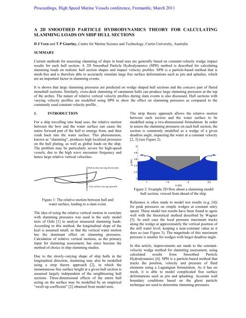
a 2d smoothed particle hydrodynamics theory for calculating
a 2d smoothed particle hydrodynamics theory for calculating
a 2d smoothed particle hydrodynamics theory for calculating

Create successful ePaper yourself
Turn your PDF publications into a flip-book with our unique Google optimized e-Paper software.
Proceedings, High Speed Marine Vessels conference, Fremantle, March 2011<br />
A 2D SMOOTHED PARTICLE HYDRODYNAMICS THEORY FOR CALCULATING<br />
SLAMMING LOADS ON SHIP HULL SECTIONS<br />
D J Veen and T P Gourlay, Centre <strong>for</strong> Marine Science and Technology, Curtin University, Australia<br />
SUMMARY<br />
Current methods <strong>for</strong> assessing slamming of ships in head seas are generally based on constant-velocity wedge impact<br />
results <strong>for</strong> each hull section. A 2D Smoothed Particle Hydrodynamics (SPH) method is described <strong>for</strong> <strong>calculating</strong><br />
slamming loads on realistic hull section shapes and impact velocity profiles. SPH is a <strong>particle</strong>-based method that is<br />
mesh-free and is there<strong>for</strong>e able to accurately simulate large free surface de<strong>for</strong>mations such as jets and splashes, which<br />
are an important factor in slamming events.<br />
It is shown that large slamming pressures are predicted on wedge shaped hull sections and the concave part of flared<br />
monohull sections. Similarly, cross-deck slamming of catamaran hulls can produce large slamming pressures at the top<br />
of the arches. The nature of relative vertical velocity profiles during slam events is also discussed. Hull sections with<br />
varying velocity profiles are modelled using SPH to show the effect on slamming pressures as compared to the<br />
commonly used constant velocity profile.<br />
1. INTRODUCTION<br />
For a ship travelling into head seas, the relative motion<br />
between the bow and the water surface can cause the<br />
entire <strong>for</strong>ward part of the hull to emerge from, and then<br />
crash back into the water surface. This phenomenon,<br />
known as “slamming”, produces high localized pressures<br />
on the hull plating, as well as global loads on the ship.<br />
The problem may be particularly severe <strong>for</strong> high-speed<br />
vessels, due to the high wave encounter frequency and<br />
hence large relative vertical velocities.<br />
Hull section moving downwards<br />
Free surface moving upwards<br />
Figure 1: The relative motion between hull and<br />
water surface, leading to a slam event.<br />
The idea of using the relative vertical motion to correlate<br />
with slamming pressures was used in the early model<br />
tests of Ochi [1] to analyse measured slamming loads.<br />
According to this method, the longitudinal slope of the<br />
keel is assumed small, so that the vertical water motion<br />
has the dominant effect on slamming pressures.<br />
Calculation of relative vertical motions, as the primary<br />
input <strong>for</strong> slamming assessment, has since become the<br />
method of choice in ship slamming studies.<br />
Due to the slowly-varying shape of ship hulls in the<br />
longitudinal direction, slamming may also be modelled<br />
using a strip <strong>theory</strong> approach [2], in which the<br />
instantaneous free surface height at a given hull section is<br />
assumed largely independent of the neighbouring hull<br />
sections. Three-dimensional effects of the entire hull<br />
acting on the surface may be modelled by an empirical<br />
“swell-up coefficient” [2] obtained from model tests.<br />
The strip <strong>theory</strong> approach allows the relative motion<br />
between each section and the water surface to be<br />
modelled using a two-dimensional <strong>for</strong>mulation. In order<br />
to assess the slamming pressures on each hull section, the<br />
section is commonly modelled as a wedge of a given<br />
deadrise angle, impacting the water at a constant velocity<br />
[2, 3] (see Figure 2).<br />
Figure 2: Example 2D flow about a slamming model<br />
hull section, viewed from ahead of the ship.<br />
Reference is often made to model test results (e.g. [4])<br />
<strong>for</strong> peak pressures on simple wedges at constant entry<br />
speed. These model test results have been found to agree<br />
well with the theoretical method described by Wagner<br />
[5]. In each case the local pressure maximum tracks<br />
along the wedge at approximately the vertical position of<br />
the still water level, keeping a near-constant value as it<br />
does so (see Figure 3). The magnitude of this maximum<br />
pressure is smaller <strong>for</strong> wedges with larger deadrise angle.<br />
In this article, improvements are made to the constantvelocity<br />
wedge method <strong>for</strong> slamming assessment, using<br />
calculated results from Smoothed Particle<br />
Hydrodynamics [6]. SPH is a <strong>particle</strong>-based method that<br />
tracks the position, velocity and pressure of fluid<br />
elements using a Lagrangian <strong>for</strong>mulation. As it has no<br />
mesh, it is able to model complicated free surface<br />
de<strong>for</strong>mations such as jets and splashing. Accurate wall<br />
boundary conditions based on the ghost <strong>particle</strong><br />
technique are used to determine slamming pressures.
Figure 3: Instantaneous pressure distribution<br />
<strong>for</strong> a 30º deadrise wedge model with a<br />
constant vertical velocity of 2.0m/s.<br />
2. EFFECT OF HULL SECTION SHAPE<br />
Existing seakeeping software (e.g. [3]) typically<br />
approximates each hull section as an equivalent wedge<br />
and only calculates slamming pressures near the keel.<br />
The use of an SPH simulation allows slamming pressures<br />
to be determined over the entire section, which is<br />
particularly important in the case of flared hulls.<br />
Measured slamming pressures [7] and observed damage<br />
[8] on vessels with significant bow flare has shown that<br />
particular areas of such hull sections may experience<br />
very high slamming pressures. Figure 4 describes the free<br />
surface impact, calculated using the SPH method, of the<br />
highly-flared hull section [9] described in Section 4. In<br />
this case, the initial impact speed is 0.6m/s. The peak<br />
pressure reaches a value of 5.5 kPa on the keel, 6.0 kPa<br />
on the concave part of the section, and 5.5 kPa just<br />
beneath the knuckle. So <strong>for</strong> flared hull sections it is<br />
insufficient to assume that the peak pressure occurs only<br />
at the keel, as done in many seakeeping methods.<br />
Figure 4: SPH pressure field surrounding the<br />
Aarsnes [9] freely-decelerating model test hull section<br />
0.13s after initial impact with the free surface.<br />
Another hull <strong>for</strong>m which requires special attention is the<br />
catamaran, where the cross-deck structure may impact<br />
the water surface (commonly termed wet-deck<br />
slamming). In this case, large slamming pressures may<br />
occur in the arches of the cross-deck structure [10],<br />
resulting in the hull experiencing significant loads. An<br />
example SPH pressure field of a 2D catamaran with a<br />
centre bow is illustrated in Figure 5.<br />
Figure 5: SPH pressure field surrounding<br />
the Whelan [10] freely-decelerating catamaran model<br />
hull section 0.07s after initial impact with<br />
the free surface at 1.0 m/s.<br />
3. EFFECT OF TIME-VARYING IMPACT<br />
VELOCITY<br />
In practice, bow impacts do not occur at constant relative<br />
vertical velocity. For minor slamming, the loads do not<br />
affect the overall heave and pitch of the vessel and the<br />
relative vertical velocity of the bow follows a nearsinusoidal<br />
motion [11, 12]. For major slamming, an<br />
upward <strong>for</strong>ce is exerted on the bow which modifies the<br />
heave and pitch accordingly. There<strong>for</strong>e, using the initial<br />
impact velocity as a constant vertical velocity to model<br />
slamming will cause over-estimation of the pressures<br />
above the keel, since in practice significant deceleration<br />
has occurred by the time these parts of the hull section hit<br />
the water (if at all).<br />
The effect of time-varying impact velocity has been<br />
studied experimentally using drop tests [10]. Whelan<br />
[10] dropped freely a variety of model hull sections from<br />
differing heights above still water and recorded the loads<br />
and local pressure experienced. A 2D SPH model of the<br />
15º deadrise wedge studied in [10] was created with<br />
matching physical parameters, a beam of 0.5 m and a<br />
mass of 74 kg. Three numerical pressure sensors were<br />
also placed in the same location as those used in [10] (see<br />
Figure 6).<br />
Figure 6: Diagram of the 15º deadrise wedge studied in<br />
[10] including pressure sensors P1, P2 and P3.
Figure 7: The vertical speed (a), <strong>for</strong>ce (b) and<br />
pressure at sensors P1 (c) and P2 (d) <strong>for</strong> a 15º<br />
deadrise wedge dropped from a height of 0.13m.<br />
The vertical velocity profile <strong>for</strong> the simple case of a 15º<br />
deadrise wedge dropped from a height of 0.13m is<br />
described in Figure 7a. The vertical velocity of the<br />
simulated wedge initially follows that recorded during<br />
the experiment [10], but the SPH model does decelerate<br />
more rapidly after 0.1s. Without including air in the SPH<br />
model, compression effects near the free surface are<br />
ignored, resulting in a higher simulated <strong>for</strong>ce. This in<br />
turn is the cause of the more rapid SPH deceleration.<br />
A second SPH simulation of the same wedge was also<br />
completed at a constant speed of 1.57 m/s, the initial<br />
entry speed of the experimental wedge. Comparing the<br />
peak vertical <strong>for</strong>ce in both simulations, the wedge in the<br />
constant velocity case was found to have approximately<br />
four times greater peak <strong>for</strong>ce than the variable-speed<br />
SPH case. Good agreement was found between the SPH<br />
and experimental results.<br />
The larger vertical <strong>for</strong>ce recorded during the constant<br />
velocity SPH water entry is caused by differences in the<br />
fluid pressure, evident at sensors P1 and P2 (see Figures<br />
7c and 7d). The pressure at P1 (Figure 7c) is very similar<br />
<strong>for</strong> both SPH simulations, reaching a peak approximately<br />
0.005s after the vertex strikes the water surface.<br />
However, by the time the peak pressure is experienced at<br />
P2 (Figure 7d), approximately 0.013s after the vertex<br />
strikes the water surface, the variable entry speed wedge<br />
has decelerated (Figure 7) and the resulting pressure is<br />
much smaller than the constant speed SPH simulation.<br />
Furthermore the constant velocity SPH pressure recorded<br />
at both sensors after the initial peak remains considerably<br />
higher than both the variable entry speed SPH wedge and<br />
experimental wedge, further increasing the measured<br />
vertical <strong>for</strong>ce.<br />
In summary, by comparing the experimental and SPH<br />
variable entry speed results, it can be seen that the SPH<br />
model is able to accurately simulate the pressures and net<br />
vertical <strong>for</strong>ce on a wedge during water entry.<br />
4. FLARED HULL WITH TIME-VARYING<br />
IMPACT VELOCITY<br />
Aarsnes [9] per<strong>for</strong>med drop tests on a model flared hull<br />
bow section and measured the total load, slamming<br />
pressures and deceleration profile. The hull section and<br />
the location of the four pressure sensors are illustrated in<br />
Figure 8. The length and beam of the model were 1.0m<br />
and 0.32m respectively, while the mass of the falling rig<br />
was 261kg.<br />
The drop test impact was modelled using the SPH<br />
methods described in [6], with a resolution of 400<br />
<strong>particle</strong>s per metre. The curved hull was approximated by<br />
a series of straight-line segments (see Figure 8), and the<br />
ghost <strong>particle</strong> method (see [6]) used to provide the wall<br />
boundary condition. The model was allowed to<br />
dynamically respond to the calculated vertical<br />
hydrodynamic <strong>for</strong>ce.
Figure 8: The flared hull section drop tested by Aarsnes<br />
[9]. The location of pressure sensors P1-P4 is illustrated<br />
on the right-hand side and the straight-line segment<br />
vertices <strong>for</strong> SPH modelling are shown on the left.<br />
The vertical velocity, <strong>for</strong>ce and pressure at sensors P2 and<br />
P3, measured when the hull section was dropped (freely<br />
in the vertical direction) from a height of 0.32m, are<br />
illustrated in Figure 9. The measured [9] and simulated<br />
(SPH) vertical <strong>for</strong>ces agree well, however there is some<br />
difference in the vertical speed profile. One possible<br />
cause of this difference is friction in the falling rig (not<br />
accounted <strong>for</strong> in the vertical <strong>for</strong>ce measurements)<br />
decreasing the vertical speed.<br />
The higher SPH impact velocity is evident in the pressure<br />
recorded at sensors P2 and P3. The SPH peaks occur<br />
sooner and have a slightly higher magnitude than those<br />
recorded by Aarsnes [9].<br />
From the results obtained it is clear that the SPH method<br />
is able to model the dynamic problem of slamming<br />
pressures on a decelerating object with reasonable<br />
accuracy.<br />
5. RELATIVE VERTICAL VELOCITY<br />
PROFILES<br />
The drop test experiments described above illustrate the<br />
effect of varying vertical velocity, but are not quite<br />
representative of the real impact velocity profile of a ship<br />
in a seaway. In that case, each hull section is constrained<br />
by its connection to adjacent hull sections, and the<br />
motions must be calculated <strong>for</strong> the ship as a whole. For<br />
minor slamming, the relative vertical velocity follows a<br />
sinusoidal pattern [11, 12], which can be calculated<br />
independently of the slamming loads [2]. For major<br />
slamming, the loads must be calculated and fed back into<br />
the seakeeping analysis.<br />
Calculating the overall slamming motions of a ship, by<br />
combining seakeeping and 2D SPH analysis, is a topic of<br />
ongoing research which is due to be published shortly by<br />
the authors.<br />
Figure 9: The vertical speed (a), <strong>for</strong>ce (b) and<br />
pressure at sensors P2 (c) and P3 (d) <strong>for</strong> the Aarsnes<br />
[9] hull section dropped from a height of 0.31m.
6. CONCLUSIONS<br />
For minor slamming impacts of wedge-shaped hull<br />
sections, where the only point of interest is the keel,<br />
existing strip <strong>theory</strong> methods based on constant-velocity<br />
wedge impacts are appropriate. However, in order to<br />
model slamming pressures higher up the hull (such as<br />
near the knuckle of flared sections) alternative methods<br />
are needed. Such methods must account <strong>for</strong> the changing<br />
shape of the hull, as well as the varying impact velocity<br />
as the hull enters the water.<br />
For major slamming impacts, even of wedge-shaped<br />
sections, the slamming loads affect the global heave and<br />
pitch motions, and need to be calculated over the entire<br />
hull section rather than just at the keel.<br />
Smoothed Particle Hydrodynamics (SPH) has been put<br />
<strong>for</strong>ward in this article as an appropriate solution to these<br />
deficiencies. It is able to model a wide range of straight<br />
or curved sectional shapes, through use of a ghost<br />
<strong>particle</strong> wall boundary condition. As a mesh-free method,<br />
SPH can model the jets and splashing which are<br />
important features of slam events. SPH is also able to<br />
cope with any prescribed velocity profile, or alternatively<br />
calculate vertical <strong>for</strong>ces to modify the velocity profile as<br />
required.<br />
7. REFERENCES<br />
[1] OCHI, M.K., Model experiments on ship strength and<br />
slamming in regular waves, Transactions of the Royal<br />
Society of Naval Architects and Marine Engineers 66:<br />
345-383, 1958.<br />
[2] LLOYD, A.R.J.M., ‘Seakeeping: Ship Behaviour in<br />
Rough Weather’, Ellis Horwood, 1989.<br />
[3] JOURNEE, J.M.J, ADEGEEST, L.J.M., Theoretical<br />
Manual of Strip Theory Program “Seaway <strong>for</strong><br />
Windows”, TU Delft Report 1370, 2003.<br />
[4] HAGIWARA, K., YUHARA, T., Study of wave<br />
impact load on ship bow, Japan Shipbuilding and Marine<br />
Engineering, Vol. 8, No. 4, 1974.<br />
[5] WAGNER, H., The phenomena of impacts and<br />
sliding on liquid surfaces. NACA translation 1366,<br />
National Advisory Committee <strong>for</strong> Aeronautics,<br />
Washington, 1932.<br />
[6] VEEN, D.J., A Smoothed Particle Hydrodynamics<br />
Study of Ship Bow Slamming in Ocean Waves, Ph.D.<br />
thesis, Centre <strong>for</strong> Marine Science and Technology,<br />
Curtin University.<br />
[7] VULOVICH, R., HIRAYAMA, T., TOKI, N.,<br />
MIZUNO, H., Characteristics of hull stresses measured<br />
on a large containership in rough seas. Transactions of<br />
the Society of Naval Architects and Marine Engineers<br />
97: 397-428, 1989.<br />
[8] YAMAMOTO, Y., IIDA, K., FUKUSAWA, T.,<br />
MURAKAMI, T., ARAI, M., ANDO, A., Structural<br />
damage analysis of a fast ship due to bow flare<br />
slamming. International Shipbuilding Progress 32 (369):<br />
124-136, 1985.<br />
[9] AARSNES, J.V., Drop test with ship sections - effect<br />
of roll angle, Report No. 603834.00.01, Norwegian<br />
Marine Technology Research Institute, Trondheim,<br />
Norway, 1996.<br />
[10] WHELAN, J.R., Wetdeck slamming of high-speed<br />
catamarans with a centre bow, Ph.D. Thesis, School of<br />
Engineering, University of Tasmania, Hobart, 2004.<br />
[11] HERMUNDSTAD, O.A., MOAN, T., Numerical<br />
and experimental analysis of bow flare slamming on a<br />
Ro-Ro vessel in regular oblique waves. Journal of<br />
Marine Science and Technology 10: 105-122, 2005.<br />
[12] SEBASTIANI, L., VALDENAZZI, F., GROSSI, L.,<br />
KAPSENBERG, G.K., A theoretical/experimental<br />
investigation of the slamming pressures on fast monohull<br />
vessels. In Proceedings of the 6th International<br />
Conference on Fast Sea Transportation, Southampton,<br />
UK, 2001.<br />
7. AUTHORS’ BIOGRAPHY<br />
Daniel Veen has recently submitted his Ph.D. thesis at<br />
the Centre <strong>for</strong> Marine Science and Technology (CMST),<br />
Curtin University. He has developed a Smoothed Particle<br />
Hydrodynamics code from first principles, and is now<br />
using it to model complex free surface problems such as<br />
ship slamming.<br />
Tim Gourlay is a Senior Research Fellow in ship<br />
<strong>hydrodynamics</strong> at CMST. He has supervised Daniel<br />
Veen’s Ph.D. thesis and is continuing research on the<br />
topic of SPH.