ORNL-1816 - the Molten Salt Energy Technologies Web Site
ORNL-1816 - the Molten Salt Energy Technologies Web Site ORNL-1816 - the Molten Salt Energy Technologies Web Site
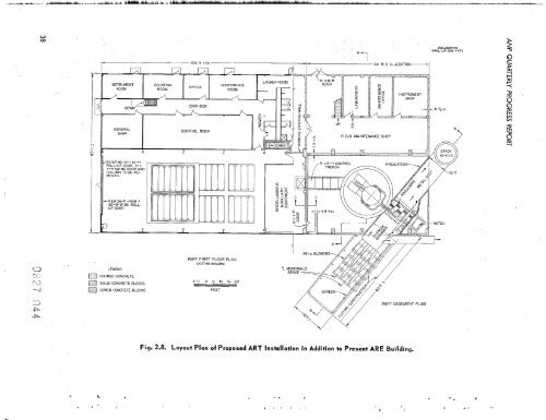
t INSTRUMENT CONFERENCE -NEW 26-ft-HIGH X 30-ft-WIDE ROLL- UP DOOR. -, LEGEND POURED CONCRETE SOLID CONCRETE BLOCKS @ CORED CONCRETE BLOCKS * 1 ‘ . I ’ # CONTROL ROOM - PART FIRST FLOOR PLAN EXISTING BUILDING 2 0 4 8 12 16 20 FEET 48-in. BLOWERS ”’ yp 64 ft 0 in. ADDITION -1 k5 FIELD MAINTENANCE SHOP PART BASEMENT PLAN Fig. 2.8. Layout Plan of Proposed ART Installation in Addition to Present ARE Building. UNCLASSIFIED ORNL-LR-DWG 4471 5J -i 2 !7 2 0 XJ z:
the floor up to 3 ft below the bolting flange level. The reactor tank location would be approximately centered in the 42-ft-wide, 64-ft-long high-bay ex- tension directly in line with the ARE experimental bay. The reactor would be positioned so that the top of the shield would be at the building floor elevation. To permit use of the experimental pits for instal- lation of auxiliary equipment, to permit possible underwater reactor disassembly work after reactor operation, and to provide a large entry door to the ART area, the south wall of the ARE experimental bay would be removed, the overhead crane facility would be revised from 10- to 20-ton capacity, and the truck door in the north wall of the ARE Building would be enlarged. The double-walled tank described above is essentially the container considered for this instal- lation. The inner tank, or pressure vessel, would be approximately 24 ft in diameter with a straight section about 11 ft long and a hemispherical bottom and top. The joint between the removable top and the lower portion of the tank would probably be a bolting flange, with provision for sealing the joint with a low-melting-point alloy. Thus the top would be used only as required by the operating program. The outer tank would be a right circular cylinder approximately 27 ft in diameter and about 47'/, ft high. About 26 ft of this water-containing tank would be above floor grade, and this portion of the tank would be attached by a flange or weld joint only when the operating program required that the upper hemisphere of the inner tank be in place. The inner tank would be set coaxially with the PERIOD ENDING DECEMBER 10,1954 movement of the portable fluoride fuel and sodium moderator coolant containers to their operating stations under the reactor. The off-center location would also serve to minimize the length of NaK piping that must run from the reactor through a bulkhead in the pressure vessel to the he'gt dump radiators outside the tank. Quite a variety of shields has been corisidered for the ART. The most convenient seems to be one functionally the same as that for an aircraft requiring a unit shield, namely, a shield designed to give 1 r/hr at 50 ft from the center of the reactor. Such a shield is both the lightest and mast com- pact that has been devised. It makes use of non- critical materials that are in good supply, and it will provide useful performance data on the effects of the release of delayed neutrons ancl decay gammas in the heat exchanger, the generation of secondary gammas throughout the shield, etc. While the complication of detailed instrumentation within the shield does not appear to be warranted, it will be extremely worthwhile to obtain radiation dose level data at various points around the pe- riphery of the shield, particularly in the vicinity of the ducts and the pump and expansion tank region. Several arrangements have been considered as a means for disposing of the heat generated in the reactor. The most promising is one that resembles a turbojet power plant in many respects. It em- ploys radiators essentially similar to tho:je suit- able for turbojet operation. Conventional axial-flow blowers would be employed to force cooling air through the radiators. This arrangement is flexible This positioning would provide needed space for radiators would be mounted in an air tunnel which 39
- Page 1: ORNL DOCUMENT REFERENCE LIBRARY, Y-
- Page 4 and 5: .. II 1. G. M. Adamson 2. R. G. Aff
- Page 6 and 7: iv R ports pr ri ORNL-528 ORNL-629
- Page 8 and 9: t s
- Page 10 and 11: 4 . CRITICAL EXPERIMENTS ..........
- Page 12 and 13: Removal of Xe13' from Molten Fluori
- Page 14 and 15: ANP QUARTERLY PROGRESS REPORT main
- Page 16 and 17: ANP QUARTERLY PROGRESS REPORT 26OOC
- Page 18 and 19: ANP QUARTERLY PROGRESS REPORT syste
- Page 20 and 21: incident on crew shield sides and r
- Page 23 and 24: 1. CIRCULATING-FUEL AIRCRAFT REACTO
- Page 25 and 26: clean reactor at a low power for a
- Page 27 and 28: for more than 0.6 Mw in the sodium,
- Page 29 and 30: I .o 08 0.6 . E - ‘z I - 0.4 0.2
- Page 31 and 32: i PERIOD ENDING DECEMBER 70,7954 Fi
- Page 33 and 34: Analytical studies, layout work, an
- Page 35 and 36: XENON- REMOVAL SYSTEM 4 BLEED CIRCU
- Page 37 and 38: c. . f 0 L .. would mean that most
- Page 39 and 40: ‘s = = (tot a I f i s s ion s/sec
- Page 41 and 42: L . PERIOD ENDING DECEMBER 70, 7954
- Page 43 and 44: PERIOD ENDING DECEMBER 70, 7954
- Page 45 and 46: PERIOD ENDING DECEMBER 70, 7954 Fig
- Page 47 and 48: A" d OIL IN-l OIL IN-2 NUCLEAR I N
- Page 49: 7 . " e- It should be noted that th
- Page 53 and 54: " i' Design work is under way on an
- Page 55 and 56: The pump has unusual ability to rem
- Page 57 and 58: into operation with a Reynolds numb
- Page 59 and 60: . . . . .- . Fig. 3.5. Heat Exchang
- Page 61 and 62: TABLE 3.1. GAS-FIRED FURNACE OPERAT
- Page 63 and 64: n while connected to a small tank o
- Page 65 and 66: Fig. 4.1. Second Reflector-Moderate
- Page 67: - . c ' t P - 9 Part I MATERIALS RE
- Page 70 and 71: ANP QUARTERLY PROGRESS REPORT 58 4e
- Page 72 and 73: ANP QUARTERLY PROGRESS REPORT UF, S
- Page 74 and 75: ANP QUARTERLY PROGRESS REPORT wheth
- Page 76 and 77: ANP QUARTERLY PROGRESS REPORT In th
- Page 78 and 79: 1Y PROGRESS REPORT y equilibration
- Page 80 and 81: ANP QUARTERLY PROGRESS REPORT were
- Page 82 and 83: ANP QUARTERLY PROGRESS REPORT Conse
- Page 84 and 85: AN P QUARTERLY PROGRESS R €PO RT
- Page 86 and 87: ANP QUARTERLY PROGRESS REPORT TABLE
- Page 88 and 89: ANP QUARTERLY PROGRESS REPORT Studi
- Page 90 and 91: ANP QUARTERLY PROGRESS REPORT TABLE
- Page 92 and 93: 1 ANP QUARTERLY PROGRESS REPORT 19.
- Page 94 and 95: ANP QUARTERLY PROGRESS REPORT TABLE
- Page 96 and 97: ANP QUARTERLY PROGRESS REPORT appea
- Page 98 and 99: 1 I I I . . ANP QUARTERLY PROGRESS
t<br />
INSTRUMENT CONFERENCE<br />
-NEW 26-ft-HIGH X<br />
30-ft-WIDE ROLL-<br />
UP DOOR.<br />
-,<br />
LEGEND<br />
POURED CONCRETE<br />
SOLID CONCRETE BLOCKS<br />
@ CORED CONCRETE BLOCKS<br />
* 1 ‘ . I ’<br />
#<br />
CONTROL ROOM<br />
-<br />
PART FIRST FLOOR PLAN<br />
EXISTING BUILDING<br />
2 0 4 8 12 16 20<br />
FEET<br />
48-in. BLOWERS<br />
”’<br />
yp 64 ft 0 in. ADDITION -1 k5<br />
FIELD MAINTENANCE SHOP<br />
PART BASEMENT PLAN<br />
Fig. 2.8. Layout Plan of Proposed ART Installation in Addition to Present ARE Building.<br />
UNCLASSIFIED<br />
<strong>ORNL</strong>-LR-DWG 4471<br />
5J<br />
-i<br />
2<br />
!7<br />
2<br />
0<br />
XJ<br />
z:<br />


