ORNL-1816 - the Molten Salt Energy Technologies Web Site
ORNL-1816 - the Molten Salt Energy Technologies Web Site ORNL-1816 - the Molten Salt Energy Technologies Web Site
ANP QUARTERLY PROGRESS REPORT Fig. 1.8. Weld Crack. Cross Section Through Thermocouple below criticality or at very low power levels. Samples were withdrawn by pressurizing the pump bowl sufficiently to cause flow through a heated lnconel tube into a sampling device, which was constructed to allow line flushing before col- lection of the sample. Analyses of the samples were carried out by the ANP Analytical Chemistry Group and are shown in Table 1.1. As may be seen, the chromium content of the fuel was essentially constant at 100 ppm after 155 hr of circulation of the fuel carrier through the reactor. If corrosion of the lnconel is assumed to have been uniform over the surface of the system - and since it was operating isothermally during this period, such an assumption is reasonable - the chromium con- centration of 100 ppm would represent about 0.5 20 TABLE 1.1. ARE FUEL SAMPLE ANALYSES Hours After Filling with Barren Carrier 19 60 110 1 55 157 178 182 205 242 24 6 268 286 3 07 Uranium Chromium (wt X) (PPm) 1.84 3.45 5.43 9.54 12.21 12.27 12.54 12.59 13.59 81 90 102 100 150 190 2 00 205 300 320 37 8 420 445 mil of attack on the Inconel. As was anticipated, the chromium content of the melt was found to increase a few hours after each addition of fuel concentrate (Na,UF,). By the time the final sample was taken, after 307 hr of molten fluoride circulation, the chromium content was found to be 445 ppm. Again, if a uniform rate of attack of the lnconel is assumed and if the removal of circulated material from the system during this time (to maintain desired pump liquid level) is taken into account, this chromium content would represent about 5 mils of attack on the lnconel system. If the data in Table 1.1 are plotted as chromium content vs time, it is seen that the chromium content had begun to level off by the time the final sample was taken. A projection of the slope of the chromium curve indicates a maximum chromium concentration of about 600 ppm after several hundred hours of operation. There is no doubt that mass transfer of chromium metal began soon after power operation started, since there were then large temperature differentials across portions of the system. Sampling was not possible at this time and could not, of course, have given information on mass transfer. Heat transfer characteristics of the ARE did not appear to have changed during its 150 Mwhr of operation, and so whatever mass transfer occurred was unimportant. Details of mass transfer will be studied when sectioning of the equipment becomes possible.
Analytical studies, layout work, and detail design have proceeded on both the reactor assembly and the installation for the Aircraft Reactor Test (ART), formerly the Circulating-Fuel Reactor Experiment (CFRE). Work has also continued on the component development tests outlined in the previous report. ' Reports have been completed on the high-power-dens ity beryllium thermal stress test and the first fuel-to-NaK heat exchanger t e ~ t . Specifications ~ ~ ~ have been completed for radiators to be used as heat dumps in heat exchanger tests. It is expected that essentially the same specifications can be used for procurement of the radiators for the ART heat dumps and that endurance test experience gained in the course of these smal I heat exchanger component development tests will establish the reliability of the product of at least one vendor. EXPANSION-TANK AND XENON- REMOVAL SYSTEM G. Samuels Aircraft Reactor Engineering Division W. Lowen, Consultani Recent work on the expansion-tank, fuel-pump, and xenon-removal system has been directed primarily toward the development of a hydraulic circuit that performs all the various functions required of the system. The basic components and their principal functions were described in an earlier re~ort~ and may be summarized 2. REFLECTOR-MODERATED REACTOR A. P. Fraas Aircraft Reactor Engineering Division ?at Exchanger 1 est, PERIOD ENDING DECEMBER 70, 7954 for the main fuel system with a liquid surface that is stable for all attitudes (in flight); (3) a centri- fuge cup integrally mounted on the back of each fuel pump impeller for degassing the processed fuel, pumping the processed fuel back into the main system, and providing a seal for the fuel Pump. Several Lucite models that differ in cornponent design and circuit arrangement have been built and tested, and they have led to the design illustrated in Fig. 2.1. In this model the swirl chamber is mounted between the two fuel pumps ancl raised above the centrifuge cups to assure their priming under starting conditions. The swirl in the chamber is produced in two v?ays: by nozzles located in the swirl chamber floor and by swirl pumps which are needed to maintain a high swirl velocity when the fuel level rises above the 25% full condition owing to thermal expansion in the main system. The nozzles and swirl pumps are arranged to deliver high-velocity fuel jets tcmgentially at the periphery of the swirl chamber to give good agitation and to assure a strong centrifugal field and a stable free surface. The nozzles serve both to meter the bleed flow through the expansion tank and to control the fuel pump suction pressure relative to the swirl chamber gas pressure. This important function is perhaps more evident in the schematic circuit analog presented in Fig. 2.2. By tracing the bleed flow, it can be seen that the pressure drop across the nozzles approximates the heat exchanger resistance. Consequently, the fuel pump suction pressure is maintained near the helium pressure existing in the swirl chamber. The configuration of nozzles and part:: is so Of L xenon -. proportioned as to oversupply the centrifuge fuel 4R2. w. ~~~~~~d and A. p. F ~ ANP ~ euar. ~ prog. ~ , within the bleed circuit contributes toward stabilizing the three free surfaces inherent in this ' Rep. Dec. 10, 1953, ORNL-1649, p 39, layout. 21
- Page 1: ORNL DOCUMENT REFERENCE LIBRARY, Y-
- Page 4 and 5: .. II 1. G. M. Adamson 2. R. G. Aff
- Page 6 and 7: iv R ports pr ri ORNL-528 ORNL-629
- Page 8 and 9: t s
- Page 10 and 11: 4 . CRITICAL EXPERIMENTS ..........
- Page 12 and 13: Removal of Xe13' from Molten Fluori
- Page 14 and 15: ANP QUARTERLY PROGRESS REPORT main
- Page 16 and 17: ANP QUARTERLY PROGRESS REPORT 26OOC
- Page 18 and 19: ANP QUARTERLY PROGRESS REPORT syste
- Page 20 and 21: incident on crew shield sides and r
- Page 23 and 24: 1. CIRCULATING-FUEL AIRCRAFT REACTO
- Page 25 and 26: clean reactor at a low power for a
- Page 27 and 28: for more than 0.6 Mw in the sodium,
- Page 29 and 30: I .o 08 0.6 . E - ‘z I - 0.4 0.2
- Page 31: i PERIOD ENDING DECEMBER 70,7954 Fi
- Page 35 and 36: XENON- REMOVAL SYSTEM 4 BLEED CIRCU
- Page 37 and 38: c. . f 0 L .. would mean that most
- Page 39 and 40: ‘s = = (tot a I f i s s ion s/sec
- Page 41 and 42: L . PERIOD ENDING DECEMBER 70, 7954
- Page 43 and 44: PERIOD ENDING DECEMBER 70, 7954
- Page 45 and 46: PERIOD ENDING DECEMBER 70, 7954 Fig
- Page 47 and 48: A" d OIL IN-l OIL IN-2 NUCLEAR I N
- Page 49 and 50: 7 . " e- It should be noted that th
- Page 51 and 52: the floor up to 3 ft below the bolt
- Page 53 and 54: " i' Design work is under way on an
- Page 55 and 56: The pump has unusual ability to rem
- Page 57 and 58: into operation with a Reynolds numb
- Page 59 and 60: . . . . .- . Fig. 3.5. Heat Exchang
- Page 61 and 62: TABLE 3.1. GAS-FIRED FURNACE OPERAT
- Page 63 and 64: n while connected to a small tank o
- Page 65 and 66: Fig. 4.1. Second Reflector-Moderate
- Page 67: - . c ' t P - 9 Part I MATERIALS RE
- Page 70 and 71: ANP QUARTERLY PROGRESS REPORT 58 4e
- Page 72 and 73: ANP QUARTERLY PROGRESS REPORT UF, S
- Page 74 and 75: ANP QUARTERLY PROGRESS REPORT wheth
- Page 76 and 77: ANP QUARTERLY PROGRESS REPORT In th
- Page 78 and 79: 1Y PROGRESS REPORT y equilibration
- Page 80 and 81: ANP QUARTERLY PROGRESS REPORT were
ANP QUARTERLY PROGRESS REPORT<br />
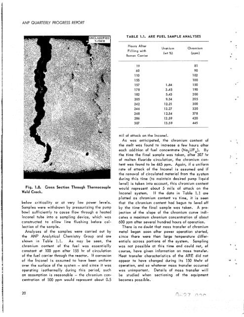
Fig. 1.8.<br />
Weld Crack.<br />
Cross Section Through Thermocouple<br />
below criticality or at very low power levels.<br />
Samples were withdrawn by pressurizing <strong>the</strong> pump<br />
bowl sufficiently to cause flow through a heated<br />
lnconel tube into a sampling device, which was<br />
constructed to allow line flushing before col-<br />
lection of <strong>the</strong> sample.<br />
Analyses of <strong>the</strong> samples were carried out by<br />
<strong>the</strong> ANP Analytical Chemistry Group and are<br />
shown in Table 1.1. As may be seen, <strong>the</strong><br />
chromium content of <strong>the</strong> fuel was essentially<br />
constant at 100 ppm after 155 hr of circulation<br />
of <strong>the</strong> fuel carrier through <strong>the</strong> reactor. If corrosion<br />
of <strong>the</strong> lnconel is assumed to have been uniform<br />
over <strong>the</strong> surface of <strong>the</strong> system - and since it was<br />
operating iso<strong>the</strong>rmally during this period, such<br />
an assumption is reasonable - <strong>the</strong> chromium con-<br />
centration of 100 ppm would represent about 0.5<br />
20<br />
TABLE 1.1. ARE FUEL SAMPLE ANALYSES<br />
Hours After<br />
Filling with<br />
Barren Carrier<br />
19<br />
60<br />
110<br />
1 55<br />
157<br />
178<br />
182<br />
205<br />
242<br />
24 6<br />
268<br />
286<br />
3 07<br />
Uranium Chromium<br />
(wt X) (PPm)<br />
1.84<br />
3.45<br />
5.43<br />
9.54<br />
12.21<br />
12.27<br />
12.54<br />
12.59<br />
13.59<br />
81<br />
90<br />
102<br />
100<br />
150<br />
190<br />
2 00<br />
205<br />
300<br />
320<br />
37 8<br />
420<br />
445<br />
mil of attack on <strong>the</strong> Inconel.<br />
As was anticipated, <strong>the</strong> chromium content of<br />
<strong>the</strong> melt was found to increase a few hours after<br />
each addition of fuel concentrate (Na,UF,). By<br />
<strong>the</strong> time <strong>the</strong> final sample was taken, after 307 hr<br />
of molten fluoride circulation, <strong>the</strong> chromium content<br />
was found to be 445 ppm. Again, if a uniform<br />
rate of attack of <strong>the</strong> lnconel is assumed and if<br />
<strong>the</strong> removal of circulated material from <strong>the</strong> system<br />
during this time (to maintain desired pump liquid<br />
level) is taken into account, this chromium content<br />
would represent about 5 mils of attack on <strong>the</strong><br />
lnconel system. If <strong>the</strong> data in Table 1.1 are<br />
plotted as chromium content vs time, it is seen<br />
that <strong>the</strong> chromium content had begun to level off<br />
by <strong>the</strong> time <strong>the</strong> final sample was taken. A projection<br />
of <strong>the</strong> slope of <strong>the</strong> chromium curve indicates<br />
a maximum chromium concentration of about<br />
600 ppm after several hundred hours of operation.<br />
There is no doubt that mass transfer of chromium<br />
metal began soon after power operation started,<br />
since <strong>the</strong>re were <strong>the</strong>n large temperature differentials<br />
across portions of <strong>the</strong> system. Sampling<br />
was not possible at this time and could not, of<br />
course, have given information on mass transfer.<br />
Heat transfer characteristics of <strong>the</strong> ARE did not<br />
appear to have changed during its 150 Mwhr of<br />
operation, and so whatever mass transfer occurred<br />
was unimportant. Details of mass transfer will<br />
be studied when sectioning of <strong>the</strong> equipment<br />
becomes possible.


