

ORNL-1816 - the Molten Salt Energy Technologies Web Site
ORNL-1816 - the Molten Salt Energy Technologies Web Site
ORNL-1816 - the Molten Salt Energy Technologies Web Site

Create successful ePaper yourself
Turn your PDF publications into a flip-book with our unique Google optimized e-Paper software.
1. CIRCULATING-FUEL AIRCRAFT REACTOR EXPERIMENT<br />
OPERATION OF THE AIRCRAFT REACTOR<br />
EXPERIMENT<br />
The Aircraft Reactor Exper iment was success-<br />
fully operated during <strong>the</strong> quarter. Uranium in <strong>the</strong><br />
form of molten Na,UF, was added to <strong>the</strong> barren<br />
carrier, NaZrF,, with which <strong>the</strong> fuel system was<br />
initially filled, to make <strong>the</strong> reactor critical. The<br />
fuel composition at initial criticality was 52.8-<br />
41.5-5.7 mole 5% (RaF-ZrF,-UF,), which has a<br />
melting point of 990°F, whereas <strong>the</strong> final fuel<br />
mixture (which included excess uranium) had a<br />
composition of 53.2-40.5-6.3 mole % (NaF-ZrF,-<br />
UF,) and a melting point of 1000°F.<br />
It was initially intended to remotely add <strong>the</strong><br />
concentrate to <strong>the</strong> fuel system from a large tank<br />
which contained all <strong>the</strong> concentrate, after first<br />
passing. it through an intermediate transfer tank.<br />
This system was discarded when temperature-<br />
control and continuous-weight-measuring instru-<br />
mentation on <strong>the</strong> transfer tank proved to be un-<br />
satisfactory. Instead, a less elaborate, but more<br />
direct, method of concentrate addition was em-<br />
ployed. This enrichment operation involved <strong>the</strong><br />
successive connection of numerous smal I concen-<br />
trate containers to an intermediate transfer pot,<br />
which was, in turn, connected to <strong>the</strong> fuel system<br />
by a line which injected <strong>the</strong> concentrate in <strong>the</strong><br />
pump above <strong>the</strong> liquid level. Each of <strong>the</strong> concen-<br />
trate containers was weighed before and after a<br />
transfer in order to determine <strong>the</strong> amount of<br />
uranium injected into <strong>the</strong> system. The concentrate<br />
was supplied in batches in cans containing from<br />
about 0.25 Ib of Na,UF, (for rod calibration) up<br />
to about 33 Ib (as was used during <strong>the</strong> first<br />
subcritical loading). In <strong>the</strong> enrichment operation<br />
<strong>the</strong> pump bowl served as a mixing chamber and<br />
uniformly distributed <strong>the</strong> concentrate into <strong>the</strong><br />
circulating stream. (For details of <strong>the</strong> loading<br />
operation see -foliowing subsection on “Loading<br />
of <strong>the</strong> ARE.”)<br />
The first concentrate addition was made on<br />
October 30, but <strong>the</strong> reactor did not become critical<br />
until three days later (3:45 PM, November 3).<br />
Most of <strong>the</strong> intervening time was spent in clearing<br />
<strong>the</strong> end of <strong>the</strong> transfer line at <strong>the</strong> pump, which,<br />
because of limitations inherent to only this par-<br />
E. S. Bettis J. L. Meem<br />
Aircraft Reactor Engineering Division<br />
ticular design, was difficult to heat and even more<br />
difficult to service.<br />
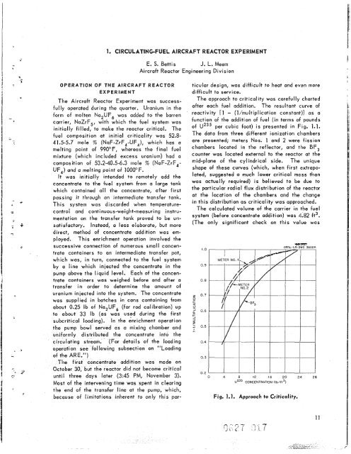
The approach to criticality was carefully charted<br />
after each fuel addition. The resultant curve of<br />
reactivity [I - (l/multiplication constant)] as a<br />
function of <strong>the</strong> addition of fuel (in terms of pounds<br />
of U235 per cubic foot) is presented in Fig. 1.1.<br />
The data from three different ionization chambers<br />
are presented; meters Nos. 1 and 2 were fission<br />
chambers located in <strong>the</strong> reflector, and <strong>the</strong> BF,<br />
counter was located external to <strong>the</strong> reactor at <strong>the</strong><br />
mid-plane of <strong>the</strong> cylindrical side. The unique<br />
shape of <strong>the</strong>se curves (which, when first (extrapo-<br />
lated, suggested a much lower critical mass than<br />
was actually required) is believed to be due to<br />
<strong>the</strong> particular radial flux distribution of <strong>the</strong> reactor<br />
at <strong>the</strong> location of <strong>the</strong> chambers and <strong>the</strong> change<br />
in this distribution as criticality was approached.<br />
The calculated volume of <strong>the</strong> carrier in <strong>the</strong> fuel<br />
system (before concentrate addition) was 4.82 ft3.<br />
(The only significant check on this value was<br />
1.0<br />
0.9<br />
0.8<br />
z 0.7<br />
0<br />
+<br />
0<br />
2 0.6<br />
-<br />
+<br />
-I 3<br />
I<br />
1 0.5<br />
-.<br />
0.4<br />
0.3<br />
02<br />
0 4 8 i2 16 20 24 28<br />
U235 CONCENTRATION (lb/ft3)<br />
Fig. 1.1. Approach to Criticality.
![Review of Molten Salt Reactor Physics Calculations [Disc 2]](https://img.yumpu.com/21979492/1/190x247/review-of-molten-salt-reactor-physics-calculations-disc-2.jpg?quality=85)


