

ORNL-1816 - the Molten Salt Energy Technologies Web Site
ORNL-1816 - the Molten Salt Energy Technologies Web Site
ORNL-1816 - the Molten Salt Energy Technologies Web Site

Create successful ePaper yourself
Turn your PDF publications into a flip-book with our unique Google optimized e-Paper software.
15. TOWER SHIELDING FACILITY<br />
C. E. Clifford<br />
T. V. Blosser<br />
J. L. Hull<br />
L, B. Holland<br />
F. N. Watson<br />
Physics Division<br />
D. L. Gilliland, General Electric Company<br />
M. F. Valerino, NACA, Cleveland<br />
J. Van Hoomi ssen, Boeing Airplane Company<br />
-ANP R-1 divided shield mockup<br />
ements of <strong>the</strong> radiation around<br />
<strong>the</strong> reactor shield in <strong>the</strong> Tower Shielding Facility<br />
(TSF) reactor handling pool. The experimentation<br />
thus far has also included <strong>the</strong>rmal-neutron flux and<br />
some aamma-ray dose rate measurements in <strong>the</strong><br />
ated a horizontal distance of<br />
shield. This work was in-<br />
of two and one-half weeks so<br />
e TSF could participate in an Air Force<br />
in which a group of monkeys were exposed<br />
massive neutron radiation doses. The work on<br />
<strong>the</strong> G-E experiment has now been resumed.<br />
Analyses of some aspects of <strong>the</strong> TSF data have<br />
been completed and are presented in Sec. 12,<br />
“Sh i el di n g An al y s i s. ”<br />
TSF EXPERIMENT WITH THE MOCKUP OF<br />
THE GE-ANP R-1 SHIELD DESIGN<br />
T. V. Blosser<br />
D. L, Gilliland<br />
J. Van Hoomissen<br />
F. N. Watson<br />
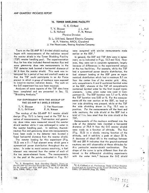
The mockup of <strong>the</strong> GE-ANP R-1 reactor shield<br />
design (Fig. 15.1) is being used at <strong>the</strong> TSF for a<br />
series of measurements. Fast-neutron and gamma-<br />
ray dose rates were measured around <strong>the</strong> reactor<br />
shield section while it was submerged in water in<br />
<strong>the</strong> reactor handling pool. In addition, <strong>the</strong>rmalneutron<br />
flux and gamma-ray dose rate measurements<br />
have been made in <strong>the</strong> detector tank located a<br />
fixed horizontal distance from <strong>the</strong> reactor shield.<br />
The reactor loading for this experiment (Fig.<br />
15.2) was a 5 x 7 fuel element array which gave a<br />
etrical power distribution throughout <strong>the</strong> retor.<br />
In order to avoid excess reactivity, a fuel<br />
t was removed from <strong>the</strong> center of each of<br />
-element faces. The measurements<br />
t <strong>the</strong> points indicated in Fiq. 15.1<br />
ulk Shielding Facility Tests on<br />
ShieldMockup, <strong>ORNL</strong> CF-54-8-94<br />
ANP Quar. Prog. Rep. Mar. 10,<br />
-<br />
were compared with similar measurements made<br />
earlier at <strong>the</strong> BSF.’<br />
In general, <strong>the</strong> BSF and TSF data were in agree-<br />
ment, as is indicated in Figs. 15.3 and 15.4. How-<br />
ever, <strong>the</strong>y were not in complete agreement, largely<br />
because of differences in <strong>the</strong> experimental setups<br />
at <strong>the</strong> two facilities. For example, while <strong>the</strong> TSF<br />
had a symmetrical power density distribution, <strong>the</strong><br />
fuel element loading at <strong>the</strong> BSF gave an asym-<br />
metrical distribution which had a maximum 8.1 cm<br />
from <strong>the</strong> center line of <strong>the</strong> reactor grid. Also,<br />
only compartments A and D contained borated water<br />
at <strong>the</strong> BSF, whereas at <strong>the</strong> TSF all compartments<br />
contained borated water for <strong>the</strong> first in-pool meas-<br />
urements. Later, plain water was used in Com-<br />
portment D. The BSF boration was 1.1 wt %, while<br />
<strong>the</strong> TSF boration was 0.85 wt %. For <strong>the</strong> measure-<br />
ments off <strong>the</strong> rear section at <strong>the</strong> BSF, no lead or<br />
iron side shielding was present, while at <strong>the</strong> TSF<br />
<strong>the</strong> side shielding shown in Fig. 15.1 was in<br />
position, For <strong>the</strong> measurements off <strong>the</strong> front and<br />
side sections, <strong>the</strong> side shield at <strong>the</strong> BSF had a<br />
total of 1 in. less steel than <strong>the</strong> side shield at <strong>the</strong><br />
TSF.<br />
Measurements of <strong>the</strong> neutrons scattered into <strong>the</strong><br />
side of <strong>the</strong> detector tank (located a horizontal<br />
distance of 70.8 ft from <strong>the</strong> G-E reactor shield)<br />
were made as a function of altitude. The flux<br />
(Fig. 15.5) is a slowly varying function of <strong>the</strong><br />
altitude, and it exhibits a peak at about 35 ft.<br />
A decrease of about 6% in <strong>the</strong> readings between<br />
150 and 200 ft indicates that <strong>the</strong> ground-scattered<br />
neutrons are still observable at <strong>the</strong>se altitudes for<br />
this particular reactor-shield combination. The<br />
shape of <strong>the</strong> curve is quite different from that ob-<br />
tained in <strong>the</strong> differential shielding experiments<br />
with <strong>the</strong> water tank,:! because <strong>the</strong> G-E shield<br />
2C. E. Clifford et aL, Preliminary Study of Fast Neutron<br />
Ground and Air Scattering at <strong>the</strong> Tower Shielding Facility,<br />
<strong>ORNL</strong> CF-54-8-95 (Aug. 23, 19541.
![Review of Molten Salt Reactor Physics Calculations [Disc 2]](https://img.yumpu.com/21979492/1/190x247/review-of-molten-salt-reactor-physics-calculations-disc-2.jpg?quality=85)


