ORNL-1816 - the Molten Salt Energy Technologies Web Site
ORNL-1816 - the Molten Salt Energy Technologies Web Site ORNL-1816 - the Molten Salt Energy Technologies Web Site
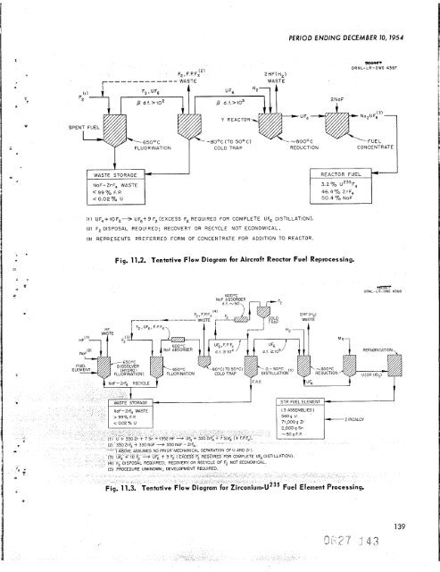
ANP QUARTERLY PROGRESS REPORT standpoint of both operational and corrosion prob- lems but is efficient and rapid in the high-tempera- liquid medium of fused fluoride salts. ircraft Reactor Fuels he recovery and reprocessing schedule for fluid-fuel aircraft reactors will probably be dictated by aircroft reactor and turbine maintenance sched- ules rather than by the rate of formation of neutron poisons. It is anticipated that operation will follow a schedule such as: (1) one day of oper- ation and one day of downtime for an accumulation n operatingdays, (2) seven days of downtime for minor maintenance, (3) repetition of this sched- ule until 1000 operating hours have been accumu- lated. After 1000 hr of operation, the entire reactor will be dumped and the fuel will be reprocessed. icipated cooling period before repro- II be 10 days to allow decay of short- activities. The minimum decontamination factor required for the process would be approxi- mately 100 for poison removal only. The other steps in fuel makeupcan easily be handled remotely. The following essential steps are used in the chemical processing (Fig. 11.2). First, the UF, in the molten fuel mixture is fluorinated to volatile UF, by introducing a 10-fold excess of elemental fluorine to achieve separation and partial decon- tamination from the other fuel components and fission products; second, the UF, is reduced to UF, with hydrogen in the gas phase in the Y reactor, as designed by K-25; and third, the re- sulting UF, is added to 2 moles of NaF to prepare a fuel concentrate for subsequent return to the reactor. Present knowledge of this system indicates that all steps are adaptable for radioactive remote operati on. Considerable engineering development and operational experience have been obtained with the second and third steps, while extended laboratory development has indicated the feasibility of the direct fluorination of the molten fuel mixture. geneous Reactor Fuels The separation of U235 from zirconium alloy fuel elements is currently the most promising application of the fluoride process to fixed fuel element reactors. The dissolution rate of zirconium with HF in the NaF-ZrF, fused salt is very high, that is, 22 to 35 milshr (Table 11.4). The range 138 probably due to metallurgical differences. Although the ratio of zirconium to uranium is very high in STR elements, the cost of HF to dissolve zirconium will be only 54 per gram of U235. A probable method for zirconium separation as a guide for process development is indicated by the flow diagram shown in Fig. 11.3. This flow sheet is similar to that for fluid-fuel processing, but it includes hydrofluorination of the fuel element in a TABLE 11.4. RATES OF HF PENETRATION OF VARIOUS METALS AND ALLOYS IN A TYPICAL FUSED FLUORIDE SALT BATH Bath composition: NaF-KF-ZrF, (7-48.5-44.5 mole %) HF flow rate: 3 250 cm /min Temperature: 675'C Nitrogen or argon blanket incases ofopen test vessels Material Vanadium Si I icon Nickel Monel Molybdenum Tungsten Silicon carbide Type 304 stainless steel Type 347 Nb stainless steel Niobium Tantalum Manganese Mild steel (Unistrut) 1 . Thorium, h-tn. plate Uranium Zirconium C hrom i um Titanium Zircaloy-2 95 wt % uranium-5 wt % zircon i urn Tin Zinc Penetration Rate (mi I s /h r) Not detected Not detected 0.0001 0.02 0.03 0.06 2* 4 7 7 8 10 13 14 17 22 to 35** 31 31 22 to 46** 50 Sampl e dissolved instantly Sample dissolved instantly *Material disintegrated and left suspended particles. **Range is due to metallurgical differences in indivi du a1 specimens. 1 *
NoF-ZrF, WASTE < 99 70 F. P. < 0.02% u -8OOC (TO 5OoC) COLD TRAP 2HF(H2) WASTE (1) UF,++OF2+ UF6t9 F2 (EXCESS F2 REQUIRED FOR COMPLETE UF6 DISTILLATION). (2) F2 DISPOSAL REQUIRED; RECOVERY OR RECYCLE NOT ECONOMICAL. (3) REPRESENTS PREFERRED FORM OF CONCENTRATE FOR ADDITION TO REACTOR. PERIOD ENDING DECEMBER 70, 7954 46.4qb ZrF, 50.4 '70 NoF Fig. 11.2. Tentative Flow Diagram for Aircraft Reactor Fuel Reprocessing. 6OO0C 80eC(T050pC) COMPLETE UF6 DISTILLATION) OT ECONOMICAL SEBnC? ORNL-LR-DWG 4387 C 0 N C E NTR ATE s m ORNL-LII-DWG 4388
- Page 100 and 101: ANP QUARTERLY PROGRESS REPORT Fig.
- Page 102 and 103: 06 dWnd lV'91NVH33W 01 A XI13 X3tlA
- Page 104 and 105: ANP QUARTERLY PROGRESS REPORT 0.001
- Page 106 and 107: I ANP QUARTERLY PROGRESS REPORT ] 1
- Page 108 and 109: ANP QUARTERLY PROGRESS REPORT If a
- Page 110 and 111: ANP QUARTERLY PROGRESS REPORT phase
- Page 112 and 113: ANP QUARTERLY PROGRESS REPORT 7. ME
- Page 114 and 115: ANP QUARTERLY PROGRESS REPORT fabri
- Page 116 and 117: ANP QUARTERLY PROGRESS REPORT - N -
- Page 118 and 119: ANP QUARTERLY PROGRESS REPORT Fig.
- Page 120 and 121: 1 I ANP QUARTERLY PROGRESS REPORT h
- Page 122 and 123: ANP QUARTERLY PROGRESS REPORT rruga
- Page 124 and 125: ANP QUARTERLY PROGRESS REPORT eat t
- Page 126 and 127: ANP QUARTERLY PROGRESS REPORT Plast
- Page 128 and 129: ANP QUARTERLY PROGRESS REPORT 0.2 0
- Page 130 and 131: ANP QUARTERLY PROGRESS REPORT STAIN
- Page 132 and 133: i ANP QUARTERLY PROGRESS REPORT The
- Page 134 and 135: ANP QUARTERLY PROGRESS REPORT Three
- Page 136 and 137: ANP QUARTERLY PROGRESS REPORT - ORN
- Page 138 and 139: ANP QUARTERLY PROGRESS REPORT kw at
- Page 140 and 141: ANP QUARTERLY PROGRESS REPORT felt
- Page 142 and 143: ANP QUARTERLY PROGRESS REPORT chlor
- Page 144 and 145: ANP QUARTERLY PROGRESS REPORT prese
- Page 146 and 147: ! ANP QUARTERLY PROGRESS REPORT 11.
- Page 148 and 149: ANP QUARTERLY PROGRESS REPORT 136 A
- Page 152 and 153: fused salt bath to permit dissoluti
- Page 154 and 155: Fr . F
- Page 156 and 157: ANP QUARlERlY PROGRESS REPORT chara
- Page 158 and 159: ANP QUARTERLY PROGRESS REPORT injur
- Page 160 and 161: ANP QUARTERLY PROGRESS REPORT 148 X
- Page 162 and 163: ANP QUARTERLY PROGRESS REPORT In co
- Page 164 and 165: ANP QUARTERLY PROGRESS REPORT - 103
- Page 166 and 167: ANP QUARTERLY PROGRESS REPORT condu
- Page 168 and 169: ANP QUARTERLY PROGRESS REPORT For m
- Page 170 and 171: 15. TOWER SHIELDING FACILITY C. E.
- Page 172 and 173: ANP QUARTERLY PROGRESS REPORT - .-
- Page 174 and 175: ANP QUARTERLY PROGRESS REPORT 162 -
- Page 176 and 177: h .e 0 c 0 L ’c v c t 0 W v) 0 a
- Page 178 and 179: f r e
NoF-ZrF, WASTE<br />
< 99 70 F. P.<br />
< 0.02% u<br />
-8OOC (TO 5OoC)<br />
COLD TRAP<br />
2HF(H2)<br />
WASTE<br />
(1) UF,++OF2+ UF6t9 F2 (EXCESS F2 REQUIRED FOR COMPLETE UF6 DISTILLATION).<br />
(2) F2 DISPOSAL REQUIRED; RECOVERY OR RECYCLE NOT ECONOMICAL.<br />
(3) REPRESENTS PREFERRED FORM OF CONCENTRATE FOR ADDITION TO REACTOR.<br />
PERIOD ENDING DECEMBER 70, 7954<br />
46.4qb ZrF,<br />
50.4 '70 NoF<br />
Fig. 11.2. Tentative Flow Diagram for Aircraft Reactor Fuel Reprocessing.<br />
6OO0C<br />
80eC(T050pC)<br />
COMPLETE UF6 DISTILLATION)<br />
OT ECONOMICAL<br />
SEBnC?<br />
<strong>ORNL</strong>-LR-DWG 4387<br />
C 0 N C E NTR ATE<br />
s m<br />
<strong>ORNL</strong>-LII-DWG 4388


