

ORNL-1816 - the Molten Salt Energy Technologies Web Site
ORNL-1816 - the Molten Salt Energy Technologies Web Site
ORNL-1816 - the Molten Salt Energy Technologies Web Site

You also want an ePaper? Increase the reach of your titles
YUMPU automatically turns print PDFs into web optimized ePapers that Google loves.
ANP QUARTERLY PROGRESS REPORT<br />
standpoint of both operational and corrosion prob-<br />
lems but is efficient and rapid in <strong>the</strong> high-tempera-<br />
liquid medium of fused fluoride salts.<br />
ircraft Reactor Fuels<br />
he recovery and reprocessing schedule for<br />
fluid-fuel aircraft reactors will probably be dictated<br />
by aircroft reactor and turbine maintenance sched-<br />
ules ra<strong>the</strong>r than by <strong>the</strong> rate of formation of neutron<br />
poisons. It is anticipated that operation will<br />
follow a schedule such as: (1) one day of oper-<br />
ation and one day of downtime for an accumulation<br />
n operatingdays, (2) seven days of downtime<br />
for minor maintenance, (3) repetition of this sched-<br />
ule until 1000 operating hours have been accumu-<br />
lated. After 1000 hr of operation, <strong>the</strong> entire reactor<br />
will be dumped and <strong>the</strong> fuel will be reprocessed.<br />
icipated cooling period before repro-<br />
II be 10 days to allow decay of short-<br />
activities. The minimum decontamination<br />
factor required for <strong>the</strong> process would be approxi-<br />
mately 100 for poison removal only. The o<strong>the</strong>r<br />
steps in fuel makeupcan easily be handled remotely.<br />
The following essential steps are used in <strong>the</strong><br />
chemical processing (Fig. 11.2). First, <strong>the</strong> UF,<br />
in <strong>the</strong> molten fuel mixture is fluorinated to volatile<br />
UF, by introducing a 10-fold excess of elemental<br />
fluorine to achieve separation and partial decon-<br />
tamination from <strong>the</strong> o<strong>the</strong>r fuel components and<br />
fission products; second, <strong>the</strong> UF, is reduced to<br />
UF, with hydrogen in <strong>the</strong> gas phase in <strong>the</strong> Y<br />
reactor, as designed by K-25; and third, <strong>the</strong> re-<br />
sulting UF, is added to 2 moles of NaF to prepare<br />
a fuel concentrate for subsequent return to <strong>the</strong><br />
reactor. Present knowledge of this system indicates<br />
that all steps are adaptable for radioactive remote<br />
operati on. Considerable engineering development<br />
and operational experience have been obtained<br />
with <strong>the</strong> second and third steps, while extended<br />
laboratory development has indicated <strong>the</strong> feasibility<br />
of <strong>the</strong> direct fluorination of <strong>the</strong> molten fuel mixture.<br />
geneous Reactor Fuels<br />
The separation of U235 from zirconium alloy<br />
fuel elements is currently <strong>the</strong> most promising<br />
application of <strong>the</strong> fluoride process to fixed fuel<br />
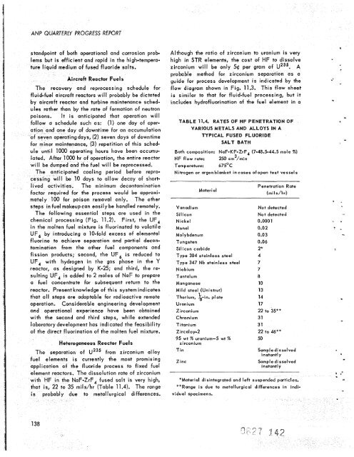
element reactors. The dissolution rate of zirconium<br />
with HF in <strong>the</strong> NaF-ZrF, fused salt is very high,<br />
that is, 22 to 35 milshr (Table 11.4). The range<br />
138<br />
probably due to metallurgical differences.<br />
Although <strong>the</strong> ratio of zirconium to uranium is very<br />
high in STR elements, <strong>the</strong> cost of HF to dissolve<br />
zirconium will be only 54 per gram of U235. A<br />
probable method for zirconium separation as a<br />
guide for process development is indicated by <strong>the</strong><br />
flow diagram shown in Fig. 11.3. This flow sheet<br />
is similar to that for fluid-fuel processing, but it<br />
includes hydrofluorination of <strong>the</strong> fuel element in a<br />
TABLE 11.4. RATES OF HF PENETRATION OF<br />
VARIOUS METALS AND ALLOYS IN A<br />
TYPICAL FUSED FLUORIDE<br />
SALT BATH<br />
Bath composition: NaF-KF-ZrF, (7-48.5-44.5 mole %)<br />
HF flow rate:<br />
3<br />
250 cm /min<br />
Temperature: 675'C<br />
Nitrogen or argon blanket incases ofopen test vessels<br />
Material<br />
Vanadium<br />
Si I icon<br />
Nickel<br />
Monel<br />
Molybdenum<br />
Tungsten<br />
Silicon carbide<br />
Type 304 stainless steel<br />
Type 347 Nb stainless steel<br />
Niobium<br />
Tantalum<br />
Manganese<br />
Mild steel (Unistrut)<br />
1 .<br />
Thorium, h-tn. plate<br />
Uranium<br />
Zirconium<br />
C hrom i um<br />
Titanium<br />
Zircaloy-2<br />
95 wt % uranium-5 wt %<br />
zircon i urn<br />
Tin<br />
Zinc<br />
Penetration Rate<br />
(mi I s /h r)<br />
Not detected<br />
Not detected<br />
0.0001<br />
0.02<br />
0.03<br />
0.06<br />
2*<br />
4<br />
7<br />
7<br />
8<br />
10<br />
13<br />
14<br />
17<br />
22 to 35**<br />
31<br />
31<br />
22 to 46**<br />
50<br />
Sampl e dissolved<br />
instantly<br />
Sample dissolved<br />
instantly<br />
*Material disintegrated and left suspended particles.<br />
**Range is due to metallurgical differences in indivi<br />
du a1 specimens.<br />
1<br />
*
![Review of Molten Salt Reactor Physics Calculations [Disc 2]](https://img.yumpu.com/21979492/1/190x247/review-of-molten-salt-reactor-physics-calculations-disc-2.jpg?quality=85)


