ORNL-1816 - the Molten Salt Energy Technologies Web Site
ORNL-1816 - the Molten Salt Energy Technologies Web Site ORNL-1816 - the Molten Salt Energy Technologies Web Site
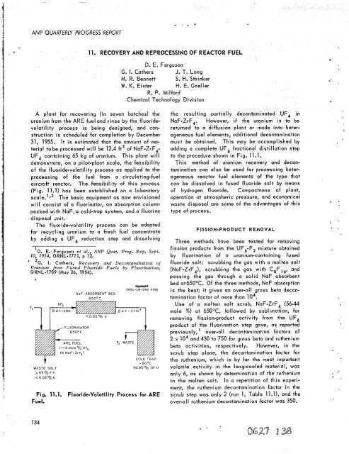
! ANP QUARTERLY PROGRESS REPORT 11. RECOVERYANDREPROCESSINGOFREACTOR FUEL G. I. Cathers M. R. Bennett W. K. Eister A plant for recovering (in seven batches) the uranium from the ARE fuel and rinse by the fluoride- volatility process is being designed, and con- struction is scheduled for completion by December 31, 1955. It is estimated that the amount of ma- terial to be processed will be 12.4 ft3 of NaF-ZrF,- UF, containing 65 kg of uranium, This plant will demonstrate, on a pilot-plant scale, the feasibility of the fluoride-volatility process as applied to the processing of the fuel from a circulating-fuel aircraft reactor. The feasibility of this process (Fig. 11.1) has been established on a laboratory scale.’*2 The basic equipment as now envisioned will consist of a fluorinator, an absorption column packed with NaF, a cold-trap system, and a fluorine disposal dnit. The fluoride-volatil ity process can be adapted for recycling uranium to a fresh fuel concentrate by adding a UF, reduction step and dissolving I D. E. Ferguson et al., ANP Quar. Prog. Rep. Sept. IO, 1954, ORNL-1771, p 12. * 2G. 1. Cathers, Recovery and Decontamination of Uranium from Fused Fluoride Fuels by Fluorination, ORNL-1709 (May 26, 1954). I WASTE SALT > 999b F P
3 - Z . * c * i PERIOD ENDING DECEMBER 10,7954 TABLE 11.1. DECONTAMINATION OBTAINED IN THE FLUORIDE-VOLATILITY PROCESS BY SCRUBBING UF6 Synthetic ARE fuel, prepared by hydrofluorination of 6 g of irradiated uranium metal in 67 g of NaF-ZrF4 (56-44 mole X), fluorinated at 65OoC with 40- to 80-fold excess fluorine. Run 1: UF6 product plus excess fluorine passed through 67 g of molten NaF-ZrF4 at 65OoC into a dry-ice trap and then resublimed into second trap. Runs 2 and 3: UF, product separated from excess fluorine in dry-ice trap and then volatilized through a C8Fl, still into a second trap. Beta Decontami nati on Factors Activity Run 1 Run 2 Run 3 Over-al I Scrub* Over-a1 I Scrub* Over-al I Scrub* Gross 4800 2.7 290 Ru 350 2.3 16 Zr 3.2 lo4 6.8 x lo4 Nb 1800 47 1200 1.2 250 2.2 14 4.7 lo4 TRE 2 x 10⁶ 2 x 10, 2 105 *Decontamination factor calculated for scrub step alone on basis of activity extracted from scrub material. Scrubbing the UF, product from the fluorination and sublimation steps with fluorocarbon (C,Fl,) did not improve the decontamination (runs 2 and 3, Table 11.1). Approximately 9 g of UF, sublimed from a fluorination run, was passed into the bottom of a C,F, distillation column (0.5 in. in diameter by 14 in. high, packed with t2-in. nickel Fenske helices) that was operating at full reflux at about gas had to be refluorinated from the NaF bed at 65OOC before being trapped. However, the gross decon- 86 tamination factors in the two fractions were of the same order, that is, 2 x lo3. The uranium loss on the NaF was only 0.01%. Two experiments were then performed with 30-9 beds of 20- to 40-mesh NaF held at 65OOC to eliminate the refluorination step (runs 2 and 3, Table 11.2). The results in both tests showed high absorption of ruthenium and niobium beta activities, and the over-till gross 4 beta decontamination factor was greater than 10 . eral, 1 to 10% of Nearly all the niobium activity was accounted for in the reactor and fused salt, while 7555 of the
- Page 96 and 97: ANP QUARTERLY PROGRESS REPORT appea
- Page 98 and 99: 1 I I I . . ANP QUARTERLY PROGRESS
- Page 100 and 101: ANP QUARTERLY PROGRESS REPORT Fig.
- Page 102 and 103: 06 dWnd lV'91NVH33W 01 A XI13 X3tlA
- Page 104 and 105: ANP QUARTERLY PROGRESS REPORT 0.001
- Page 106 and 107: I ANP QUARTERLY PROGRESS REPORT ] 1
- Page 108 and 109: ANP QUARTERLY PROGRESS REPORT If a
- Page 110 and 111: ANP QUARTERLY PROGRESS REPORT phase
- Page 112 and 113: ANP QUARTERLY PROGRESS REPORT 7. ME
- Page 114 and 115: ANP QUARTERLY PROGRESS REPORT fabri
- Page 116 and 117: ANP QUARTERLY PROGRESS REPORT - N -
- Page 118 and 119: ANP QUARTERLY PROGRESS REPORT Fig.
- Page 120 and 121: 1 I ANP QUARTERLY PROGRESS REPORT h
- Page 122 and 123: ANP QUARTERLY PROGRESS REPORT rruga
- Page 124 and 125: ANP QUARTERLY PROGRESS REPORT eat t
- Page 126 and 127: ANP QUARTERLY PROGRESS REPORT Plast
- Page 128 and 129: ANP QUARTERLY PROGRESS REPORT 0.2 0
- Page 130 and 131: ANP QUARTERLY PROGRESS REPORT STAIN
- Page 132 and 133: i ANP QUARTERLY PROGRESS REPORT The
- Page 134 and 135: ANP QUARTERLY PROGRESS REPORT Three
- Page 136 and 137: ANP QUARTERLY PROGRESS REPORT - ORN
- Page 138 and 139: ANP QUARTERLY PROGRESS REPORT kw at
- Page 140 and 141: ANP QUARTERLY PROGRESS REPORT felt
- Page 142 and 143: ANP QUARTERLY PROGRESS REPORT chlor
- Page 144 and 145: ANP QUARTERLY PROGRESS REPORT prese
- Page 148 and 149: ANP QUARTERLY PROGRESS REPORT 136 A
- Page 150 and 151: ANP QUARTERLY PROGRESS REPORT stand
- Page 152 and 153: fused salt bath to permit dissoluti
- Page 154 and 155: Fr . F
- Page 156 and 157: ANP QUARlERlY PROGRESS REPORT chara
- Page 158 and 159: ANP QUARTERLY PROGRESS REPORT injur
- Page 160 and 161: ANP QUARTERLY PROGRESS REPORT 148 X
- Page 162 and 163: ANP QUARTERLY PROGRESS REPORT In co
- Page 164 and 165: ANP QUARTERLY PROGRESS REPORT - 103
- Page 166 and 167: ANP QUARTERLY PROGRESS REPORT condu
- Page 168 and 169: ANP QUARTERLY PROGRESS REPORT For m
- Page 170 and 171: 15. TOWER SHIELDING FACILITY C. E.
- Page 172 and 173: ANP QUARTERLY PROGRESS REPORT - .-
- Page 174 and 175: ANP QUARTERLY PROGRESS REPORT 162 -
- Page 176 and 177: h .e 0 c 0 L ’c v c t 0 W v) 0 a
- Page 178 and 179: f r e
!<br />
ANP QUARTERLY PROGRESS REPORT<br />
11. RECOVERYANDREPROCESSINGOFREACTOR FUEL<br />
G. I. Ca<strong>the</strong>rs<br />
M. R. Bennett<br />
W. K. Eister<br />
A plant for recovering (in seven batches) <strong>the</strong><br />
uranium from <strong>the</strong> ARE fuel and rinse by <strong>the</strong> fluoride-<br />
volatility process is being designed, and con-<br />
struction is scheduled for completion by December<br />
31, 1955. It is estimated that <strong>the</strong> amount of ma-<br />
terial to be processed will be 12.4 ft3 of NaF-ZrF,-<br />
UF, containing 65 kg of uranium, This plant will<br />
demonstrate, on a pilot-plant scale, <strong>the</strong> feasibility<br />
of <strong>the</strong> fluoride-volatility process as applied to <strong>the</strong><br />
processing of <strong>the</strong> fuel from a circulating-fuel<br />
aircraft reactor. The feasibility of this process<br />
(Fig. 11.1) has been established on a laboratory<br />
scale.’*2 The basic equipment as now envisioned<br />
will consist of a fluorinator, an absorption column<br />
packed with NaF, a cold-trap system, and a fluorine<br />
disposal dnit.<br />
The fluoride-volatil ity process can be adapted<br />
for recycling uranium to a fresh fuel concentrate<br />
by adding a UF, reduction step and dissolving<br />
I D. E. Ferguson et al., ANP Quar. Prog. Rep. Sept.<br />
IO, 1954, <strong>ORNL</strong>-1771, p 12.<br />
* 2G. 1. Ca<strong>the</strong>rs, Recovery and Decontamination of<br />
Uranium from Fused Fluoride Fuels by Fluorination,<br />
<strong>ORNL</strong>-1709 (May 26, 1954).<br />
I<br />
WASTE SALT<br />
> 999b F P<br />


