

ORNL-1771 - Oak Ridge National Laboratory
ORNL-1771 - Oak Ridge National Laboratory
ORNL-1771 - Oak Ridge National Laboratory

You also want an ePaper? Increase the reach of your titles
YUMPU automatically turns print PDFs into web optimized ePapers that Google loves.
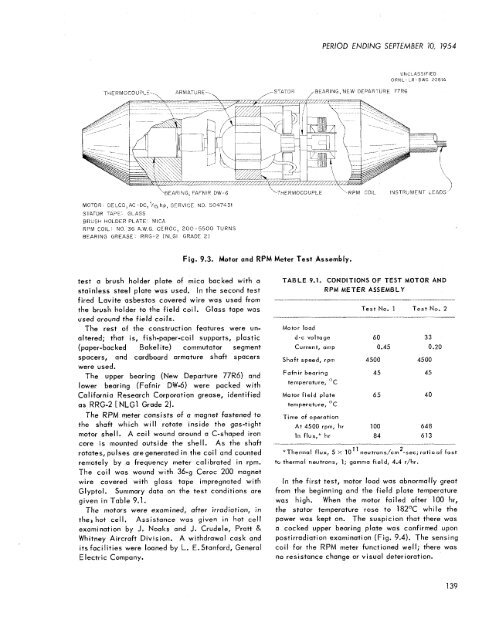
MOTOR<br />
SlATOR TAPE GLASS<br />
BRUSH HOLDER PLATE MICA<br />
PERIOD ENDING SEPTEMBER IO, 7954<br />
UNCLASSIFIED<br />
<strong>ORNL</strong>-1.R-DWG 20814<br />
'HFARING, FAFNIR DVJ-6 \THERMOCOUPLE RPM COIL 'NSTRUMFNT LEADS '<br />
DELCO,AC-DC, '115 hp, SFRVICE NO 5047431<br />
RPM COIL NO 36 A W G CCROC, 200-5500 TURNS<br />
BFARING GREASE RRG-2 (NL.GI GRADE 2)<br />
test a brush holder plate of mica backed with a<br />
stainless steel plate was used, In the second test<br />
fired Lavite asbestos covered wire was used from<br />
the brush holder to the field coil. Glass tape was<br />
used around the field coils.<br />
The rest of the construction features were un-<br />
altered; that is, fish-paper-coil supports, plastic<br />
(paper-backed Bake1 ite) commutator segment<br />
spacers, and cardboard armature shaft spacers<br />
were used.<br />
The upper bearing (New Departure 77R6) and<br />
lower bearing (Fafnir DW-6) were packed with<br />
California Research Corporation grease, identified<br />
as RRG-2 [NLGl Grade 21.<br />
The RPM meter consists of a magnet fastened to<br />
the shaft which will rotate inside the gas-tight<br />
motor shell. A coil wound around a C-shaped iron<br />
core is mounted outside the shell. As the shaft<br />
rotates, pulses aregenerated in the coil and counted<br />
remotely by a frequency meter calibrated in rprn.<br />
The coil was wound with 36-9 Ceroc 200 magnet<br />
wire covered with glass tape impregnated with<br />
Glyptol. Summary data on the test conditions are<br />
given in Table 9.1.<br />
The motors were examined, after irradiation, in<br />
the* hot cell. Assistance was given in hot cell<br />
examination by J. Noaks and J. Crudele, Pratt &<br />
Whitney Aircraft Division. A withdrawal cask and<br />
its facilities were loaned by L. E.Stanford, General<br />
Electric Company.<br />
Fig. 9.3. Motor and RPM Meter Test Assembly.<br />
TABLE 9.1. CONDITIONS OF TEST MOTOR AND<br />
RPM METER ASSEMBLY<br />
Motor load<br />
Test No. 1 Test No. 2<br />
d-c voltage 60 33<br />
Current, amp 0.45 0.20<br />
Shaft speed, rprn 4500 4500<br />
Fufnir bearing<br />
temperature, 'C<br />
45 45<br />
Motor field plate<br />
temperature, OC<br />
65 40<br />
Time of operation<br />
At 4500 rprn, hr 100 648<br />
In flux,* hr 84 613<br />
*Thermal flux, 5 x 10" neu+rons/cm2-sec; ratio of fast<br />
to thermal neutrons, 1; gumma field, 4.4 r/hr.<br />
In the first test, motor load was abnormally great<br />
from the beginning and the field plate temperature<br />
was high. When the motor failed after 100 hr,<br />
the stator temperature rose to 182OC while the<br />
power was kept on. The suspicion that there was<br />
a cocked upper bearing plate was confirmed upon<br />
postirradiation examination (Fig. 9.4). The sensing<br />
coil for the RPM meter functioned well; there was<br />
no resistance change or visual deterioration.<br />
139
![Review of Molten Salt Reactor Physics Calculations [Disc 2]](https://img.yumpu.com/21979492/1/190x247/review-of-molten-salt-reactor-physics-calculations-disc-2.jpg?quality=85)


