

ORNL-2106 - the Molten Salt Energy Technologies Web Site
ORNL-2106 - the Molten Salt Energy Technologies Web Site
ORNL-2106 - the Molten Salt Energy Technologies Web Site

Create successful ePaper yourself
Turn your PDF publications into a flip-book with our unique Google optimized e-Paper software.
ANP PROJECT PROGRESS REPORT<br />
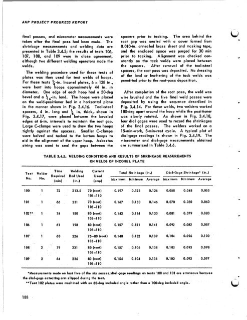
final passes, and micrometer measurements were<br />
taken after <strong>the</strong> final pass had been made. The<br />
shrinkage measurements and welding data are<br />
presented in Table 3.4.5; <strong>the</strong> results of tests la,<br />
107, 108, and 109 were in close agreement,<br />
although two different welding operators made <strong>the</strong><br />
welds.<br />
The welding procedure used for <strong>the</strong>se tests of<br />
plates was <strong>the</strong>n used for test welds of hoops.<br />
For <strong>the</strong>se tests ?' . lnconel plates, 6 x 138 in.,<br />
were bent into tin oops approximately 44 in. in<br />
diameter. One edge of each hoop had a 50-deg<br />
bevel and a t6-in. land. The hoops were placed<br />
on <strong>the</strong> weld-positioner bed in a horizontal plane<br />
in <strong>the</strong> manner shown in Fig. 3.4.16. Tool-steel<br />
spacers, 4 in. long and \ in. thick,-shown in<br />
Fig. 3.4.17, were placed between <strong>the</strong> beveled<br />
edges at 6-in. intervals to maintain <strong>the</strong> root gap.<br />
Large C-clamps were used to draw <strong>the</strong> two hoops<br />
tightly against <strong>the</strong> spacers. Smaller C-clamps<br />
were halved and tacked to <strong>the</strong> bottom hoops to<br />
aid in <strong>the</strong> alignment of <strong>the</strong> upper hoop. Asbestos<br />
string was used to seal <strong>the</strong> gaps between <strong>the</strong><br />
spacers prior to tacking. The area behind <strong>the</strong><br />
root gap was sealed with a cover formed from<br />
0.010-in. annealed brass sheet and masking tape,<br />
and <strong>the</strong> enclosed space was purged for 30 min<br />
prior to tacking, Alignment was checked con- -<br />
stantly as -<strong>the</strong> tack welds were placed between<br />
<strong>the</strong> spacers. After removal of <strong>the</strong> tool-steel<br />
spacers, <strong>the</strong> root pass was deposited. No dressing<br />
of <strong>the</strong> land or fea<strong>the</strong>ring of <strong>the</strong> tack welds was<br />
permitted prior to <strong>the</strong> root-pass deposition.<br />
After completion of <strong>the</strong> root pass, <strong>the</strong> weld was<br />
wire brushed and <strong>the</strong> five final weld passes were<br />
deposited by using <strong>the</strong> sequence described in<br />
Fig. 3.4.14. For <strong>the</strong>se welds, two welders worked<br />
180-deg apart around <strong>the</strong> hoop while <strong>the</strong> positioner<br />
was slowly rotated. As shown in Fig. 3.4.18,<br />
four dial gages were used to record <strong>the</strong> shrinkages<br />
of <strong>the</strong> final passes. The welders worked on a<br />
15-min-work, 5-min-rest cycle. A typical plot of<br />
dial-gage readings is shown in Fig. 3.4.19. The<br />
micrometer and dial-gage measurements obtained<br />
are summarized in Table 3.4.6.<br />
TABLE 3.45. WELDING CONDITIONS AND RESULTS OF SHRINKAGE MEASUREMENTS<br />
ON WELDS OF INCONEL PLATE<br />
Test Welder Time Welding Current Total Shrinkage (in,) Diol-Gage Shrinkage' (in.)<br />
No. No.<br />
Required<br />
(min)<br />
Rad Used<br />
(in.)<br />
Used<br />
(amp)<br />
Maximum Minimum Average Maximum Minimum Average<br />
100 1<br />
101 1<br />
102t' 1<br />
106 1<br />
107 1<br />
108 2<br />
109 2<br />
72<br />
66<br />
74<br />
61<br />
60<br />
79<br />
64<br />
213.5 70 (root) 0.1 97<br />
105-110<br />
231 70 (root) 0.1 67<br />
1 05-1 10<br />
180 80 (root) 0.1 42<br />
105-110<br />
198 80 (root) 0.157<br />
105-1 10<br />
226 75-80 (root) 0.148<br />
105-1 10<br />
231 80 (root) 0.157<br />
1 05- 1 1 0<br />
236 80 (root) 0.1 54<br />
105-1 10<br />
0.123 0.126 0.058 0.048<br />
0.130 0.146 0.070 0.050<br />
0.114 0.130 0.081 0.079<br />
0.121 0.141 0.092 0.082<br />
0.132 0.139 0.104 0.096<br />
0.106 0.138 0.103 0.093<br />
0.104 0.136 0.102 0.092<br />
*Measurements made on last five of <strong>the</strong> six passes;dial-goge readings on tests 100 and 101 are erroneous because<br />
<strong>the</strong> dial-gage actuating arm slipped during <strong>the</strong> test.<br />
188<br />
**Test 102 plates were machined with an 80-deg included angle ra<strong>the</strong>r thon a 100-deg included angle.<br />
0.053<br />
0.060<br />
0.080<br />
0.087<br />
0.1 00<br />
0.098<br />
0.097<br />
s<br />
.<br />
c<br />
*
![Review of Molten Salt Reactor Physics Calculations [Disc 2]](https://img.yumpu.com/21979492/1/190x247/review-of-molten-salt-reactor-physics-calculations-disc-2.jpg?quality=85)


