ORNL-2106 - the Molten Salt Energy Technologies Web Site
ORNL-2106 - the Molten Salt Energy Technologies Web Site ORNL-2106 - the Molten Salt Energy Technologies Web Site
ANP PROJECT PROGRESS REPORT SECTION A-A circuit^,^ and flow tests with water being pumped by the two fuel pumps under simulated reactor flow conditions are under way. Twin fuel pump operation has been demonstrated up to 3000 rpm, although 2400 rpm produced approxi- mately rated conditions of head and flow. De- gassing of the system with pump speeds of 2400 rpm required less than 30 sec with the water level 1 in. or more above the bottom of the surge chamber. When the speeds of both pumps were lowered in unison from 2400 rpm, the first signs of ingassing 3D. R. Ward, ANP Qwr. Prog. Rep. Dec. 10, 1955, ORNL-2012, p 65, Fig. 2.29. 24 Fig. 1.1.6. Sodium Expansion Tank Design. occurred at 1200 rpm. The amount of gas entrained during operation with the pump speeds matched was believed to have reached a maximum, not exceeding 0.1 vol %, at 500 rpm. At speed levels above 1200 rpm, ingassing could not be detected with mismatching of up to 5%. Mismatching the speeds by 20% produced ingassing estimated to be 0.5 vol %. When the power to one of the hy- draulically driven fuel pumps was cut off while both pumps were running uniformly at 2400 rpm, about 13 sec was required for the one pump to stop. This one-pump-stopped condition created a. ingassing of roughly 2 vol %. 6.i . a
SOD,UM r--- INCONEL TANK ROOF 0 0.5 1 .o 1.5 2.0 UNCLASSIFIED ORNL-LR-DWG (4949 DISTANCE FROM BOTTOM SURFACE OF ROOF (Cm) Fig. 1.1.7. Energy Deposition in Sodium Ex- pansion Tank Roof Due to Gamma Radiation. Surging and instability were noted in pump speeds, flow rates, pumping power, and inlet and discharge pressures centrifuge hardware served instabitity. include the addition of baffles, a reduction in PERlOD ENDING JUNE 10, 1956 bypass flow rates, and a redesign of the passages from the pumps to the surge chamber. CORE FLOW STUDIES W. T. Furgerson W. J. Stelzman D. 8. Trauger Changes in design of both the center volute of the axial-flow type of header and the island expansion bellows located within the header of the proposed ART core resulted in an unsatisfactory core flow pattern being generated by the previously satisfactory inlet guide vane, designated GS-2, and the conical baffle plate, designated GS-2- P3 (ref. 4). Under the revised design, this particular guide vane and baffle plate combination generated flow reversal at the island surface in the region of the equator. Systematic relocation of the conical baffle plate only and analysis of the resulting core flow pattern yielded baffle plate GS-2-Pl0, which, in combination with guide vane GS-2, again generated a flow pattern containing no flow reversal along either the outer core shell or the island surfaces. Brief periods of minor flow reversals did occur at the equator; however, these occurred in midstream and seemed to be caused by the turbulent condition of the fluid mass in this region, In general, the flow generated in the upper half of the core by this cbmbination was extremely unstable, but it exhibited excellent surface scrubbing, with very good transfer of fluid from the walls,and excellent fluid niixing. Below the equator, some improvements were noted in the fluid flow properties; however, the streamlines again tended to hug the inner and outer surfaces as they approached the core outlet. Attempts had previously been made with the original axial-flow header to improve the flow in the lower half of the core by means of turbulators on the island mediately below the guide vanes and the shell surface immediately below e equator; however, the improvement was only nor. This latest design is being evaluated in the half-scale ART volumeheat-source apparatus sfer and Physical .L 4G. D. Whitrnon, W. J. Stelzrnan, and W. T. Furgcrson, ANP Quar. Prog. Rep. March 10. 1955, ORNL-2061, p 24. 25
- Page 3 and 4: Part 1 AIRCRAFT REACTOR ENGINEERING
- Page 5 and 6: STATUS OF ART DESIGN Design work on
- Page 7 and 8: of pressure loads. The idealized mo
- Page 9: UPPER DECK 7 @ PRESSURE SHEL PERIOD
- Page 13 and 14: TABLE 1.1.1. NaK PUMP SPEEDS AND HO
- Page 15 and 16: 62 CALCULATED HEATING (w/crn3) N w
- Page 17 and 18: where I = radius of source (taken a
- Page 19 and 20: heat exchanger was used. The heatin
- Page 21 and 22: head which are bounded by various t
- Page 23 and 24: h bd * W - EcBRc+ ORNL-LR-DWG I4918
- Page 25 and 26: PERIOD ENDlNC JUNE 10. 1956 TABLE 1
- Page 27 and 28: ENRICHER ACTUATOR J. M. Eastman Spe
- Page 29 and 30: hd - Thus, even with an input signa
- Page 31 and 32: - . 140 120 p 100 g d 80 8 L s In y
- Page 33 and 34: and lose their hardness in the pres
- Page 35 and 36: p. W 2.5 0.5 0 400 OPERATING TIME (
- Page 37 and 38: i 20 too 80 40 20 PERIOD ENDING JUN
- Page 39 and 40: c' I - + r 500 450 400 3 50 300 2 2
- Page 41 and 42: 01) 0V3H 5: N 0 2 s 0 0 0 5: 0 2 s
- Page 43 and 44: the first 200OF and B0F/sec for the
- Page 45 and 46: PERIOD ENDING JUNE 10, 1956 TABLE 1
- Page 47 and 48: L 0 _, I, -* t; - PERIOD ENDING JUN
- Page 49 and 50: LJ 0.005 in. on the diameter and a
- Page 51 and 52: I 3 -I W CALROD HEATER 1500 I 1400
- Page 53 and 54: -17 Inconel I .._I_ I" .. _ _ ~ ._
- Page 55 and 56: i E ART FACILITY F. R. McQuilkin Co
- Page 57 and 58: L7i PERIOD ENDING JUNE 10, 1956 Fig
- Page 59 and 60: PERIOD ENDING JUNE 10, 1956 Fig. 1.
SOD,UM r--- INCONEL TANK ROOF<br />
0 0.5 1 .o 1.5 2.0<br />
UNCLASSIFIED<br />
<strong>ORNL</strong>-LR-DWG (4949<br />
DISTANCE FROM BOTTOM SURFACE OF ROOF (Cm)<br />
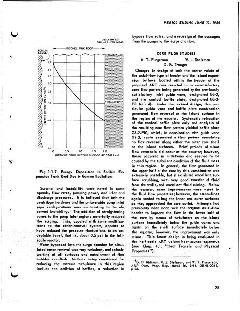
Fig. 1.1.7. <strong>Energy</strong> Deposition in Sodium Ex-<br />
pansion Tank Roof Due to Gamma Radiation.<br />
Surging and instability were noted in pump<br />
speeds, flow rates, pumping power, and inlet and<br />
discharge pressures<br />
centrifuge hardware<br />
served instabitity.<br />
include <strong>the</strong> addition of baffles, a reduction in<br />
PERlOD ENDING JUNE 10, 1956<br />
bypass flow rates, and a redesign of <strong>the</strong> passages<br />
from <strong>the</strong> pumps to <strong>the</strong> surge chamber.<br />
CORE FLOW STUDIES<br />
W. T. Furgerson W. J. Stelzman<br />
D. 8. Trauger<br />
Changes in design of both <strong>the</strong> center volute of<br />
<strong>the</strong> axial-flow type of header and <strong>the</strong> island expansion<br />
bellows located within <strong>the</strong> header of <strong>the</strong><br />
proposed ART core resulted in an unsatisfactory<br />
core flow pattern being generated by <strong>the</strong> previously<br />
satisfactory inlet guide vane, designated GS-2,<br />
and <strong>the</strong> conical baffle plate, designated GS-2-<br />
P3 (ref. 4). Under <strong>the</strong> revised design, this particular<br />
guide vane and baffle plate combination<br />
generated flow reversal at <strong>the</strong> island surface in<br />
<strong>the</strong> region of <strong>the</strong> equator. Systematic relocation<br />
of <strong>the</strong> conical baffle plate only and analysis of<br />
<strong>the</strong> resulting core flow pattern yielded baffle plate<br />
GS-2-Pl0, which, in combination with guide vane<br />
GS-2, again generated a flow pattern containing<br />
no flow reversal along ei<strong>the</strong>r <strong>the</strong> outer core shell<br />
or <strong>the</strong> island surfaces. Brief periods of minor<br />
flow reversals did occur at <strong>the</strong> equator; however,<br />
<strong>the</strong>se occurred in midstream and seemed to be<br />
caused by <strong>the</strong> turbulent condition of <strong>the</strong> fluid mass<br />
in this region, In general, <strong>the</strong> flow generated in<br />
<strong>the</strong> upper half of <strong>the</strong> core by this cbmbination was<br />
extremely unstable, but it exhibited excellent surface<br />
scrubbing, with very good transfer of fluid<br />
from <strong>the</strong> walls,and excellent fluid niixing. Below<br />
<strong>the</strong> equator, some improvements were noted in<br />
<strong>the</strong> fluid flow properties; however, <strong>the</strong> streamlines<br />
again tended to hug <strong>the</strong> inner and outer surfaces<br />
as <strong>the</strong>y approached <strong>the</strong> core outlet. Attempts had<br />
previously been made with <strong>the</strong> original axial-flow<br />
header to improve <strong>the</strong> flow in <strong>the</strong> lower half of<br />
<strong>the</strong> core by means of turbulators on <strong>the</strong> island<br />
mediately below <strong>the</strong> guide vanes and<br />
<strong>the</strong> shell surface immediately below<br />
e equator; however, <strong>the</strong> improvement was only<br />
nor. This latest design is being evaluated in<br />
<strong>the</strong> half-scale ART volumeheat-source apparatus<br />
sfer and Physical .L<br />
4G. D. Whitrnon, W. J. Stelzrnan, and W. T. Furgcrson,<br />
ANP Quar. Prog. Rep. March 10. 1955, <strong>ORNL</strong>-2061,<br />
p 24.<br />
25


