PSAS Avionics System Design Project - Portland State Aerospace ...
PSAS Avionics System Design Project - Portland State Aerospace ...
PSAS Avionics System Design Project - Portland State Aerospace ...

Create successful ePaper yourself
Turn your PDF publications into a flip-book with our unique Google optimized e-Paper software.
<strong>PSAS</strong> <strong>Avionics</strong> <strong>System</strong> <strong>Design</strong> <strong>Project</strong><br />
Michael Kennan Matt McFadden
<strong>PSAS</strong> <strong>Avionics</strong> <strong>System</strong> <strong>Design</strong> <strong>Project</strong><br />
Spring 1999<br />
Revision 3.1<br />
Michael Kennan<br />
Matt McFadden<br />
Faculty Advisor: Dr. Lee Casperson<br />
Industry Advisor: Andrew Greenberg
Acknowledgements<br />
This project is presented in partial fulfillment of the authors Senior <strong>Project</strong><br />
requirements for the Electrical and Computer Engineering Department at <strong>Portland</strong><br />
<strong>State</strong> University. We would like to thank our Faculty Advisor Dr. Lee Casperson and<br />
our Industry Advisor Andrew Greenberg for their assistance, guidance, and support<br />
throughout the course of the project.<br />
AESS <strong>Avionics</strong> <strong>System</strong> <strong>Design</strong> <strong>Project</strong> – Rev. 3.1 – Page 1
Abstract<br />
To meet the goal of developing an Inertial Navigation <strong>System</strong> for future rocket flights,<br />
the <strong>Portland</strong> <strong>State</strong> <strong>Aerospace</strong> Society (<strong>PSAS</strong>) requires a testbed system for<br />
developing, characterizing, and qualifying sensor and control packages. The system<br />
is required to be scalable and modular while meeting weight constraints and<br />
environmental standards such as force and temperature tolerance.<br />
This document provides an overview of previous amateur rocketry research<br />
performed by the <strong>PSAS</strong> and describes the authors’ design of a robust, scalable, and<br />
evolvable rocket avionics architecture. Emphasis is made on modularity, redundancy<br />
of critical hardware and software mechanisms, testability, and the maintenance of an<br />
open architecture to accommodate future changes to the system.<br />
This is a living document that represents a work in progress. Revisions will continue<br />
to be made throughout the development of the LV2 rocket project.<br />
AESS <strong>Avionics</strong> <strong>System</strong> <strong>Design</strong> <strong>Project</strong> – Rev. 3.1 – Page 2
Table of Contents<br />
ACKNOWLEDGEMENTS ......................................................................................................................... 1<br />
ABSTRACT................................................................................................................................................... 2<br />
TABLE OF CONTENTS ............................................................................................................................. 3<br />
TABLE OF FIGURES.................................................................................................................................. 5<br />
REVISIONS .................................................................................................................................................. 6<br />
INTRODUCTION ........................................................................................................................................ 7<br />
BACKGROUND........................................................................................................................................... 8<br />
AESS/<strong>PSAS</strong> ............................................................................................................................................... 8<br />
LAUNCH VEHICLE ZERO (LV0)................................................................................................................... 9<br />
LAUNCH VEHICLE ONE (LV1) .................................................................................................................. 12<br />
LAUNCH VEHICLE TWO (LV2).................................................................................................................. 21<br />
PROBLEM STATEMENT ........................................................................................................................ 23<br />
CONSTRAINTS.......................................................................................................................................... 24<br />
DESIGN REQUIREMENTS ..................................................................................................................... 25<br />
OVERALL.................................................................................................................................................. 25<br />
SENSORS:.................................................................................................................................................. 25<br />
Proprioceptive sensors........................................................................................................................ 25<br />
External sensors.................................................................................................................................. 25<br />
COMMUNICATIONS: .................................................................................................................................. 26<br />
Uplink.................................................................................................................................................. 26<br />
Downlink ............................................................................................................................................. 26<br />
Communications subsystem................................................................................................................. 26<br />
DATA STORAGE:........................................................................................................................................ 26<br />
FLIGHT COMPUTER: .................................................................................................................................. 26<br />
ARCHITECTURAL CONSIDERATIONS.............................................................................................. 27<br />
CENTRAL/MONOLITHIC ARCHITECTURE ................................................................................................... 27<br />
SERIAL ARCHITECTURE (DIRECT).............................................................................................................. 28<br />
SERIAL ARCHITECTURE (ARBITRATED) ..................................................................................................... 29<br />
DISTRIBUTED ARCHITECTURE................................................................................................................... 30<br />
MODULAR ARCHITECTURE ....................................................................................................................... 31<br />
SERIAL ARCHITECTURE WITH HARDWARE ARBITRATION ......................................................................... 32<br />
IMPLEMENTATION ................................................................................................................................ 33<br />
CANBUS OVERVIEW................................................................................................................................. 34<br />
How does CAN work? ......................................................................................................................... 34<br />
Identifiers ............................................................................................................................................ 36<br />
Addressing and Arbitration................................................................................................................. 36<br />
Error-Checking ................................................................................................................................... 36<br />
Realization .......................................................................................................................................... 37<br />
MODULE OVERVIEW................................................................................................................................. 40<br />
AESS <strong>Avionics</strong> <strong>System</strong> <strong>Design</strong> <strong>Project</strong> – Rev. 3.1 – Page 3
FLIGHT COMPUTER (FC)........................................................................................................................... 42<br />
Hardware ............................................................................................................................................ 42<br />
Messaging ........................................................................................................................................... 44<br />
Software .............................................................................................................................................. 48<br />
COMMUNICATION COMPUTER (CC).......................................................................................................... 50<br />
Hardware ............................................................................................................................................ 50<br />
Messaging ........................................................................................................................................... 51<br />
Software .............................................................................................................................................. 53<br />
INERTIAL MEASUREMENT UNIT (IMU)..................................................................................................... 54<br />
Hardware ............................................................................................................................................ 54<br />
Messaging ........................................................................................................................................... 58<br />
Software .............................................................................................................................................. 59<br />
DATA ACQUISITION MODULE (DAQ)........................................................................................................ 60<br />
Hardware ............................................................................................................................................ 60<br />
Messaging ........................................................................................................................................... 64<br />
Software .............................................................................................................................................. 65<br />
FLIGHT RECORDER (FR) ........................................................................................................................... 66<br />
Hardware ............................................................................................................................................ 66<br />
Messaging ........................................................................................................................................... 67<br />
Software .............................................................................................................................................. 69<br />
IGNITERS................................................................................................................................................... 72<br />
Hardware ............................................................................................................................................ 72<br />
Messaging ........................................................................................................................................... 73<br />
Software .............................................................................................................................................. 74<br />
OPERATIONS ............................................................................................................................................. 75<br />
Messages ............................................................................................................................................. 75<br />
Modes.................................................................................................................................................. 77<br />
GROUND SUPPORT.................................................................................................................................... 83<br />
PLANS FOR THE FUTURE ..................................................................................................................... 84<br />
APPENDIX A: SYSTEM SCHEMATICS.............................................................................................. 85<br />
APPENDIX B: MESSAGE IDENTIFIERS............................................................................................ 95<br />
APPENDIX C: REFERENCES............................................................................................................... 99<br />
AESS <strong>Avionics</strong> <strong>System</strong> <strong>Design</strong> <strong>Project</strong> – Rev. 3.1 – Page 4
Table of Figures<br />
Figure 1: Launch Vehicle Zero (LV0) __________________________________________________ 9<br />
Figure 2: Launch Vehicle Zero (LV0) payload block diagram ______________________________ 10<br />
Figure 3: Launch Vehicle Zero (LV0) altimeter data _____________________________________ 11<br />
Figure 4: Launch Vehicle One (LV1) _________________________________________________ 12<br />
Figure 5: Launch Vehicle Zero (LV1) payload block diagram ______________________________ 13<br />
Figure 6: Additional specification details for LV1 _______________________________________ 14<br />
Figure 7: Flight profile for LV1 _____________________________________________________ 15<br />
Figure 8: LV1 Z-axis acceleration data _______________________________________________ 17<br />
Figure 9: Velocity profile for LV1____________________________________________________ 19<br />
Figure 10: Position profile for LV1 ___________________________________________________ 19<br />
Figure 11: Pressure sensor altitude profile for LV1_______________________________________ 20<br />
Figure 12: Possible Configuration of LV2 ______________________________________________ 22<br />
Figure 13: Monolithic architecture block diagram _______________________________________ 27<br />
Figure 14: Serial ring architecture block diagram________________________________________ 28<br />
Figure 15: Detail of arbitrated serial bus_______________________________________________ 29<br />
Figure 16: Distributed architecture block diagram _______________________________________ 30<br />
Figure 17: Modular architecture block diagram _________________________________________ 31<br />
Figure 18: CANbus architecture block diagram__________________________________________ 32<br />
Figure 19: Example of arbitration/prioritization scheme___________________________________ 35<br />
Figure 20: Internal structure of linear accelerometers ____________________________________ 55<br />
Figure 21: Frequency-Phase characteristic _____________________________________________ 56<br />
Figure 22: Connecting to the A/D converter ____________________________________________ 57<br />
Figure 23: Integration approximation in the IMU ________________________________________ 59<br />
Figure 24: Power Monitoring Circuit__________________________________________________ 61<br />
Figure 25: Separation Sensor Schematic _______________________________________________ 61<br />
Figure 26: Temperature Sensor Schematic______________________________________________ 62<br />
Figure 27: Pressure Sensor Schematic _________________________________________________ 63<br />
Figure 28: DAQ Flowchart__________________________________________________________ 65<br />
Figure 29: Programming the Flash RAM_______________________________________________ 70<br />
Figure 30: Program flow chart for the Flight Recorder____________________________________ 71<br />
Figure 31: Initialization <strong>State</strong> Flow Diagram ___________________________________________ 78<br />
Figure 32: Preflight <strong>State</strong> Flow Diagram_______________________________________________ 79<br />
Figure 33: Launch <strong>State</strong> Flow Diagram________________________________________________ 80<br />
Figure 34: Flight <strong>State</strong> Flow Diagram _________________________________________________ 81<br />
Figure 35: Recovery <strong>State</strong> Flow Diagram ______________________________________________ 82<br />
Figure A1: <strong>System</strong> Overview Schematic ________________________________________________ 86<br />
Figure A2: CAN Interface Schematic __________________________________________________ 87<br />
Figure A3: Flight Computer Schematic ________________________________________________ 88<br />
Figure A4: Communication Computer Schematic_________________________________________ 89<br />
Figure A5: Inertial Measurement Unit Schematic ________________________________________ 90<br />
Figure A6: Data Acquisition Module Schematic__________________________________________ 91<br />
Figure A7: Flight Recorder Schematic _________________________________________________ 92<br />
Figure A8: Flash RAM Unit Schematic_________________________________________________ 93<br />
Figure A9: Igniter Module Schematic__________________________________________________ 94<br />
AESS <strong>Avionics</strong> <strong>System</strong> <strong>Design</strong> <strong>Project</strong> – Rev. 3.1 – Page 5
Revisions<br />
Revision Number Notes Date<br />
1.0 Initial Draft Proposal Created 1/16/99<br />
1.1 First AESS/<strong>PSAS</strong> submission 2/5/99<br />
1.2 Second AESS/<strong>PSAS</strong> submission 2/12/99<br />
1.3 First academic submission to Dr. Casperson 2/18/99<br />
2.0 Initial Draft of <strong>Design</strong> Document Created 3/18/99<br />
3.0 CANbus implementation, first draft 6/1/99<br />
3.1 CANbus implementation, final submission 6/25/99<br />
AESS <strong>Avionics</strong> <strong>System</strong> <strong>Design</strong> <strong>Project</strong> – Rev. 3.1 – Page 6
Introduction<br />
The <strong>Portland</strong> <strong>State</strong> <strong>Aerospace</strong> Society (<strong>PSAS</strong>) has been involved in Amateur rocketry<br />
developing a microcomputer-controlled intelligent rocket avionics package. The<br />
current design has a monolithic architecture specific to the present launch vehicle. To<br />
meet future launch vehicle requirements (and as an exercise in many aspects of<br />
aerospace systems engineering), we have designed a new avionics system that<br />
emphasizes modularity and testability and will aid in the development of an Inertial<br />
Navigation <strong>System</strong> to be used on future flights.<br />
This document will provide an overview of the previous amateur rocketry work by the<br />
<strong>PSAS</strong>, a look at the work that is happening in the present, and an outline of our plans<br />
for the future. In the ‘Background’ section we will discuss prior rocket projects, the<br />
state of the art in amateur rocketry today, and our need for a more advanced system.<br />
We will then define the problem at hand, discussing the design requirements and<br />
constraints that apply to the avionics system design project and examining candidate<br />
system architectures. In the ‘Implementation’ section, we describe our avionics<br />
system design and provide an explanation of the architecture we chose to use. In the<br />
final section, we will discuss our plans for the future and the direction the <strong>PSAS</strong> is<br />
headed.<br />
AESS <strong>Avionics</strong> <strong>System</strong> <strong>Design</strong> <strong>Project</strong> – Rev. 3.1 – Page 7
Background<br />
AESS/<strong>PSAS</strong><br />
The <strong>Portland</strong> <strong>State</strong> University (PSU) student chapter of the <strong>Aerospace</strong> and Electrical<br />
<strong>System</strong>s Society (AESS) was created in the summer of 1997. The AESS is a<br />
technical society of the Institute of Electrical and Electronics Engineers (IEEE), an<br />
international professional organization for electrical engineers. The PSU chapter of<br />
the AESS was the first student chapter of the society in the United <strong>State</strong>s.<br />
In the Fall of 1998, the <strong>Portland</strong> <strong>State</strong> <strong>Aerospace</strong> Society (<strong>PSAS</strong>) was formed as a<br />
university-recognized student group, allowing anyone from the community (not just<br />
AESS/IEEE members) to contribute to the project.<br />
As a group of engineering students and professionals, the <strong>PSAS</strong> seeks to gain<br />
aerospace systems engineering experience and develop "real world" engineering skills<br />
by tackling a challenging project.<br />
The ultimate aim of the group is to develop a sophisticated avionics system for highpowered<br />
amateur rockets. Many other groups and individuals involved in amateur<br />
rocketry are actively advancing “traditional” rocket body and motor design, but it is<br />
apparent that few are pursuing the development of any sort of advanced avionics or<br />
scientific instrumentation payload.<br />
The original goal of the <strong>PSAS</strong> was to develop a proof-of-concept vehicle to<br />
demonstrate the feasibility of the following:<br />
• broadcasting live video using Amateur Television,<br />
• using the audio channel of the video stream to transmit telemetry data, and<br />
• using inexpensive sensors under microprocessor control to gather<br />
scientific data.<br />
This goal was met in June 1998 with the development of Launch Vehicle Zero.<br />
AESS <strong>Avionics</strong> <strong>System</strong> <strong>Design</strong> <strong>Project</strong> – Rev. 3.1 – Page 8
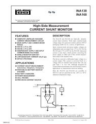
Launch Vehicle Zero (LV0)<br />
Launch Vehicle Zero (LV0) was the first rocket project developed by the <strong>PSAS</strong>.<br />
LV0's payload module was composed of 3 main systems: The Amateur Television<br />
Video (ATV) transmitter system, a vertically aligned (Z-axis) solid-state<br />
accelerometer that was fed into a 300 bps digital data down link, and an altimeter.<br />
The rocket-based ATV system was composed of a miniature NTSC black-and-white<br />
CCD camera and a transmitter tuned to the 70-cm band allocated for amateur<br />
television and radio. The signal from the CCD was fed into the transmitter, which<br />
broadcasted at 440 MHz to a ground station equipped with the appropriate antenna<br />
and receiver configuration. On the ground, the video signal was viewed real-time and<br />
recorded onto videotape.<br />
The Analog Device's ADXL50 solid-state (micro-machined) accelerometer was<br />
incorporated in a telemetry package designed to measure the rocket’s acceleration<br />
profile and transmit the data to the ground station. To accomplish this, the output<br />
from the accelerometer was digitized by a PIC16C73A microcontroller and directed<br />
to a 300 bps modem. The analog signal from the modem was transmitted to the<br />
ground via the audio channel of the ATV signal. On the ground the telemetry data was<br />
recorded onto a computer for later analysis.<br />
Also on board the rocket was a commercially available altimeter interfaced with a<br />
Motorola 68HC11 microcontroller and a 12-bit A/D converter. All data from the<br />
altimeter was stored in battery backed RAM, and retrieved for later analysis.<br />
Specifications for LV0 include:<br />
Airframe : Cardboard with 3 layers fiberglass<br />
Length : 72 inches<br />
Weight : 12.2 lbs.<br />
Motor : 700 Ns solid propellant motor<br />
Recovery : Payload - 4-ft parachute<br />
Body - 3-ft parachute<br />
Figure 1: Launch Vehicle Zero (LV0)<br />
AESS <strong>Avionics</strong> <strong>System</strong> <strong>Design</strong> <strong>Project</strong> – Rev. 3.1 – Page 9
LV0 contained no flight-sequencing computer. Separation and recovery were handled<br />
by a chemically timed motor ejection charge. The block diagram of the LV0 payload<br />
is shown below in Figure 2.<br />
ADXL50 Accelerometer<br />
300Hz BW, +/- 20g limits<br />
PIC16C73A Microcontroller<br />
Fosc = 1MHz<br />
Port A = 8bit A/D<br />
Port B = 8bit LED output<br />
Port C = 300bps UART<br />
Audio FSK Modulator<br />
Space (0) = 3KHz<br />
Mark (1) = 5kHz<br />
Audio In Video In<br />
Amateur TV Transmitter<br />
(426MHz, 1W)<br />
- Video in<br />
- Audio in<br />
Inverted V Dipole Antenna<br />
12V Power Supply<br />
2x 6V Li-Ion Batteries<br />
Power switch:<br />
On (batteries) / Off /<br />
On (External supply)<br />
Independent Logging<br />
Altimeter<br />
Commercially Available rocket<br />
altimeter. 9V, 68HC11, Sensym<br />
SCC15A pressure sensor<br />
B&W CCD Video Camera<br />
(NTSC output, Audio disabled)<br />
Figure 2: Launch Vehicle Zero (LV0) payload block diagram<br />
The launch of LV0 occurred on June 7th 1998 in Monroe, Washington. The rocket<br />
reached an altitude of 1200 feet, successfully transmitting live video to the ground<br />
and internally logging altimeter data throughout the flight. The separation and<br />
recovery system worked as predicted, but the digital downlink system failed due to a<br />
short in the data transmit line.<br />
The altimeter data from the LV0 flight is shown on the following page.<br />
AESS <strong>Avionics</strong> <strong>System</strong> <strong>Design</strong> <strong>Project</strong> – Rev. 3.1 – Page 10
Altitude<br />
1500<br />
1000<br />
500<br />
0<br />
LV0 Altimeter Readings<br />
1<br />
28<br />
55<br />
82<br />
109<br />
136<br />
163<br />
190<br />
217<br />
244<br />
271<br />
298<br />
325<br />
352<br />
379<br />
406<br />
433<br />
460<br />
Tenths of seconds<br />
Figure 3: Launch Vehicle Zero (LV0) altimeter data<br />
From the experience with LV0, the <strong>PSAS</strong> developed a number of improved design<br />
criteria for future launches. These include:<br />
• robust interconnects,<br />
• improved flight control via onboard flight computer, and<br />
• emergency flight control via radio uplink.<br />
Implementation of these criteria in a new rocket design led to the development of<br />
Launch Vehicle 1 (LV1).<br />
AESS <strong>Avionics</strong> <strong>System</strong> <strong>Design</strong> <strong>Project</strong> – Rev. 3.1 – Page 11
Launch Vehicle One (LV1)<br />
In addition to addressing the issues raised by LV0, the <strong>PSAS</strong> felt that it was necessary<br />
to begin developing basic avionics systems that could grow with future designs, and<br />
to include a scientific instrumentation payload for flight profiling and data logging.<br />
Specifications for LV1 include:<br />
Airframe : Carbon fiber body with fiberglass payload<br />
Length : 132 inches<br />
Weight : 46 lbs.<br />
Motor : Up to 10,000 Ns solid propellant motor<br />
Recovery : Payload - (3) 3.5 ft parachutes<br />
Body - 2 stage parachute (drogue/main)<br />
Figure 4: Launch Vehicle One (LV1)<br />
LV1 subsystems include a payload module and an Interface Plate Release <strong>System</strong><br />
(IPRS).<br />
The payload module includes the following components:<br />
• A color CCD video camera with an ATV transmitter,<br />
• a 2400bps digital data downlink for telemetry data,<br />
• a 2m amateur radio DTMF-activated uplink for manual recovery system<br />
control,<br />
• accelerometers and rotational gyro's measuring 3 linear axes and 3 rotational<br />
axes,<br />
• pressure and temperature sensors, and<br />
• a flight computer powered by a PIC17C42 microcontroller for flight<br />
sequencing.<br />
The accelerometers and rotational gyros form an Inertial Measurement Unit (IMU)<br />
with 6 degrees-of-freedom (6-DOF) which will serve as a prototype for the<br />
development of a future Inertial Navigation <strong>System</strong> (INS).<br />
AESS <strong>Avionics</strong> <strong>System</strong> <strong>Design</strong> <strong>Project</strong> – Rev. 3.1 – Page 12
X Axis ADXL150 Accelerometer<br />
Y Axis ADXL150 Accelerometer<br />
Z Axis ADXL150 Accelerometer<br />
α Axis EC-05V Gyroscope<br />
β Axis EC-05V Gyroscope<br />
γ Axis EC-05V Gyroscope<br />
MPX7100A Pressure Sensor<br />
LM54 Temperature Sensor<br />
Backup Separation <strong>System</strong><br />
3bit command<br />
MAX197 12bit ADC<br />
(8ch Mux, 8+4 out)<br />
Flight Computer<br />
(PIC17C756 Microcontroller)<br />
Fosc = 33MHz<br />
Bipolar Transistor<br />
Firing Circuit<br />
Separation Charge Igniter<br />
Figure 5: Launch Vehicle Zero (LV1) payload block diagram<br />
AESS <strong>Avionics</strong> <strong>System</strong> <strong>Design</strong> <strong>Project</strong> – Rev. 3.1 – Page 13<br />
Amateur TV Transmitter<br />
TDK73M223 Modem Chip<br />
(2400bps)<br />
9V Battery<br />
The Interface Plate Release <strong>System</strong> (IPRS) is responsible for deploying the main<br />
rocket body's recovery chutes and is independent of the main payload module. As<br />
shown in the flight profile (shown on the next page in Figure 6), the main rocket body<br />
falls toward the earth until the pressure sensors or internal timers indicate that it is<br />
time to deploy the chutes. Earlier release of the chutes would result in excessive<br />
'hang-time', complicating location and retrieval of the rocket body; later release of the<br />
chutes (known as a 'lawn-dart' landing) would simplify location and retrieval of the<br />
rocket body but could result in unacceptable damages.<br />
Additional LV1 details are shown in Figure 6, on the next page:
Figure 6: Additional specification details for LV1<br />
AESS <strong>Avionics</strong> <strong>System</strong> <strong>Design</strong> <strong>Project</strong> – Rev. 3.1 – Page 14
The planned flight profile for LV1 is shown below.<br />
Separation<br />
Based on accelerometer<br />
data, PIC should cause<br />
nosecone separation<br />
DTMF manual separation if<br />
PIC fails. Determined by<br />
time and video image.<br />
Ascent<br />
Motor burns out<br />
at 6.07 seconds<br />
Boost<br />
Launch<br />
Apogee<br />
Max acceleration<br />
at 4.26 seconds<br />
Payload<br />
deployment<br />
PIC #2 releases interface<br />
plate. Determined by<br />
pressure data.<br />
Backup: PIC #2<br />
releases interface plate.<br />
Determined by internal<br />
timers.<br />
Figure 7: Flight profile for LV1<br />
Descent<br />
AESS <strong>Avionics</strong> <strong>System</strong> <strong>Design</strong> <strong>Project</strong> – Rev. 3.1 – Page 15
The launch of LV1 occurred on April 11th 1999 at the <strong>PSAS</strong> launch site near<br />
Millikan, Oregon. The rocket reached an altitude of slightly more than 12000 ft,<br />
successfully transmitting data and video to the ground support station throughout the<br />
flight.<br />
A total of 11,252 Z-axis acceleration data points were received from the rocket<br />
throughout the flight, sampled by the MAX197 12-bit A/D converter. Of these, there<br />
were approximately 230 obviously erroneous values resulting from bit-flips; 60% of<br />
these errors were bit-sets (a false ‘1’ detected) and 40% were bit-clears (a false ‘0’<br />
detected). The errors were corrected by determining whether or not an outlying data<br />
point differed from the general trend by the addition or subtraction of a large power of<br />
2 corresponding to one of the 4 most significant bits (MSBs). Obviously it is likely<br />
that there were bit-flips in the lower bits as well, but these would be more difficult to<br />
detect since the deviation from the general trend would be less noticeable.<br />
If we assume that bit-flip errors can be reliably detected only if they occur in the 4<br />
most significant bits, then only one third of the errors were detected and the total<br />
reception error is (3 times the detected error) = 3 * 230 errors / 11252 total points =<br />
6% error. Future systems must include cyclical redundancy check (CRC), error<br />
correction code (ECC), or some other mechanism which is capable of detecting and<br />
possible correcting this sort of error.<br />
Figure 8 (next page) shows the Z-axis acceleration profile for the flight of LV1. The<br />
numbered labels denote interesting portions of the flight; these are discussed below.<br />
A note on terminology: all acceleration descriptions are referenced to the ground, i.e.<br />
‘negative acceleration’ is the result of forces that push the body upwards or create a<br />
downward pull on the sensor (such as the rocket motor, the separation charge, and the<br />
earth’s gravitational field), and ‘positive acceleration’ is the result of forces that push<br />
the body downward (such as wind resistance effects and the opening of the chutes<br />
while the rocket was still ascending).<br />
1. Boost phase<br />
Prior to liftoff, the only acceleration experienced by the rocket was a steady 1<br />
‘g’ downward. At time t = 0s, the motor ignited and the rocket left the<br />
launchpad. Maximum acceleration was reached at time t = 2.17s, when the<br />
rocket was experiencing 7.27 ‘g’s downward.<br />
2. Ascent phase<br />
As the motor continued to burn through its thrust curve, the diminishing<br />
effects of the motor thrust and the increasing effects of air resistance (which is<br />
proportional to the cube of the velocity) reduced the acceleration. At t = 6.3s,<br />
the air resistance component of the acceleration began to exceed the thrust<br />
component and the net acceleration on the avionics system became positive.<br />
AESS <strong>Avionics</strong> <strong>System</strong> <strong>Design</strong> <strong>Project</strong> – Rev. 3.1 – Page 16
Shortly thereafter (at time t = 6.54s) the peak velocity of 596.2mph (0.795<br />
Mach) was reached. As the rocket continued upwards, the effects of the air<br />
drag continued to negate the acceleration from the motor, as shown by the<br />
asymptotic decay of the graph towards zero.<br />
3. Separation<br />
At time t = 26.75s, the payload/avionics system was forcibly separated from<br />
the rocket body by the separation charge, giving the payload a slight boost in<br />
upward velocity.<br />
4. Chute Deployment<br />
As the chutes deploy from the rear of the module, the payload experiences a<br />
sudden deceleration.<br />
5. Descent<br />
The avionics system floats to the ground. Acceleration oscillates around 1 ‘g’<br />
downward due to the swinging of the avionics system on the three payload<br />
chutes. Note that the graph shows only the first 39 seconds of flight- the<br />
actual time of flight was 466 seconds.<br />
Figure 8: LV1 Z-axis acceleration data<br />
AESS <strong>Avionics</strong> <strong>System</strong> <strong>Design</strong> <strong>Project</strong> – Rev. 3.1 – Page 17
Figure 9 (shown on the next page) shows the Z-axis velocity profile for the flight of<br />
LV1. This data was obtained by integrating the acceleration data (disregarding the<br />
constant 1’g’ acceleration due to gravity). Despite the accumulative errors that result<br />
from the integration process, this profile shows the expected behavior:<br />
1. Boost phase<br />
Velocity was initially zero as the rocket sat on the launch pad. At time t = 0s,<br />
the motor ignited and the rocket accelerated upwards, rising steadily<br />
throughout the boost phase.<br />
2. Ascent phase<br />
At 6.54s, the motor burn is complete and the air resistance exerts its effect on<br />
the speed of the rocket throughout the coast phase. The rocket is still<br />
continuing upwards as air resistance and gravity erode its momentum.<br />
3. Separation<br />
At 26.75s, the separation charge ignites, giving a slight boost to the velocity of<br />
the payload as it is ejected from the main body. Though the rocket still has a<br />
non-zero upward velocity, the separation effectively declared this point to be<br />
apogee, since the rocket will not continue upwards when the nosecone is<br />
absent and the chutes deploy. (The rocket was not in fact going 25 mph at<br />
separation as the graph shows. This discrepancy is due to accumulative<br />
integration errors).<br />
4. Chute Deployment<br />
As the chutes deploy from the rear of the module, payload velocity decreases<br />
to zero and then becomes negative as the payload begins to descend. There is<br />
a sudden impulse as the nosecone, which houses the telemetry package, is<br />
stopped by the chutes and reverses direction.<br />
5. Descent<br />
The chutes quickly restrict the payload to its terminal velocity.<br />
AESS <strong>Avionics</strong> <strong>System</strong> <strong>Design</strong> <strong>Project</strong> – Rev. 3.1 – Page 18
Velocity [mph]<br />
650.0<br />
550.0<br />
450.0<br />
350.0<br />
250.0<br />
150.0<br />
50.0<br />
-50.0<br />
LV1 Velocity vs Time<br />
-2 3 8 13 18<br />
Time [seconds]<br />
23 28 33 38<br />
Figure 9: Velocity profile for LV1<br />
Integrating the acceleration data a second time produces a graph of the position. The<br />
accumulated integration errors, however, severely undermine the validity of the graph,<br />
as shown in Figure 10 below.<br />
Figure 10:Position profile for LV1<br />
AESS <strong>Avionics</strong> <strong>System</strong> <strong>Design</strong> <strong>Project</strong> – Rev. 3.1 – Page 19
Height (in Feet)<br />
To more accurately determine the height of the rocket, the pressure sensor data was<br />
analyzed as shown in Figure 11 below. This data lent itself to a much more<br />
meaningful interpretation.<br />
12000<br />
11000<br />
10000<br />
9000<br />
8000<br />
7000<br />
6000<br />
5000<br />
4000<br />
3000<br />
2000<br />
1000<br />
0<br />
LV1 Altitude vs Time from MPX5100A Pressure Sensor Data<br />
-10 40 90 140 190 240 290 340 390 440<br />
Time (in seconds)<br />
Figure 11:Pressure sensor altitude profile for LV1<br />
As shown in the previous graphs, it may be necessary to combine a number of sources<br />
of data to determine the ‘correct’ telemetry. For an actively guided system, it will be<br />
necessary to combine data from the accelerometers and pressure sensors as well as<br />
possible Global Positioning <strong>System</strong> (GPS) data and radio packet time-of-flight<br />
indicators. Other possibilities include a sun sensor mounted in the nosecone and<br />
high-performance sensors such as ring laser gyros.<br />
With all telemetry measurements it will be necessary to account for signal latency.<br />
Time-of-flight, GPS satellite linkup, and even A/D-conversion delays become<br />
significant when the rocket is moving at speeds nearing 1 Mach, since by the time a<br />
reading has been processed a large distance will have been covered by the rocket.<br />
This will necessitate a successive-approximation approach wherein the avionics<br />
package will use its current position and heading data to predict where it will be when<br />
the next reading occurs; the next reading can then be used to update the<br />
approximation and minimize positional error.<br />
AESS <strong>Avionics</strong> <strong>System</strong> <strong>Design</strong> <strong>Project</strong> – Rev. 3.1 – Page 20
Launch Vehicle Two (LV2)<br />
To achieve orbit (or very high altitudes) it is necessary to integrate an Inertial<br />
Measurement Unit (IMU) with an active guidance system to create an Inertial<br />
Navigation <strong>System</strong> (INS). Prior <strong>PSAS</strong> rockets have taken steps to develop an IMU as<br />
a proof-of-concept for the INS.<br />
The development of such an INS will require modular independent subsystems which<br />
can be individually upgraded and evolved without compromising the stability,<br />
precision, and safety of the overall system. It is toward this end that we designed the<br />
following architecture for Launch Vehicle Two (LV2).<br />
Having observed both the present lack of advanced systems and the future need for<br />
those systems, it became apparent that an intermediate step was required. The<br />
development of a system with modular components would allow for the systematic<br />
qualification of subsystems needed for future launch capabilities. Extending the<br />
modularity idea to the airframe as well as the avionics will ensure that the entire<br />
system is scalable.<br />
Of particular importance is the validation and testing of the IMU subsystem. The<br />
IMU sensor suite and the data streaming algorithms used to transmit and store that<br />
data need to be qualified for use with an INS system. Data from this system will be<br />
used to generate flight profiles for flight sequencing tests and flight path calculation in<br />
future rocket projects.<br />
The initial development of LV2 embodies a clarification of the direction and goals of<br />
the <strong>PSAS</strong>. Rather than being an interim design on the path to an advanced system,<br />
LV2 will serve as a continuously upgradable modular design that allows the testing<br />
and validation of a wide range of avionics, payload, and airframe ideas.<br />
The airframe design for LV2 will result in a modular launch vehicle which can be<br />
assembled into any configuration required for a flight. Fins, motor modules, and<br />
payload sections can be added, swapped, or removed, allowing for the testing and<br />
validation of various flight configurations. This modular approach will provide the<br />
<strong>PSAS</strong> with an evolvable launch vehicle which will serve as a testbed for avionics and<br />
propulsion design for years to come.<br />
It should also be noted that for LV2 the concept of ‘payload’ has been redefined to a<br />
more traditional interpretation: a payload is an independent package carried by the<br />
rocket. The term was previously used to describe the flight control systems of the<br />
rocket, which will henceforth be known as ‘avionics’. Payload development is<br />
outside of the scope of this document.<br />
AESS <strong>Avionics</strong> <strong>System</strong> <strong>Design</strong> <strong>Project</strong> – Rev. 3.1 – Page 21
Development of the avionics package began with a functional decomposition of the<br />
overall system, which resulted in a number of functionally discrete system task blocks<br />
that must be accomplished in a successful flight. In keeping with our goal that the<br />
system be as modular as possible, the avionics team chose to embody each of these<br />
blocks as a separate subsystem. This will ensure that replacement of a subsystem will<br />
not affect other subsystems that are functionally distant. If each module has a clearly<br />
defined interface, individual subsystems can be swapped for upgrade or repair without<br />
affecting the overall functionality of the avionics system.<br />
Based on the results of LV0 and LV1, the <strong>PSAS</strong> met to discuss the requirements for<br />
the next launch vehicle and to clarify the focus and goals for the future. This<br />
discussion led to the development of a list of requirements that the avionics package<br />
must embody subject to a list of constraints. These requirements and constraints were<br />
given to the avionics team to guide the design of the new avionics package. In the<br />
next section of this document, we will define the problem at hand and discuss the<br />
motivating factors that influence the design.<br />
Figure 12: Possible Configuration of LV2<br />
AESS <strong>Avionics</strong> <strong>System</strong> <strong>Design</strong> <strong>Project</strong> – Rev. 3.1 – Page 22
Problem <strong>State</strong>ment<br />
To design, implement, and validate an avionics module consisting of a flight sequence<br />
computer, an inertial measurement unit, a solid-state data recorder, a data acquisition<br />
package, and a communications system for the PSU Aeronautics Society’s amateur<br />
launch vehicle LV2. This avionics module will serve as a scalable development and<br />
qualification testbed which can be expanded to accommodate a future active guidance<br />
system.<br />
AESS <strong>Avionics</strong> <strong>System</strong> <strong>Design</strong> <strong>Project</strong> – Rev. 3.1 – Page 23
Constraints<br />
The payload system design is subject to the following constraints:<br />
• All systems must use the 'PIC' microcontroller architecture from<br />
Microchip Technology Inc. to match existing AESS systems.<br />
• The system must minimize weight.<br />
• The system must minimize power consumption and operate on 12VDC<br />
to match existing AESS systems.<br />
• The system is subject to space requirements imposed by the design of<br />
the existing LV2 avionics bay.<br />
• For forward design mobility, modular boards with robust quick<br />
disconnects should be used.<br />
• The system must be able to withstand 20g’s acceleration.<br />
• Critical systems should include redundant backups: 2 software<br />
backups, and one physical backup; reliability is very important.<br />
• The system should be inexpensive, using off-the-shelf components and<br />
(where possible) industry samples.<br />
• The system should be reproducible, using common parts and<br />
construction techniques.<br />
• Modularity is of the utmost importance. There must be a consistent<br />
logical and physical interface to the system.<br />
AESS <strong>Avionics</strong> <strong>System</strong> <strong>Design</strong> <strong>Project</strong> – Rev. 3.1 – Page 24
<strong>Design</strong> Requirements<br />
The following requirements were developed by the avionics design team in<br />
conjunction with <strong>PSAS</strong> team members. The payload system must contain the<br />
following elements and meet the goals listed below:<br />
Overall<br />
The entire system must be modular and evolvable to meet the functional<br />
requirements for many future launches.<br />
Sensors:<br />
Sensor are functionally divided into two categories, proprioceptive and external.<br />
Proprioceptive (‘self-perceiving’) sensors monitor the status of the rocket, while<br />
external sensors monitor environmental conditions.<br />
Proprioceptive sensors<br />
Dedicated sensors must include:<br />
• Igniter validation sensors to determine if the igniters are open, shorted,<br />
or valid. This information is relayed to the flight computer and the<br />
Downlink for pre-launch systems validation.<br />
• Launch detect monitor to determine the moment of separation from the<br />
launchpad. This information is relayed to data storage as well as the<br />
Downlink for accurate ground support flight sequencing and flightpath<br />
determination.<br />
• Separation monitor to determine the moment of separation of the<br />
Payload module from the main body during recovery.<br />
• Power status sensors to monitor the on-board power supply.<br />
Subsystem status sensors must include:<br />
• Flight state monitors which will gather data from the on-board<br />
subsystems and the radio Uplink.<br />
• Subsystem status checks to update the states in the flight computer.<br />
External sensors<br />
External sensors must include:<br />
• Inertial measurement sensors: accelerometers to determine linear<br />
motion in 3 axes and gyros to determine rotational motion in 3 axes.<br />
Data acquisition sensors must include:<br />
• Temperature and pressure sensors<br />
• Strain gauges to determine the physical dynamics of the rocket in flight<br />
Imaging sensors must include:<br />
• Video, to be broadcast to ground support.<br />
AESS <strong>Avionics</strong> <strong>System</strong> <strong>Design</strong> <strong>Project</strong> – Rev. 3.1 – Page 25
Communications:<br />
Uplink<br />
Manual recovery system which must include the ability to interface with<br />
the flight computer for manual status checks, arming of the system, and<br />
emergency control of the payload separation system.<br />
Downlink<br />
Telemetry data and video must be sent back to ground support.<br />
Communications subsystem<br />
This subsystem will handle the routing of all air-to-ground and intersubsystem<br />
communications.<br />
Data storage:<br />
• ‘Black box’ for raw data storage<br />
• Raw data from the telemetry sensors and the flight computer will be stored<br />
for later recovery and analysis.<br />
• Telemetry sent to base station on ground<br />
• Telemetry data and flight computer status must be sent to the ground<br />
support for monitoring and storage.<br />
Flight Computer:<br />
The flight computer must control flight sequencing based on internal state<br />
machines, input from other subsystems, and uplink data.<br />
AESS <strong>Avionics</strong> <strong>System</strong> <strong>Design</strong> <strong>Project</strong> – Rev. 3.1 – Page 26
Architectural considerations<br />
To reach the goals outlined above, we examined a number of different possible<br />
architectures. A summary of the possibilities is shown below.<br />
Central/Monolithic Architecture<br />
The current (LV1) rocket uses a monolithic payload system in which all tasks are<br />
performed by one main computer. The limitations inherent in this architecture, a<br />
block-diagram of which is shown in Figure 13 below, were the primary source of<br />
motivation for the design of a new system.<br />
Sensors Igniters<br />
IMU<br />
Uplink<br />
Flight Computer<br />
Downlink<br />
Flight Recorder<br />
Figure 13:Monolithic architecture block diagram<br />
Pros:<br />
• Simple: easy to implement.<br />
• Consolidated: all resources are part of the primary computer, so no<br />
complex communications protocols need to be developed.<br />
• Lightweight: minimal component count keeps weight down.<br />
• Small: this system minimizes the amount of space taken up within the<br />
payload structure.<br />
Cons:<br />
• Non-scaleable: future additions to the payload would place unrealistic<br />
demands on system resources due to limited pin count.<br />
• Too localized: a failure in non-critical subsystems could lock up the<br />
primary flight computer.<br />
• Overloaded: with all tasks being performed by one central computer,<br />
the processor that is in charge of flight sequencing must spend most of<br />
its clock cycles shuffling data.<br />
• Requires a specific Flight Computer architecture to meet the hardware<br />
port requirements.<br />
This architecture, while adequate for the first <strong>PSAS</strong> systems, is rapidly<br />
approaching saturation as existing subsystems are upgraded and additional<br />
subsystems are added. To adequately meet the needs of future systems, a different<br />
architecture is required.<br />
AESS <strong>Avionics</strong> <strong>System</strong> <strong>Design</strong> <strong>Project</strong> – Rev. 3.1 – Page 27
Serial Architecture (direct)<br />
Since all candidate microcontrollers have an onboard serial port, one option for<br />
the system architecture was a serial bus. We considered two types of serial<br />
configurations: a ring architecture, shown in Figure 14, and an arbitrated<br />
architecture, shown in the next section.<br />
Uplink IMU Sensors Flight Computer Igniters<br />
Flight Recorder<br />
Downlink<br />
Figure 14:Serial ring architecture block diagram<br />
The ring serial architecture provides all subsystems with a communications path<br />
to all other subsystems, but it requires each subsystem to pass along a substantial<br />
amount of data that is intended for a different target.<br />
Pros:<br />
• Simple: very basic structure.<br />
• Ease of implementation: uses only on-chip serial communications<br />
hardware (SPI, USRT, and UART protocols).<br />
• Expandable: this architecture can be ‘daisy-chained’ indefinitely as<br />
new subsystems are added.<br />
Cons:<br />
• Bandwidth: each subsystem must be capable of passing large amounts<br />
of data, most of which is not needed by any one system, or<br />
• Ownership: each subsystem must have knowledge of what data is<br />
needed further down the chain.<br />
• Fragile: this architecture is not fault-tolerant. If one subsystem goes<br />
offline, they all do.<br />
AESS <strong>Avionics</strong> <strong>System</strong> <strong>Design</strong> <strong>Project</strong> – Rev. 3.1 – Page 28
Serial Architecture (arbitrated)<br />
The arbitrated serial architecture uses a separate subsystem (the ‘arbiter’) to grant<br />
access to a single bi-directional serial bus as each subsystem needs it. When a<br />
subsystem desires access to the bus, it asserts its REQ (request) line to announce<br />
that it is requesting the bus. When the bus is free, the arbiter (using some fairness<br />
algorithm to allocate the bus where it is needed without locking out the low<br />
bandwidth subsystems) asserts the GNT (grant) line of the subsystem, allowing<br />
the subsystem to take control of the bus. Various timeout protocols and<br />
restrictions on the length of time any one subsystem can control the bus would be<br />
implemented in an attempt to ensure that all subsystems are able to transport their<br />
data. Figure 15 shows a detail of the system connections.<br />
REQ<br />
GNT<br />
To bus<br />
REQ<br />
GNT<br />
To bus<br />
IMU Uplink<br />
Flight Recorder GNT<br />
AESS <strong>Avionics</strong> <strong>System</strong> <strong>Design</strong> <strong>Project</strong> – Rev. 3.1 – Page 29<br />
REQ<br />
To bus<br />
Arbiter<br />
REQ1 GNT1<br />
Shared Serial Bus<br />
Figure 15:Detail of arbitrated serial bus<br />
Pros:<br />
• Orderly: no device contention due to the arbiter<br />
• Scaleable: can be expanded indefinitely as new subsystems are added.<br />
• Fault-tolerant: if one system goes offline, the other systems are not<br />
materially affected (though the lack of information from the offline<br />
system might affect other subsystems).<br />
Cons:<br />
• Implementation: requires arbitration hardware in addition to built-in<br />
serial communications hardware. As the number and complexity of<br />
payload subsystems grows, the arbiter would require additional<br />
resources and the bus would become increasingly overloaded.<br />
• Bandwidth: one serial bus is responsible for all of the system’s data<br />
flow, thereby creating a bottleneck when more than one system needs<br />
to move large amounts of data.<br />
For either of these two implementations of the serial architecture, the ‘cons’ far<br />
outweigh the ‘pros’. Since all of the negative aspects of this system are in direct<br />
conflict with project constraints and requirements, we discarded this architecture<br />
as a possible candidate.<br />
GNT2<br />
REQ2<br />
GNT3<br />
REQ3
Distributed Architecture<br />
To reduce the amount of communications bandwidth required by any one<br />
subsystem, we next considered a distributed architecture, as shown in Figure 16.<br />
This architecture provides maximal interconnection between subsystems, thereby<br />
reducing the load on any single bus.<br />
IMU<br />
Uplink<br />
Sensors<br />
Flight Computer<br />
Igniters<br />
Flight Recorder<br />
Figure 16:Distributed architecture block diagram<br />
AESS <strong>Avionics</strong> <strong>System</strong> <strong>Design</strong> <strong>Project</strong> – Rev. 3.1 – Page 30<br />
Downlink<br />
Pros:<br />
• Bandwidth: each bus has significantly reduced bandwidth;<br />
subsystems are only presented with the data they need.<br />
• Fault-tolerant: a failure in any one subsystem will only affect systems<br />
that rely on the data from that subsystem.<br />
Cons:<br />
• Increased hardware and software complexity: each subsystem has an<br />
increased need for communications ports to accommodate the<br />
distributed structure of the system.<br />
• Requires a specific Flight Computer architecture to meet the hardware<br />
port requirements.<br />
The increase in complexity that this architecture provides is fundamentally<br />
opposed to the desire to make the system modular and scaleable. If any one<br />
system needs to be replaced, numerous communications protocols must be<br />
followed to ensure proper connections to the other systems. This places<br />
additional requirements on the communications hardware that must be supported<br />
by each chip. Based on this limitation, we chose not to consider this distributed<br />
model as a candidate architecture.
Modular Architecture<br />
In attempt to find some optimal middle ground, we took desired features from the<br />
previously-discussed architectures and combined them into a modular<br />
architecture, as shown in Figure 17.<br />
Sensors<br />
Sensors<br />
Igniters<br />
IMU<br />
Data Acquisition<br />
Flight Computer<br />
Communications<br />
Uplink<br />
Flight Recorder<br />
Downlink<br />
Figure 17:Modular architecture block diagram<br />
Pros:<br />
• Minimizes the complexity of the communications systems within<br />
modules that are not primarily communications oriented.<br />
• Modules can be upgraded or interchanged with other modules that<br />
have the same interconnect specifications.<br />
Cons:<br />
• Communications computer must be able to handle significant<br />
bandwidth through a large number of connections.<br />
• Hardware port requirements dictate Flight Computer architecture.<br />
In keeping with the idea that individual modules should be isolated according to<br />
function, we considered the addition of a subsystem whose sole job would be to<br />
route communications between the other modules. This Communications<br />
Computer would be the only chip in the system with complex communications<br />
needs; all other subsystems could focus on their tasks without the additional<br />
burden of routing data packets.<br />
The primary drawback of this architecture is that all system functionality is<br />
dependent on the proper operation of the CC. While it is still possible to revert to<br />
backup mechanisms (such as internal timers) to accomplish the flight sequencing,<br />
subsystems that are operational will be effectively disabled by a CC failure. We<br />
therefore chose to consider other architectures for our implementation.<br />
AESS <strong>Avionics</strong> <strong>System</strong> <strong>Design</strong> <strong>Project</strong> – Rev. 3.1 – Page 31
Serial Architecture with Hardware Arbitration<br />
Recent advances in serial bus design have resulted in the creation of hardwarearbitrated<br />
buses that provide a modular and robust method for component<br />
interconnection. One specification for this type of network is the Controller Area<br />
Network (CAN or CANbus). Originally developed for the automotive industry,<br />
the CANbus serial protocol was designed to provide reliable real-time data<br />
connections in non-ideal industrial environments.<br />
CAN provides many features which will be useful in the context of avionics<br />
systems. Hardware arbitration, automatic retransmission of messages when an<br />
error occurs, and message prioritization will simplify the task of developing a<br />
robust fault-tolerant network.<br />
Termination Termination<br />
Figure 18:CANbus architecture block diagram<br />
Pros:<br />
• Emphasizes modularity. Any subsystem can be added to the overall<br />
design by adding bus interface hardware to the subsystem.<br />
• Emphasizes reliability. Many fault recovery and prevention features<br />
are built into the hardware specification.<br />
• Consistent hardware interface for all modules.<br />
• Provides a convenient mechanism for prioritizing data packets.<br />
Cons:<br />
• Limited bandwidth. Maximum bus speed is 1Mbps.<br />
The CANbus architecture allows for the creation of a scalable, modular network<br />
which provides significant hardware-based mechanisms for ensuring the reliable<br />
transmission of data. As with the arbitrated serial bus discussed previously, there<br />
is a reduction in available bandwidth when using this architecture; nevertheless<br />
the benefits afforded by this implementation greatly outweigh the drawbacks.<br />
AESS <strong>Avionics</strong> <strong>System</strong> <strong>Design</strong> <strong>Project</strong> – Rev. 3.1 – Page 32
Implementation<br />
In the final analysis, we chose to use the hardware-arbitrated serial CANbus architecture<br />
(discussed in the previous section) as the foundation for our avionics system design. This<br />
architecture efficiently embodies the motivating characteristics required for the target<br />
system, providing us with a very scalable and modular implementation that will support<br />
hardware revisions and upgrades throughout the development cycle of the next few<br />
upcoming launch vehicles.<br />
Use of the CANbus allows us to embody each of the functionally separate task blocks<br />
(listed in the <strong>Design</strong> Requirements) as physically distinct devices capable of<br />
communicating with all other devices on the network. This dramatically simplifies the<br />
task of upgrading and replacing avionics components, since each subsystem can be<br />
replaced with any device that follows that subsystem’s communications protocol. The<br />
functional isolation also lends itself to a modular development style in which each<br />
subsystem can be independently qualified and tested before it is interfaced to the rest of<br />
the network.<br />
In this section we will provide an introduction to the CANbus, starting with an overview<br />
of the CAN specification, some discussion on arbitration and prioritization techniques,<br />
and a description of the method in which CAN was implemented in our design. We will<br />
then discuss each of the subsystems in the avionics package, describing their hardware,<br />
software, and messaging details.<br />
Finally, in the ‘Operations’ section we will discuss how the individual subsystems are<br />
united to form a coherent unified avionics package, and the ‘Ground Support’ section will<br />
describe some of our ideas for linking our airborne design to the computers on the<br />
ground.<br />
AESS <strong>Avionics</strong> <strong>System</strong> <strong>Design</strong> <strong>Project</strong> – Rev. 3.1 – Page 33
CANbus Overview<br />
CAN (Controller Area Network) is an ISO approved standard for a low-cost, fault<br />
tolerant, and robust real-time communication protocol. Initially developed by<br />
Robert Bosch for in-vehicle data transfer in 1984, silicon became available in<br />
1987 and CAN was first used in cars in 1992. The draft international standard<br />
was introduced in 1991 and this became a full standard (ISO 11898) in 1994.<br />
The serial bus structure gives two advantages over parallel bus systems: increased<br />
transfer reliability even over large distances and more favorable costs. The CAN<br />
specifications define a multi-master priority based bus access which uses carrier<br />
sense multiple access with collision detection and non-destructive arbitration.<br />
(CSMA/CD + NDA). This hardware-based arbitration scheme provides system<br />
wide data consistency.<br />
CAN allows multicast reception with time synchronization error detection and<br />
error signaling. Corrupted messages are automatically retransmitted and defective<br />
nodes are automatically removed from the circuit. Nodes can make remote data<br />
requests. The signaling uses non-return to zero (NRZ) bit encoding and allows<br />
full isolation of the interconnecting wires.<br />
The CAN implementation of the arbitrated serial bus architecture is being used in<br />
other aeronautics projects as well: the Alpha Magnetic Spectrometer (AMS),<br />
tested aboard the space shuttle Discovery in June of 1998 and ultimately destined<br />
for the international space station, uses the CAN architecture for internal<br />
communications between subsystems.<br />
How does CAN work?<br />
Information transmitted on the CANbus is organized into small packets called<br />
"Frames". A frame consists of some data-addressing information (a message<br />
Identifier which also determines the priority of the message), up to eight bytes of<br />
data, and some error checking. When a frame is transmitted, each receiving node<br />
will acknowledge that the frame has been correctly received by inserting an<br />
acknowledge bit into a space left in the frame by the transmitting node, which can<br />
then determine that at least one node has correctly received the frame.<br />
The CANbus protocol is data-addressed rather than node-addressed. The content<br />
of the message (e.g. Acceleration data, Igniter checks, Subsystem status, etc.) is<br />
labeled by an identifier that is unique throughout the network. All other nodes on<br />
the network receive the message and each performs an acceptance test on the<br />
identifier to determine if the message, and thus its content, is relevant to that<br />
particular node. The "Identifier" part of the CANbus frame is used to both<br />
identify a message and indicate the message’s priority.<br />
AESS <strong>Avionics</strong> <strong>System</strong> <strong>Design</strong> <strong>Project</strong> – Rev. 3.1 – Page 34
Bus arbitration is handled through CSMA/CD with NDA (Carrier Sense Multiple<br />
Access / Collision Detect with Non-Destructive Arbitration). When a node is<br />
ready to transmit a message across the network, it must first verify that the bus is<br />
in the idle state (Carrier Sense). If the bus is idle, the node becomes the bus<br />
master and transmits its message. All other nodes detect the beginning of a<br />
message frame, switch to receive mode, and send an acknowledge after correct<br />
reception of the message.<br />
If more than one node starts to transmit at the same time (Multiple Access),<br />
message collision is avoided by a bit-wise arbitration scheme. As each<br />
transmitting node sends the bits of its message identifier, it monitors the bus level.<br />
A node that sends a recessive bit but detects a dominant one loses bus arbitration<br />
and switches into receive mode (Collision Detect/Non-Destructive Arbitration).<br />
This results in a prioritization scheme in which higher priority messages are given<br />
an Identifier with higher order dominant bits. Nodes whose messages are<br />
subsumed by higher-priority messages will attempt to resend the message when<br />
the bus becomes idle.<br />
Figure 19 demonstrates the arbitration process by which a node determines that it<br />
has lost bus-master status. The top signal shows the output from the node in<br />
question, while the bottom signal shows the actual signal level present on the bus.<br />
(Signal sense is electrically active-low, not logical; a ‘low’ level represents a<br />
dominant bit). When the ninth identifier bit (ID.2) is transmitted, the transmitting<br />
node observes that the signal level on the bus is dominant, while the output from<br />
the node is recessive. Logically, this represents a case where the node in question<br />
wishes to transmit a message with priority ‘11000100000’ (logical) while a<br />
remote node on the bus wishes to send a message with priority ‘11000100100’.<br />
The transmitting node therefore loses arbitration since the remote node wishes to<br />
transmit a message with a higher priority. When the transmitting node detects that<br />
it has lost bus-master status (when it receives ID.2, in this case), it switches to<br />
receive mode.<br />
Tx<br />
Rx<br />
Start of frame Arbitration lost<br />
ID.10 ID.9 ID.8 ID.7 ID.6 ID.5 ID.4 ID.3 ID.2 ID.1 ID.0<br />
Figure 19:Example of arbitration/prioritization scheme<br />
AESS <strong>Avionics</strong> <strong>System</strong> <strong>Design</strong> <strong>Project</strong> – Rev. 3.1 – Page 35
Identifiers<br />
As mentioned above, the unique identifier also determines the priority of the<br />
message. The lower the (electrical) numerical value of the identifier, the higher<br />
the priority of the message.<br />
The higher priority message is guaranteed to gain bus access as if it were the only<br />
message being transmitted. Lower priority messages are automatically retransmitted<br />
in the next bus cycle, or in a subsequent bus cycle if there are still<br />
other, higher priority messages waiting to be sent.<br />
Addressing and Arbitration<br />
While an arbitrary 11-bit message identifier allows for up to 2 11 = 2048 unique<br />
messages, the CANbus implementation allows for only 2032. The 16 messages<br />
that correspond to the case where the 7 MSB of the message identifier are<br />
recessive are not allowed due to the fact that the Dataframe ‘end-of-frame’<br />
delimiter consists of 7 consecutive recessive bits.<br />
There are 2 bus electrical states: dominant, which represents ‘0’ or ‘actively<br />
driven’, and recessive, which represent ‘1’ or ‘inactive’. The bus must be a<br />
"wired-or": in other words, if any node transmits a dominant bit, then the bus will<br />
be in the dominant state. All nodes must transmit a recessive bit for the bus to be<br />
recessive.<br />
Each node monitors the bus, and does not start a transmission if a frame is being<br />
transmitted by another node. If two nodes commence transmission at exactly the<br />
same time, the identifiers (which are transmitted first) will overlap. As the<br />
protocol prohibits two nodes transmitting the same identifier, the output state of<br />
the two should differ at some time during the identifier. In this case, the node<br />
transmitting the recessive bit will see a dominant bit on the bus and cease<br />
transmission. Since the MSB of the identifier is transmitted first, the lowest binary<br />
value of identifier always "wins", hence has the higher priority.<br />
Error-Checking<br />
CANbus uses self-checking, bit stuffing, an "in-frame" acknowledge and a CRC<br />
to check that messages are correctly transmitted and received. An incorrect<br />
message will be flagged by all nodes on the bus, and a re-transmission will be<br />
automatically triggered. The probability of a received message being erroneous is<br />
very low.<br />
The CAN protocol has five methods of error checking, three at the message level<br />
and two at the bit level. If a message fails any one of these error detection<br />
methods it will not be accepted and an error frame will be generated which will<br />
AESS <strong>Avionics</strong> <strong>System</strong> <strong>Design</strong> <strong>Project</strong> – Rev. 3.1 – Page 36
cause all other nodes to ignore the defective message and the transmitting node to<br />
resend the message.<br />
At the message level, a cyclical-redundancy check (CRC), an Acknowledge field<br />
within the message, and a form check are used to detect errors. The 15-bit CRC is<br />
carried out over the Identifier field and the Data bytes, and then compared to the<br />
CRC filed within the message. If the values differ, an error is generated. The<br />
Acknowledge field is two bits long and consists of an acknowledge bit and an<br />
acknowledge delimiter bit. The transmitter will place a recessive bit in the<br />
acknowledge field. Any node that receives the message correctly will write a<br />
dominant bit in the acknowledge field. If the transmitter does not detect a<br />
dominant bit in the acknowledge field, it will generate an error frame and<br />
retransmit the message. The third message-level error check is a form check<br />
which verifies that certain fields in the message contain only recessive bits. If a<br />
dominant bit is detected, an error is generated. The bits checked are the start-offrame,<br />
end-of-frame, Acknowledge delimiter and the CRC delimiter bits.<br />
At the bit level, each message is monitored by the transmitter. If a bit is written<br />
onto the bus and its compliment is read, an error is generated. The exceptions to<br />
this rule are the Identifier field, which uses the bus contention in its nondestructive<br />
arbitration (NDA) scheme, and the acknowledge slot, which requires a<br />
recessive bit to be overwritten by a dominant bit when a message is correctly<br />
received by a remote node.<br />
An additional error detection method uses the bit-stuffing rule, wherein a node<br />
that transmits a message that contains five consecutive bits of the same logic level<br />
must then transmit a single bit of the complimentary level to prevent the presence<br />
of a net DC level on the bus. If the next bit is not a compliment after five<br />
consecutive bits of the same logic level, then an error is generated. Bit-stuffing is<br />
used for bits between the start-of-frame and the CRC delimiter.<br />
Realization<br />
The CANbus is a multi-layer protocol. As implemented here, there are three<br />
primary layers:<br />
• Application Layer<br />
• Protocol Layer<br />
• Physical Layer<br />
The Application Layer is the device that needs to speak on the CANbus. In our<br />
design, each subsystem that requires access to the bus contains a PIC<br />
microcontroller, which will view the entire CANbus as simple Memory-Mapped<br />
IO (MMIO).<br />
AESS <strong>Avionics</strong> <strong>System</strong> <strong>Design</strong> <strong>Project</strong> – Rev. 3.1 – Page 37
The Protocol Layer maintains coherency and manages all CAN-related activities.<br />
Duties include:<br />
• Message filtering and validation<br />
• Fault confinement<br />
• Error detection and signaling<br />
• Arbitration<br />
• Message framing<br />
• Transfer rate and timing management<br />
Typically, the Protocol Layer is implemented using an off-the-shelf CAN<br />
controller chip. The CAN controller used in the avionics package is the<br />
Microchip MCP2510. This is a stand-alone controller with the following features:<br />
• Implements Full CAN specification,<br />
• Supports standard and extended frames,<br />
• Programmable bit rate of up to 1Mbps,<br />
• Remote frame support,<br />
• Two receive buffers,<br />
• Six full acceptance filters<br />
• Two full acceptance filter masks<br />
• High Speed SPI Interface<br />
• Temperature range from –40C to +85C<br />
The SPI interface allows for a simple high-speed connection between the CAN<br />
controller and the PIC.<br />
The Physical Layer defines how signals are actually transmitted, providing the<br />
signal-level representation of the data. This layer connects the CAN controller to<br />
the transmission medium, which is often a shielded cable or twisted-pair to reduce<br />
electro-magnetic interference (EMI). The Physical Layer used in the avionics<br />
package in the Philips PCA82C250 transceiver. This device is capable of 1Mbps<br />
data transfers using a differential-pair implementation that minimizes EMI and<br />
provides hardware protection from power surges on the CANbus. In addition,<br />
current-limiting devices protect the transmitter output from damage in the event of<br />
short circuit to Vcc or ground. The PCA82C250 is rated from –40C to +125C.<br />
Using the parts mentioned above, we developed a consistent CAN interface that<br />
will provide connectivity to any device that has a SPI communications port. The<br />
circuit schematic for this interface is shown in Appendix A.<br />
AESS <strong>Avionics</strong> <strong>System</strong> <strong>Design</strong> <strong>Project</strong> – Rev. 3.1 – Page 38
Connection to the CAN interface is a 7 wire interconnect that provides the<br />
essential 4-wire SPI functionality as well as 3 additional signals:<br />
• CS# (active-low chip select)<br />
• RESET# (active-low CAN controller reset)<br />
• STANDBY (active-high CAN transceiver reset)<br />
These supplemental pins can be used to place the entire system into lowquiescent-current<br />
standby mode. When in this mode, all devices on the bus (with<br />
the exception of one device, whose job is to wake everyone else up) are<br />
essentially asleep. The appearance of a message on the CANbus causes the<br />
transceiver to pulse its connection to the controller. This in turn causes the<br />
controller to wake, whereupon it triggers an interrupt in the application layer<br />
device.<br />
Standby mode can be used to minimize power consumption and maximize safety<br />
by placing the entire avionics package in a harmless deactivated state. The entire<br />
system can then be woken up with a transmitted command from ground support.<br />
This mode is not required; if a specific subsystem does not wish to use this mode,<br />
the lines can be left unconnected; the CAN interface circuit contains pull-ups and<br />
pull-downs to ensure that the pins revert to the correct default states when they are<br />
unused.<br />
AESS <strong>Avionics</strong> <strong>System</strong> <strong>Design</strong> <strong>Project</strong> – Rev. 3.1 – Page 39
Module Overview<br />
The final avionics design embodies a functional decomposition approach by<br />
creating a physical module to represent each functional division. In addition, it is<br />
possible to further decompose each of the modules along functional lines (e.g. by<br />
dividing each module into a sensor section and an actuator section). The avionics<br />
modules are listed below:<br />
• Flight Computer (FC)<br />
• Communication Computer (CC)<br />
• Inertial Measurement Unit (IMU)<br />
• Data Acquisition board (DAQ)<br />
• Flight Recorder (FR)<br />
• Igniters (IGN)<br />
• Test Module (TM)<br />
• <strong>PSAS</strong> systems<br />
Each of the modules listed above is a self-contained independent device whose<br />
sole connection to the avionics package is via the CANbus. As a result,<br />
subsystems can be upgraded or replaced without requiring any modifications of<br />
the other subsystems or the avionics package as a whole.<br />
The FC uses data from the other subsystems to determine flight sequencing. Once<br />
a flight stage has been detected, the FC is responsible for taking any necessary<br />
action, such as triggering stage separation at apogee.<br />
The CC provides a data connection between the avionics system and the outside<br />
world. In addition to handling all communications with ground support via the<br />
Uplink and Downlink, the CC also provides communications to any third-party<br />
scientific instrumentation devices which might be present in the payload.<br />
The IMU has sensors to measure linear acceleration and angular velocity; data<br />
from these is used to calculate the position, orientation, and velocity of the rocket.<br />
The DAQ provides a view of conditions both internal and external to the rocket.<br />
The proprioceptive sensors measure flight critical systems such as stageseparation<br />
sensors and battery levels. The external sensors measure quantities<br />
such as temperature and pressure.<br />
The FR is a solid-state data recording device. It stores all information sent to it in<br />
nonvolatile Flash RAM memory. The data stored inside the FR will be used for<br />
post-flight analysis.<br />
The igniters are smart, self-contained devices connected to the CANbus. Each<br />
IGN is capable of testing its igniter pair, relaying status data to the rest of the<br />
AESS <strong>Avionics</strong> <strong>System</strong> <strong>Design</strong> <strong>Project</strong> – Rev. 3.1 – Page 40
system, and triggering ignition in response to a command or an internal timer<br />
preset.<br />
The TM provides a mechanism by which false data can be inserted into the<br />
avionics system for testing and flight profiling. It also allows the external<br />
monitoring of the sensors for sensor characterization and validation. This module<br />
is beyond the scope of this project, and will be developed in the future.<br />
The <strong>PSAS</strong> is responsible for following systems<br />
• Communications package, consisting of an uplink and a downlink<br />
• Ground support<br />
The communications package will consist of a bi-directional high-speed serial<br />
connection to the ground. The uplink allows the ground station to communicate<br />
with the rocket, providing the ability to manually command the avionics to<br />
perform tasks such as start on-board diagnostics, go to a known state, or activate<br />
the separation igniters. The downlink is a digital channel that is used to transmit<br />
data from the rocket to the ground station. The channel includes IMU data, DAQ<br />
data, and FC state information.<br />
Ground support systems include a ‘smart’ launch tower with shore power, a<br />
ground control station with flight control/monitoring computers, and radio<br />
systems to maintain communications.<br />
AESS <strong>Avionics</strong> <strong>System</strong> <strong>Design</strong> <strong>Project</strong> – Rev. 3.1 – Page 41
Flight Computer (FC)<br />
The Flight Computer (FC) is the ‘brain’ of the system, responsible for all actions<br />
taken by the avionics system. This subsystem is responsible for the sequencing of<br />
flight states based on internal state machines and inputs from other system<br />
modules.<br />
This modules main tasks include:<br />
• Flight sequencing<br />
• Launch initiation<br />
• Stage separation<br />
Hardware<br />
The microcontroller used in the FC is a PIC 16F873. The choice to use this<br />
particular microcontroller was determined by the following criteria:<br />
• The 16F873 is the smallest PIC that still provides the SPI<br />
communication hardware required by the CAN interface.<br />
• In-circuit programming and debugging capabilities<br />
• reduced pin count<br />
• reduced package size<br />
• reduced weight<br />
The 16F873 is a 28-pin device that has the following features:<br />
• Fosc = 20 MHz clock speed (Instruction speed Fcyc = Fosc / 4)<br />
• 4K x 14-bit program word Flash memory<br />
• 192 byte data memory<br />
• 128 byte EEPROM data memory<br />
• 1 high-speed USART communications port<br />
• 1 high-speed Serial Port (SPI)<br />
• watch-dog timer (WDT)<br />
• 3 internal timers<br />
This device has advanced in-circuit programming and in-circuit debugging<br />
features that significantly reduce program development and implementation<br />
times. Additional useful features include an energy-saving sleep mode and a<br />
small instruction set. The 16F873 is rated from –55C to +125C.<br />
The FC is connected to the CANbus via the standard CAN interface discussed<br />
in the CAN section of this document.<br />
Complete schematics for the FC can be found in Appendix A.<br />
AESS <strong>Avionics</strong> <strong>System</strong> <strong>Design</strong> <strong>Project</strong> – Rev. 3.1 – Page 42
An internal timer system allows the FC to keep track of where the rocket is in<br />
the flight, as well as providing a backup mechanism for initiating critical<br />
events in case of a subsystem failure. If the IMU experienced a failure, for<br />
instance, and was unable to report apogee detection, the timers in the FC<br />
would automatically trigger payload separation at a pre-calculated time.<br />
Timers can also be used to control sensors which might not be needed until a<br />
certain time in the flight, such as a scientific instrumentation package that is<br />
only concerned with readings near apogee.<br />
The internal timers in the FC consist of 8-bit free-running counters with a<br />
frequency of 5.0MHz. These counters roll over every 6.55mS. Each time the<br />
counter rolls over, an Interrupt Service Routine (ISR) is run that increments a<br />
number of different counter registers. These registers are used as the internal<br />
event timers to determine time since liftoff, apogee timeout, and sensor<br />
activation times.<br />
AESS <strong>Avionics</strong> <strong>System</strong> <strong>Design</strong> <strong>Project</strong> – Rev. 3.1 – Page 43
Messaging<br />
The FC is designed to accept all valid messages that are critical to determining<br />
flight sequencing. These include all EVENT and STATUS messages from all<br />
subsystems:<br />
• IMU.EVENT<br />
IMU-originated message showing launch/apogee detection.<br />
• IMU.STAT<br />
IMU-originated message showing internal status of IMU.<br />
• DAQ.EVENT<br />
DAQ-originated message showing launch/apogee/separation<br />
detection.<br />
• DAQ.STAT<br />
DAQ-originated message showing internal status of DAQ.<br />
• FR.EVENT<br />
FR-originated message showing status of Flash RAM.<br />
• FR.STAT<br />
FR-originated message showing internal status of FR.<br />
• IGN.ICHK.n<br />
IGN-originated message showing condition of igniter #n<br />
• IGN.EVENT.n<br />
IGN-originated response to arming/disarming of igniter #n.<br />
• IGN.STAT.n<br />
IGN-originated message showing internal status of the igniter<br />
#n. In addition to providing information on igniter status and<br />
whether or not the igniter is armed or in diagnostic mode, the<br />
STAT message also lets the FC know that the CANbus<br />
connection to the igniter is still valid.<br />
• CC.STAT<br />
CC-originated message showing internal status of CC.<br />
CC.STAT also returns a byte showing the last known state of<br />
the FC; if the FC wakes from a watch-dog timer (WDT) reset,<br />
it will adopt this state as its own.<br />
In addition to these messages, the FC must respond to all manual override<br />
commands from the CC and track (if possible) the command decisions sent<br />
through the CC. These commands include:<br />
• CC.REQ.POWU<br />
• CC.CMD.POWD<br />
CC-originated messages requesting power-up/down of all<br />
systems.<br />
• CC.REQ.ACK<br />
CC-originated message acknowledging valid FC boot-up<br />
configuration.<br />
AESS <strong>Avionics</strong> <strong>System</strong> <strong>Design</strong> <strong>Project</strong> – Rev. 3.1 – Page 44
• CC.CMD.ARML<br />
• CC.CMD.DISL<br />
CC-originated messages requesting arming or disarming of<br />
launch igniter.<br />
• CC.REQ.LAU<br />
CC-originated message requesting ignition of launch igniter.<br />
• CC.CMD.SCHK<br />
CC-originated message requesting status from all modules.<br />
• CC.CMD.ARMn<br />
• CC.CMD.DISn<br />
CC-originated message commanding arming or disarming of<br />
igniter #n.<br />
• CC.CMD.IGNn<br />
CC-originated message commanding triggering of igniter #n.<br />
• CC.CMD.FCON<br />
• CC.CMD.FCOFF<br />
CC-originated messages enabling/disabling FC status output.<br />
• CC.CMD.FKS<br />
CC-originated message forcing FC into known state.<br />
• CC.CMD.DIAG<br />
CC-originated message commanding all systems to enter<br />
diagnostic mode.<br />
• CC.CMD.NORM<br />
CC-originated message commanding all subsystems to enter<br />
normal mode.<br />
Note that some of the messages received from the CC are requests rather than<br />
commands. This ensures that certain critical events are never initiated unless<br />
the FC is operational.<br />
The FC generates the following messages:<br />
• FC.CMD.POWU (Power up)<br />
• FC.CMD.POWD (Power down)<br />
Commands all subsystems to power up/down, to preserve<br />
power and to force the system into a known initialized state.<br />
• FC.CMD.ARML (Arm launch igniter)<br />
• FC.CMD.DISL (Disarm launch igniter)<br />
Arms/disarms the launch igniter. This is accomplished by<br />
sending a launch code which the launch igniter must have in<br />
order to respond to an ignition command. These launch codes<br />
can be erased by a disarm command at any time prior to actual<br />
ignition, thereby preventing the ignition.<br />
AESS <strong>Avionics</strong> <strong>System</strong> <strong>Design</strong> <strong>Project</strong> – Rev. 3.1 – Page 45
• FC.CMD.LAU (Launch the rocket)<br />
Triggers the launch igniter.<br />
• FC.CMD.ICHK (Check igniters (masked))<br />
Instructs igniter modules to check the validity of their igniters.<br />
A byte-mask is included to allow the targeting of a specific<br />
igniter or set of igniters. Those igniter modules that are<br />
covered by the byte-mask will respond by sending an<br />
IGN.ICHK.n message.<br />
• FC.CMD.SCHK (Check subsystem status (masked))<br />
Instructs all modules to return a status check. A byte-mask is<br />
included to allow the targeting of a specific module or set of<br />
modules. Those modules that are covered by the byte-mask<br />
will respond by sending a STAT message. Note: modules will<br />
respond to an FC.STAT command (discussed below) in the<br />
same manner as they would upon receiving an FC.CMD.SCHK<br />
with full byte-mask.<br />
• FC.CMD.ARMn (Arm igniter #n)<br />
• FC.CMD.DISn (Disarm igniter #n)<br />
Arms/disarms the auxiliary igniter #n. This is accomplished by<br />
sending a launch code which the igniter must have in order to<br />
respond to an ignition command. These launch codes can be<br />
erased by a disarm command at any time prior to actual<br />
ignition, thereby preventing the ignition.<br />
• FC.CMD.IGNn (Trigger igniter #n)<br />
Triggers igniter #n.<br />
• FC.CMD.FREN (Enable FR recording)<br />
• FC.CMD.FRDIS (Disable FR recording)<br />
Enables/disables FR data recording. This functionality is<br />
included to prevent the recording of spurious data when launch<br />
delays occur and to provide a mechanism for initiating the<br />
recording process when the rocket is on the launchpad.<br />
• FC.CMD.IMUON (Enable IMU output)<br />
• FC.CMD.IMUOFF (Disable IMU output)<br />
Enables/disables output from the IMU. The IMU will still<br />
sample data, but that data will not be placed on the bus.<br />
Allows for diagnostic modes and introduction of test signals as<br />
well as reducing bus bandwidth and FR storage requirements<br />
while on the launchpad.<br />
• FC.CMD.DAQON (Enable DAQ output)<br />
• FC.CMD.DAQOFF (Disable DAQ output)<br />
Enables/disables output from the DAQ. The DAQ will still<br />
sample data, but that data will not be placed on the bus.<br />
Allows for diagnostic modes and introduction of test signals as<br />
well as reducing bus bandwidth and FR storage requirements<br />
while on the launchpad.<br />
AESS <strong>Avionics</strong> <strong>System</strong> <strong>Design</strong> <strong>Project</strong> – Rev. 3.1 – Page 46
• FC.STAT (FC status frame)<br />
Informs the system of the status of the FC. This message is<br />
sent out regularly at a frequency of 100Hz, corresponding to<br />
the frequency of the master control loop within the FC. Allows<br />
for fault recovery, since systems that do not hear from the FC<br />
for a specified amount of time can assume that either the FC is<br />
damaged or their CANbus connection to the FC is severed, and<br />
can therefore transfer control to their internal timers. All<br />
modules on the CANbus are required to accept this message.<br />
This message is the ‘heartbeat’ or synchronizing pulse of the<br />
system, and contains the primary system timestamp. Upon<br />
receipt of this message, all modules on the CANbus must<br />
return their own STAT messages, thereby resulting in a<br />
continuous time-stamp-referenced data block in both the FR<br />
and the Downlink stream that contains the status of the entire<br />
system. FC status bytes include a time-stamp, the current flight<br />
state identifier (discussed below), and the status of the system.<br />
If other modules on the CANbus wake from a WDT reset, they<br />
can utilize the system status information to resynchronize their<br />
internal states with the FC.<br />
A summary of all system messages and commands is given in Appendix B.<br />
AESS <strong>Avionics</strong> <strong>System</strong> <strong>Design</strong> <strong>Project</strong> – Rev. 3.1 – Page 47
Software<br />
The basic functionality of the FC comes from an internal state machine that uses<br />
data from other subsystems and an internal timer to trigger state flow. The state<br />
machine is responsible for all flight sequencing including launch initiation, sensor<br />
activation, and stage separation. All command decisions in normal operation are<br />
made by this subsystem in response to messages from other subsystems and<br />
internal timers. In the event of an emergency, the FC state flow can be subsumed<br />
by manual commands via the CC.<br />
The FC accepts STAT messages from all subsystems on the CANbus. The status<br />
bytes from these messages are parsed and used to create a system-wide status<br />
indicator that is included in the FC.STAT message.<br />
The FC state machine is at all times in one of five possible modes :<br />
• Initialization<br />
At power-up, a number of tests are performed to ensure that the<br />
entire system booted correctly and all communications pathways<br />
are operating correctly.<br />
• Pre-flight<br />
Prior to launching, additional tests are performed and the primary<br />
launch igniter is given the authorization codes (without which it is<br />
not possible to launch the rocket). This is the idle state for the<br />
rocket; deviations from the ideal state flow will result in a return to<br />
this mode.<br />
• Launch<br />
Launch mode covers the time from the moment the launch<br />
command is given to the moment primary ignition occurs. This<br />
mode, which roughly corresponds to the ‘10-second countdown’, is<br />
initiated by a CC.REQ.LAU request from the CC. In response, the<br />
FC performs igniter checks and status checks on all subsystems,<br />
starts a 10-second countdown (which is transmitted to ground<br />
support), and enables data output from all sensors. If any tests fail,<br />
the FC will disarm the primary launch igniter and revert to preflight<br />
mode; otherwise, the FC will initiate the primary launch<br />
igniter at time t = 0s.<br />
• Flight<br />
Flight mode covers the time from the actual launch of the rocket to<br />
the time when the avionics system lands on the ground. All actual<br />
flight sequencing takes place in this mode, including sensor<br />
management, payload management, and stage separation.<br />
AESS <strong>Avionics</strong> <strong>System</strong> <strong>Design</strong> <strong>Project</strong> – Rev. 3.1 – Page 48
• Recovery<br />
When the system lands after a successful flight, all sensor data<br />
(with the possible exception of GPS data) will be silenced. The FC<br />
will continue to broadcast FC.STAT to provide a beacon for the<br />
recovery team.<br />
These modes are discussed in more detail in the flight sequencing section of this<br />
document.<br />
Critical FC tasks utilize a number of backup mechanisms. The most catastrophic<br />
failure that can occur in the course of a normal single-stage flight is the lack of<br />
separation or untimely separation of the stages from the rocket body. If separation<br />
occurs while the rocket is accelerating, the chutes will be destroyed and the<br />
resulting collision (between the rocket sections or between the rocket and the<br />
ground) will most likely result in the complete loss of the system. The flight<br />
computer uses a number of independent indicators to determine the suitable time<br />
to deploy the recovery system. This is accomplished by the following<br />
mechanisms:<br />
• Z-axis position begins to decrease. If the IMU detects a negative Zaxis<br />
velocity for 10 consecutive samples, the rocket is near apogee and<br />
the IMU will send an EVENT notification. Resolution of the IMU<br />
sensors is approximately 10ft.<br />
• Pressure begins to increase. If the DAQ detects an increase in pressure<br />
over 10 consecutive samples, the rocket has passed apogee and the<br />
DAQ will send an EVENT notification. The pressure sensor outputs<br />
an analog voltage proportional to the pressure, with a resolution of<br />
approximately 15ft.<br />
• Manual intervention via the Uplink. If the ground crew determines<br />
that the rocket has reached apogee (via visual observation using<br />
theodolites), a manual separation code (CC.CMD.IGNn) can be sent to<br />
the rocket to force separation.<br />
• Internal timer. If the timer onboard the FC determines that apogee<br />
must have been reached (based on a comparison of the time since<br />
liftoff to a pre-calculated value), the FC will deploy the chutes. This is<br />
a final fail-safe that will only be used if all other avenues have failed.<br />
In addition to the above-mentioned mechanisms, it is possible to force the FC into<br />
any specific state via the Uplink.<br />
AESS <strong>Avionics</strong> <strong>System</strong> <strong>Design</strong> <strong>Project</strong> – Rev. 3.1 – Page 49
Communication Computer (CC)<br />
The Communications Computer (CC) is responsible for all communications with<br />
the world beyond the avionics system. This module must route all data between<br />
the avionics package, the communications system, and the payload. This module’s<br />
main tasks include:<br />
• Collect and package relevant data for distribution to the payload and<br />
ground communications.<br />
• Route commands and requests from ground support to the CAN bus.<br />
Hardware<br />
The microcontroller used in the CC is a PIC 17C756. This high-end<br />
microcontroller was chosen since it provides all of the communications<br />
hardware required by the CC. The 17C756 is a 64-pin device that has the<br />
following features:<br />
• Fosc = 33 MHz clock speed (Instruction speed Fcyc = Fosc / 4)<br />
• 16384 x 16-bit program word memory<br />
• 902 byte data memory<br />
• 50 digital I/O ports<br />
• 2 high-speed universal synchronous/asynchronous (USART)<br />
communications ports<br />
• 1 high-speed serial peripheral interface (SPI) communications port<br />
• watch-dog timer (WDT)<br />
• brown-out reset<br />
• 4 internal timers<br />
Communications to and from the ground station come from an off the shelf<br />
RF modem channeled through a serial port on the PIC. To facilitate the use of<br />
a modem supplied by the <strong>PSAS</strong>, the interface between the modem and the CC<br />
consists of a standard RS232 connection. The signal level shifting (between<br />
RS232 and digital levels) is handled by a MAX 3221 transceiver.<br />
Control and information passing to the payload is supported primarily through<br />
another UART port on the CC. The exact data, commands and<br />
communication protocol sent via this port are customized according to the<br />
needs of the payload. In addition, one 8-bit parallel port is available as<br />
needed.<br />
The CC is connected to the CANbus via the standard CAN interface discussed<br />
in the CAN section of this document.<br />
Complete schematics for the CC can be found in Appendix A.<br />
AESS <strong>Avionics</strong> <strong>System</strong> <strong>Design</strong> <strong>Project</strong> – Rev. 3.1 – Page 50
Messaging<br />
The CC must be able to monitor all inter-module messaging to perform its role<br />
of communicating with the ground station and payload. The CC accepts and<br />
processes all messages from all subsystems. Additional details can be found<br />
in the Software sections.<br />
Messages originating from the CC are primarily the result of commands sent<br />
from the ground. They include:<br />
• CC.REQ.POWU<br />
A request from the CC to activate the FC.<br />
• CC.CMD.POWD<br />
Requests power-up/down of all systems.<br />
• CC.REQ.ACK<br />
Acknowledges valid FC boot-up configuration.<br />
• CC.CMD.ARML<br />
• CC.CMD.DISL<br />
Requests that the launch igniter be armed or disarmed.<br />
• CC.REQ.LAU<br />
Request ignition of launch igniter.<br />
• CC.CMD.SCHK<br />
Requests status from all modules.<br />
• CC.CMD.ARMn<br />
• CC.CMD.DISn<br />
Commands that igniter #n be armed or disarmed.<br />
• CC.CMD.IGNn<br />
Commands the triggering of igniter #n.<br />
• CC.CMD.FCON<br />
• CC.CMD.FCOFF<br />
Enables/disables FC status output.<br />
• CC.CMD.FRON<br />
• CC.CMD.FROFF<br />
Enables/disables the FR status output.<br />
• CC.CMD.FREN<br />
• CC.CMD.FRDIS<br />
Enables/disables the recording of data by the FR.<br />
• CC.CMD.FRERA<br />
Commands the FR to erase the contents of the Flash, and<br />
reinitialize the device.<br />
AESS <strong>Avionics</strong> <strong>System</strong> <strong>Design</strong> <strong>Project</strong> – Rev. 3.1 – Page 51
• CC.CMD.IMUON<br />
• CC.CMD.IMUOFF<br />
Enable/disable IMU status and data output.<br />
• CC.CMD.FKS<br />
Forces the FC into known state.<br />
• CC.CMD.DIAG<br />
Commands all systems to enter diagnostic mode.<br />
• CC.CMD.NORM<br />
Commands all subsystems to enter normal mode.<br />
• CC.STAT<br />
Status message that shows the current state of the CC. It also<br />
includes information for the FC in order to recover from a<br />
WDT.<br />
Note that some of the messages sent by the CC are requests rather than<br />
commands. This ensures that certain critical events are never initiated unless<br />
the FC is operational.<br />
AESS <strong>Avionics</strong> <strong>System</strong> <strong>Design</strong> <strong>Project</strong> – Rev. 3.1 – Page 52
Software<br />
The functionality of the CC is broken down into providing communication to<br />
three areas: the ground station, CANbus devices, and the payload. The CC<br />
must parse messages from all sources to determine the appropriate routing<br />
measures and to generate the necessary CAN messages.<br />
All CAN messages are monitored to determine which of those messages are<br />
appropriate for packaging into frames which can be sent to the ground station<br />
via the serial downlink. All command decisions will be sent as well as a<br />
selected sampling of the data generated by the IMU and the DAQ.<br />
Commands originating from the ground via the uplink are parsed for content<br />
and the appropriate CAN messages are generated. This allows ground support<br />
to intervene manually in emergency situations. The CC can generate<br />
messages having the same functionality (but a higher priority) as the<br />
corresponding FC messages.<br />
The CC provides the payload with data gathered from a sampling of the data<br />
generated by the IMU and DAQ. This data is sampled and forwarded to the<br />
payload to aid it in its operation. Pertinent data includes current state of the<br />
avionics system, current rocket position, flight time information, and the<br />
current flight state.<br />
AESS <strong>Avionics</strong> <strong>System</strong> <strong>Design</strong> <strong>Project</strong> – Rev. 3.1 – Page 53
Inertial Measurement Unit (IMU)<br />
The Inertial Measurement Unit (IMU) is the guiding force behind many of the<br />
engineering decisions made in the avionics package. The modularity<br />
requirements that dictate an easily-implementable upgrade/development path to a<br />
functional INS were a major determining factor in the use of the CANbus in the<br />
avionics package architecture.<br />
This module’s main tasks include:<br />
• Measure raw linear acceleration (X,Y, and Z axes)<br />
• Measure raw angular acceleration (α, β, and γ)<br />
• Calculate acceleration<br />
• Calculate velocity (integrate acceleration)<br />
• Calculate position (integrate velocity)<br />
• Calculate orientation<br />
• Detect apogee events<br />
• Transfer all data to the FR and CC<br />
Hardware<br />
The microcontroller used in the IMU is a PIC 17C756. In addition to<br />
providing us with the processing capabilities we need for this generation of<br />
payload, the 17C756 will allow for scalability in the future.<br />
The primary goal of the IMU is to monitor the linear acceleration and angular<br />
velocity sensors to determine as precisely as possible the position, orientation,<br />
and heading of the rocket. The sensor package designed to facilitate this<br />
consists of three sections:<br />
• 3 linear accelerometers<br />
• 3 angular velocity sensors<br />
• 1 multi-channel A/D converter<br />
These sections are described below:<br />
Linear accelerometers<br />
The linear accelerometers are micro-machined monolithic components<br />
with on-chip filtering and a selectable ±25g or ±50g full-scale range<br />
(Analog Devices, Part Number #ADXL150AQC/ADXL250AQC). The<br />
ADXL150 is a single axis accelerometer; the ADXL250 contains two<br />
independent accelerometers physically arranged in quadrature on the plane<br />
of the chip. The ‘AQC’ suffixed parts have a temperature rating from –<br />
40 °C to +85 °C.<br />
AESS <strong>Avionics</strong> <strong>System</strong> <strong>Design</strong> <strong>Project</strong> – Rev. 3.1 – Page 54
The payload module will contain one ADXL150 for Z-axis monitoring and<br />
one ADXL250 for X- and Y-axis monitoring. The accelerometers will be<br />
configured for ±25g full-scale operation to increase the resolution.<br />
Subjecting the accelerometer to an acceleration causes a small change in<br />
the capacitance between a fixed plate and a force-sensitive plate within the<br />
device. This change in capacitance is then used to determine an<br />
appropriate change in output voltage. The output voltage varies by<br />
approximately ±38mV / g.<br />
A diagram of the internal structure is shown below in Figure 20.<br />
Figure 20:Internal structure of linear accelerometers<br />
The accelerometers are each sampled at approximately 1.5kHz and the<br />
resulting data is passed through an A/D converter before entering the IMU<br />
for processing and distribution.<br />
Angular velocity sensors<br />
The angular sensors used in the payload are ceramic angular rate gyros<br />
(Tokin, Part Number #CG-16D0). The sensors output voltage is<br />
proportional to the rate of spin, with a sensitivity of 1.1mV/degree/S. The<br />
CG-16D0 is characterized for operation from –5 °C to +75 °C. The<br />
frequency-phase characteristics of this device (shown below in Figure 21)<br />
limit the maximum sampling rate to approximately 150Hz.<br />
AESS <strong>Avionics</strong> <strong>System</strong> <strong>Design</strong> <strong>Project</strong> – Rev. 3.1 – Page 55
Figure 21:Frequency-Phase characteristic<br />
of Tokin angular rate gyro<br />
A/D Converter<br />
The A/D conversion is handled by an 8-input, 12-bit, switched-capacitor,<br />
successive-approximation analog-to-digital converter (Maxim, Part<br />
Number #MAX197). The 8 input channels are multiplexed (MUXed) to a<br />
single A/D converter and are selectable via serial input line from the IMU.<br />
The device returns a 12-bit digital value via a separate serial line. The<br />
MAX197 is characterized for operation from 0 °C to +70 °C.<br />
The IMU-A/D connection consists of 13 wires:<br />
• CS# Chip select, active low<br />
• WR# Write signal from IMU<br />
• RD# Read signal from IMU<br />
• HBEN High-bit enable<br />
• INT# ‘End of conversion’ signal from A/D<br />
• D0-D11 12-bit (multiplexed) Data bus<br />
The A/D converter utilizes a standard chip select signal, with WR# and<br />
RD# controlling writes and reads respectively.<br />
The HBEN pin selects whether the least significant byte or the most<br />
significant nibble is output on the data bus.<br />
AESS <strong>Avionics</strong> <strong>System</strong> <strong>Design</strong> <strong>Project</strong> – Rev. 3.1 – Page 56
Figure 22:Connecting to the A/D converter<br />
Conversions are accomplished as follows:<br />
• The PIC selects a MUX channel by placing the channel code on<br />
the data bus and writing (asserting WR# and CS#).<br />
• The ADC samples the sensor connected to the selected MUX<br />
channel (the conversion phase typically lasts 4μS).<br />
• The ADC asserts INT# to alert the PIC that the operation is<br />
complete.<br />
• With HBEN deasserted, the PIC latches in the 8 LSB’s of the<br />
reading from D0-D7.<br />
• With HBEN asserted, the PIC latches in the 4 MSB’s of the<br />
reading from D8-D11.<br />
The IMU is connected to the CANbus via the standard CAN interface<br />
discussed in the CAN section of this document.<br />
Complete schematics for the IMU can be found in Appendix A.<br />
AESS <strong>Avionics</strong> <strong>System</strong> <strong>Design</strong> <strong>Project</strong> – Rev. 3.1 – Page 57
Messaging<br />
The IMU accepts only those messages that directly affect its own operation:<br />
• FC.CMD.POWU<br />
• xC.CMD.POWD<br />
FC- or CC-originated messages requesting power-up/down of<br />
all systems.<br />
• xC.CMD.SCHK<br />
FC- or CC-originated message requesting status from all<br />
modules.<br />
• FC.STAT<br />
FC-originated message showing internal status of FC as well as<br />
status bits for the rest of the system.<br />
• CC.CMD.IMUON<br />
• CC.CMD.IMUOFF<br />
CC-originated messages enabling/disabling IMU data output.<br />
• CC.CMD.DIAG<br />
CC-originated message forcing all systems into diagnostic<br />
mode.<br />
• CC.CMD.NORM<br />
CC-originated message forcing all systems into normal mode.<br />
The IMU generates the following messages:<br />
• IMU.XYZ (X,Y, & Z-axis accelerometer data, raw)<br />
• IMU.ABC (α, β, & γ-axis gyrocompass data, raw)<br />
Raw data packages from all inertial navigation sensors. This<br />
data will be stored in the FR and broadcast to ground support<br />
via the CC. Each message contains 3 12-bit values<br />
corresponding to the X,Y, & Z or α, β, & γ readings.<br />
• IMU.ACC.n (n-axis acceleration data, n = {X,Y,Z})<br />
• IMU.VEL.n (n-axis velocity data, n = {X,Y,Z})<br />
• IMU.POS.n (n-axis position data, n = {X,Y,Z})<br />
• IMU.ORI.n (n-axis orientation data, n = {α,β,γ})<br />
Acceleration, velocity, position, and orientation data. This data<br />
has been highly processed by algorithms in the IMU.<br />
• IMU.EVENT (Event flags)<br />
Event flag message generated when the IMU determines that<br />
apogee has been reached.<br />
• IMU.STAT (IMU status frame)<br />
Status message that shows the current state of the IMU (i.e.<br />
enabled/disabled, diagnostic/normal mode).<br />
A summary of all system messages and commands is given in Appendix B.<br />
AESS <strong>Avionics</strong> <strong>System</strong> <strong>Design</strong> <strong>Project</strong> – Rev. 3.1 – Page 58
Software<br />
The IMU will use the raw sensor data to calculate the absolute position<br />
(relative to the launchpad) of the rocket. This will involve numerous<br />
calculations; an overview of the operation is shown below.<br />
Linear acceleration data is integrated to obtain linear velocity using a<br />
midpoint-rule approximation as shown below in Figure 23. A second<br />
integration is then performed to calculate the position.<br />
t1 t2 3 t<br />
Δt<br />
anew<br />
aold<br />
ΔV<br />
=<br />
ΔP<br />
=<br />
( a ) Δt<br />
+ ( a − a ) Δt<br />
= Δt(<br />
a + a )<br />
( V ) Δt<br />
+ ( V −V<br />
) Δt<br />
= Δt(<br />
V + V )<br />
Figure 23:Integration approximation in the IMU<br />
AESS <strong>Avionics</strong> <strong>System</strong> <strong>Design</strong> <strong>Project</strong> – Rev. 3.1 – Page 59<br />
old<br />
old<br />
Further algorithms will be developed in the future to incorporate the angular<br />
measurements into the position calculation.<br />
The IMU will also send an EVENT message when it detects apogee. This<br />
occurs when the IMU detects a negative Z-axis velocity for 10 consecutive<br />
samples, implying that the rockets upward velocity has decreased to zero and<br />
is beginning to become negative. The EVENT messages will be used by the<br />
FC to determine flight sequencing.<br />
When the IMU is operational, it will constantly sample the sensors regardless<br />
of whether or not data output has been enabled by the FC or the CC. The<br />
sampling rate will be substantially higher than the rate at which data is output<br />
from the IMU; this will allow for higher resolution input to an internal<br />
Kalman filter which will preprocess the data before transmitting on the<br />
CANbus.<br />
In future implementations, the IMU will be part of a larger Inertial Navigation<br />
<strong>System</strong> (INS). This INS will be capable of actively guiding the rocket along a<br />
pre-established flight profile and delivering a payload to a specific target. The<br />
INS will also be an experiment in Control Engineering, allowing the removal<br />
of the stabilizing fins from the rocket; this will in effect create a high-speed<br />
‘inverted pendulum’ model which must be actively stabilized throughout the<br />
flight.<br />
1<br />
2<br />
1<br />
2<br />
new<br />
new<br />
old<br />
old<br />
1<br />
2<br />
1<br />
2<br />
old<br />
old<br />
new<br />
new
Data Acquisition Module (DAQ)<br />
The DAQ is the main subsystem by which the rocket avionics system gathers<br />
information about the physical state in and around the rocket. This includes the<br />
sensing of both proprioceptive and external conditions.<br />
Proprioceptive measurements gather information on conditions internal to the<br />
rocket, while the external measurements gather information on conditions external<br />
to the rocket. Proprioceptive sensors include sensors to measure and detect:<br />
• power system status,<br />
• module separation, and<br />
• shore power disconnect.<br />
External sensors monitor:<br />
• temperature, and<br />
• air pressure.<br />
Hardware<br />
The microcontroller used in the DAQ is a PIC 17C756. This device is<br />
compact, but still provides many ports for monitoring multiple digital signals,<br />
and interfacing with external circuitry such as A/D converters. The primary<br />
connections to the DAQ are described below.<br />
A/D Converter<br />
The A/D converter, a MAX197 from Maxim, is identical to that used in<br />
the IMU. All analog signals will be converted through this device. The<br />
internal A/D on the 17C756 will not be used.<br />
Battery level<br />
The health of the power system will need to be monitored. This is<br />
particularly important while the rocket waits on the launch pad prior to<br />
pre-flight and launching. The power system consists of off the shelf 12V<br />
Lithium batteries and a series of linear regulators and bypass capacitors.<br />
(The power system will be provided by the <strong>PSAS</strong>).<br />
The test circuit for the power system will employ a simple voltage divider<br />
that drops the 12-volt supply down to the 5 volts range of the A/D<br />
converter. See Figure 24 below for the interface circuit. The interface will<br />
access the 12 volt power from the system bus.<br />
AESS <strong>Avionics</strong> <strong>System</strong> <strong>Design</strong> <strong>Project</strong> – Rev. 3.1 – Page 60
Figure 24:Power Monitoring Circuit<br />
Separation monitors<br />
The separation monitors verify that rocket modules have physically<br />
separated. An example of this would be the payload and body modules<br />
separating at apogee. This measurement is required to determine the need<br />
for a manual intervention in the case of a FC failure.<br />
The sensor used is a slotted optical switch, (QT Optoelectronics, Part<br />
Number #QVB11123) that returns a logic high value until separation has<br />
occurred. The DAQ will poll the sensor to determine its state. Figure 25,<br />
below, shows the switch and interface circuitry.<br />
Figure 25:Separation Sensor Schematic<br />
Temperature<br />
The temperature data will be gathered from various points in the rocket.<br />
This will be accomplished via a 3-terminal adjustable current source<br />
(National Semiconductor, Part Number #LM234). This device produces a<br />
current source proportional to the temperature when wired as shown in<br />
Figure 26 below. The LM234 features a 10,000:1 range in operating<br />
AESS <strong>Avionics</strong> <strong>System</strong> <strong>Design</strong> <strong>Project</strong> – Rev. 3.1 – Page 61
current, excellent current regulation and a wide dynamic voltage range of<br />
1V to 40V.<br />
Figure 26:Temperature Sensor Schematic<br />
The sense voltage used to establish operating current in the LM234 is 64<br />
mV at 25°C and is directly proportional to absolute temperature (°K). The<br />
LM234 is specified as a true temperature sensor with guaranteed initial<br />
accuracy of ±3°C. In addition, the LM234 is guaranteed over a<br />
temperature range of -25°C to +100°C. The subcircuit shown above in<br />
Figure 26 produces a voltage change of 10mV/°K.<br />
Pressure<br />
The pressure sensor used is an integrated silicon pressure sensor with onchip<br />
signal conditioning, temperature compensation, and calibration<br />
(Motorola, Part Number #MPX5100A). Device characteristics include:<br />
• on-chip signal conditioning,<br />
• on-chip temperature compensation,<br />
• absolute pressure measurement,<br />
• 15 to 115 kPa range,<br />
• maximum error of +/- 2.5 kPa,<br />
• 1m Sec response time,<br />
• temperature operating range from –40° to 125° C,<br />
• output voltage range from 0.2 to 4.7 V,<br />
• consumes 10mA max.<br />
Interfacing this device to an A/D requires a simple R-C circuit to provide<br />
low pass filtering, as shown in Figure 27 on the next page.<br />
AESS <strong>Avionics</strong> <strong>System</strong> <strong>Design</strong> <strong>Project</strong> – Rev. 3.1 – Page 62
Figure 27:Pressure Sensor Schematic<br />
Upon sampling the sensors, the DAQ processes the signals as needed and<br />
outputs the data to the CC via a high-speed serial interface. The DAQ also<br />
has an input channel that provides a means of enabling and disabling<br />
sensors and/or third party systems during the flight.<br />
The DAQ is connected to the CANbus via the standard CAN interface<br />
discussed in the CAN section of this document.<br />
Complete schematics for the DAQ can be found in Appendix A.<br />
AESS <strong>Avionics</strong> <strong>System</strong> <strong>Design</strong> <strong>Project</strong> – Rev. 3.1 – Page 63
Messaging<br />
The DAQ accepts only those CAN bus messages that pertain to its<br />
functionality. Accepted message are:<br />
• FC.STAT<br />
• xC.CMD.SCHK<br />
These commands signal the need for status information, and<br />
cause the DAQ to generate a DAQ.STAT message. FC.STAT<br />
acts as a trigger for all subsystems to send their status<br />
messages.<br />
• FC.CMD.POWU<br />
• xC.CMD.POWD<br />
These commands cause the FR to go into and out of the low<br />
power sleep mode.<br />
• xC.CMD.DAQON<br />
• xC.CMD.DAQOFF<br />
Enable/disables output of data from the DAQ. Events are still<br />
generated in response to critical flight stages, but DAQ.TEMP<br />
and DAQ.PRESS readings are not sent over the CAN bus.<br />
• CC.CMD.DIAG<br />
• CC.CMD.NORM<br />
CC-originated message commanding the FR to enter or leave<br />
diagnostic mode.<br />
To capture in flight data, and help in flight sequencing, the DAQ has the<br />
capability to generate data and event messages.<br />
• DAQ.TEMP (Temperature data)<br />
The temperature readings around the rocket are included in this<br />
data message.<br />
• DAQ.PRESS (Pressure data)<br />
Pressure data from the pressure sensor.<br />
• DAQ.EVENT (Apogee/separation detect)<br />
This event message marks the occurrence of apogee, stage<br />
separation or a WDT reset by the DAQ. The apogee detect is<br />
based on the pressure sensor and is used by the FC to aid in<br />
flight sequencing. Stage separation is used for flight sequence<br />
verification.<br />
• DAQ.STAT (DAQ status frame)<br />
The DAQ.STAT message is generated when the DAQ receives<br />
a FC.STAT, CC.CMD.SCHK, or FC.CMD.SCHK message. It<br />
contains information that indicates the internal state and status<br />
of the DAQ, the voltage of the avionics power system, and the<br />
condition of the systems it monitors.<br />
AESS <strong>Avionics</strong> <strong>System</strong> <strong>Design</strong> <strong>Project</strong> – Rev. 3.1 – Page 64
Software<br />
The DAQ software has several tasks to perform. It must sample and send all<br />
environmental and proprioceptive sensor data over the CAN bus, monitor the<br />
pressure data for apogee detect, and monitor and act on commands from the<br />
FC and CC.<br />
The flow chart for the DAQ is shown below:<br />
Send<br />
DAQ.EVNT<br />
Reset Data<br />
and Timers<br />
10 Decreasing<br />
samples<br />
Sleep Mode<br />
Send<br />
DAQ.PRESS<br />
xC.CMD.POWD<br />
Loop<br />
100 Hz<br />
Sample &<br />
filter<br />
Sensors<br />
100 Hz 10 Hz<br />
Figure 28:DAQ Flowchart<br />
xC.CMD.SCHK<br />
FC.STAT<br />
AESS <strong>Avionics</strong> <strong>System</strong> <strong>Design</strong> <strong>Project</strong> – Rev. 3.1 – Page 65<br />
Send<br />
DAQ.TEMP<br />
Send<br />
DAQ.STAT<br />
The main loop for the DAQ involves sampling the sensors at 100 Hz,<br />
performing any digital filtering on the readings, and sending messages. The<br />
pressure data message (DAQ.PRESS) is sent at a frequency of 100 Hz, the<br />
temperature data (DAQ.TEMP) is sent at 10Hz, and the battery level is sent as<br />
part of the DAQ status message (DAQ.STAT). The flow diagram also<br />
illustrates the DAQ’s response to the commands xC.CMD.POWD and<br />
xC.CMD.SCHK.
Flight Recorder (FR)<br />
The Flight Recorder (FR) is designed to function as a “Black Box,” recording any<br />
and all data it sees. It is composed of three parts: the processor, the CAN bus<br />
interface, and the Flash bank. It functions by capturing all messages from the<br />
CAN bus, processing them as necessary, and writing them to the bank Flash<br />
memory. Retrieving the FR data is done on the ground as a post-flight activity.<br />
Hardware<br />
The microcontroller used in the FR is a PIC 17C756. The choice to use this<br />
particular microcontroller was determined by the following criteria:<br />
• The 17C756 has 50 I/O pins and allowed us to interface with the Flash<br />
bank without any support logic, providing a single chip solution,<br />
• remain in the ‘17C’ family, thereby allowing us to use a command set<br />
common the other avionics subsystems,<br />
• hardware based SPI and USARTs are available for communications,<br />
• reduced package size,<br />
• reduced weight, and<br />
• the capabilities of the chip still exceed performance requirements for<br />
this module.<br />
The Flash RAM selected is the AMD Am29F032B with the following<br />
characteristics:<br />
• CMOS 5.0 V single power supply operation,<br />
• Access times as fast as 70ns,<br />
• reduced package size,<br />
• reduced weight,<br />
• Flexible sector architecture,<br />
• Minimum 1,000,000 write/erase cycles, and<br />
• Ready/Busy output signal.<br />
The FR is connected to the CANbus via the standard CAN interface discussed<br />
in the CAN section of this document.<br />
Complete schematics for the FR can be found in Appendix A.<br />
AESS <strong>Avionics</strong> <strong>System</strong> <strong>Design</strong> <strong>Project</strong> – Rev. 3.1 – Page 66
Messaging<br />
To perform the function of recording all messages on the bus, the FR is<br />
designed to accept and record all valid messages.<br />
In addition to recording all messages, the FR must also act on command<br />
messages specific to it. Command messages can come from the CC or the FC<br />
and include:<br />
• xC.CMD.POWU (Power up)<br />
• xC.CMD.POWD (Power down)<br />
Wake up from, or go into power saving sleep mode. This<br />
command can come from ground control (CC.CMD.POWx) or<br />
from the FC (FC.CMD.POWx).<br />
• FC.STAT (Message containing FC status)<br />
• xC.CMD.SCHK (Check subsystem status)<br />
These commands signal the need for status information, and cause<br />
the FR to generate a FR.STAT message. FC.STAT acts as a<br />
trigger for all subsystems to send their status messages.<br />
• CC.CMD.DIAG (Enter diagnostics mode)<br />
• CC.CMD.NORM (Enter normal mode)<br />
CC-originated message commanding the FR to enter or leave<br />
diagnostic mode.<br />
• xC.CMD.FREN (Enable FR recording)<br />
• xC.CMD.FRDIS (Disable FR recording)<br />
This command pair originates from CC and is used to control when<br />
the FR records CAN bus message traffic.<br />
• CC.CMD.FRERA (Erase FR Flash memory)<br />
Commands the FR to erase the Flash memory. After the erase<br />
procedure, all registers are reset and the FR restarts as if just<br />
powered up. The Flash erase is a privileged command and can<br />
only be initiated by ground control via the uplink and CC. The FC<br />
cannot initiate a FRERA.<br />
The FR must generate the following messages:<br />
• FR.STAT (FR status frame)<br />
The FR.STAT message is generated either in response to a specific<br />
status check command from the FC or CC (xx.CMD.SCHK), or<br />
after a FC.STAT is sent. The FC.STAT message is used to<br />
synchronize and trigger status messages from all modules. It is a 4<br />
byte message with 1 byte for state information, and 3 bytes for the<br />
AESS <strong>Avionics</strong> <strong>System</strong> <strong>Design</strong> <strong>Project</strong> – Rev. 3.1 – Page 67
amount of Flash memory used. Listed below is the state<br />
information contained in the FR.STAT message:<br />
• Recording on/off,<br />
• FIFO is more than ½ full,<br />
• Flash is full, and<br />
• FIFO is full.<br />
• FR.EVENT<br />
The FR.EVENT is generated in response to internal FR errors and<br />
commands from the FC or CC. The event message has 1 byte of<br />
data indicating a change in the following states:<br />
• Recording On/off, and<br />
• WDT occurred.<br />
To allow the FR status and events to be recorded, the FR will write its status<br />
and event information directly into its internal output FIFO, as well as to the<br />
CAN controller.<br />
A summary of all system messages and commands is given in Appendix B.<br />
AESS <strong>Avionics</strong> <strong>System</strong> <strong>Design</strong> <strong>Project</strong> – Rev. 3.1 – Page 68
Software<br />
The FR software has several groups of tasks that it must be capable of<br />
performing. It must initialize internal ports and registers, initialize the CAN<br />
controller, and interact with the Flash memory. The algorithm for the FR must<br />
accomplish all of the following:<br />
• Initialize FR internal registers and ports<br />
• determine operation mode,<br />
• initialize the CAN controller,<br />
• find the first available memory location on bootup and WDT reset,<br />
• send and receive messages from the CAN bus controller,<br />
• strip out all unnecessary message information,<br />
• prepend a Flight Recorder header,<br />
• place the message in an internal FIFO buffer,<br />
• increment the Flash address counter,<br />
• recognize and act on FR commands,<br />
• generate and transmit events messages,<br />
• write the data to the Flash,<br />
• execute chip erase command, and<br />
• execute data dump command.<br />
The FR is implemented with two modes of operation: flight mode, and ground<br />
mode. The mode of operation is selected at system boot by detecting the<br />
presence or absence of a hardware jumper.<br />
Ground mode is used in post-flight processing to transfer the data from the FR<br />
to a PC for storage and analysis. Upon activating this mode, the FR simply<br />
transmits the entire Flash memory contents over the UART port at 19.2Kbps.<br />
To connect to a PC via a serial cable, the signal will need to be shifted to<br />
RS232 levels.<br />
In flight mode, the FR performs its primary function of data recording in a<br />
CAN bus environment.<br />
The details on configuring the CAN controller are covered in the CAN<br />
implementation section and will not be discussed here.<br />
Finding the first available memory location in the Flash is necessary to allow<br />
the FR subsystem to recover from a WDT or other restart conditions. The<br />
microcontroller will walk through the Flash memory until only blank memory<br />
locations are encountered, at which point the memory address will be noted<br />
and used as the start of new data. In the event of discontinuities in the data,<br />
the FC.STAT message will be used during data processing to resynchronize<br />
the data.<br />
AESS <strong>Avionics</strong> <strong>System</strong> <strong>Design</strong> <strong>Project</strong> – Rev. 3.1 – Page 69
The FR is connected to the CANbus via the standard CAN interface discussed<br />
in the CAN section of this document.<br />
To minimize the amount of wasted space used in the Flash, the processor will<br />
strip the control, data length and CRC bits from the CAN header. The<br />
remaining message will consist of the message ID and data bytes only. This<br />
compacted message will have a 5 bit header prepended to it before it is written<br />
to the Flash. The 5 bit header rounds the message to a byte boundary and<br />
provides a mechanism to identify the beginning of each message.<br />
The typical write time is specified in the data sheet as 7μs. This permits a<br />
maximum data throughput between the microcontroller and the Flash of about<br />
140K Bytes/second, which is approximately twice the bandwidth required.<br />
Any variation in the Flash write time is further compensated by buffering all<br />
incoming data in an 800 byte First-In-First-Out (FIFO) buffer. The<br />
microcontroller will manage its register use to provide the FIFO functionally,<br />
including monitoring for overflow and other error conditions.<br />
The Flash bank has special programming requirements that the processor must<br />
take into account when writing a byte. Specifically, programming the Flash is<br />
a four-bus-cycle operation. The program command sequence is initiated by<br />
writing two unlock write cycles, followed by the program’s set-up command.<br />
The program address and data are then written. Once the Flash has completed<br />
its programming cycle, the RY/BY# signal is asserted. This process is<br />
highlighted in the diagram below.<br />
Figure 29:Programming the Flash RAM<br />
AESS <strong>Avionics</strong> <strong>System</strong> <strong>Design</strong> <strong>Project</strong> – Rev. 3.1 – Page 70
The default mode for the Flash device is ‘read’ mode. In this mode the device<br />
is similar to any memory device. To read from the device, the system must<br />
drive the CE# and OE# pins low. CE# is the power control and selects the<br />
device. OE# is the output control and gates the data to the output pins. WE#<br />
should remain high. Reading will only be done on the ground.<br />
Erasing the device is similar to writing to it, requiring a six-bus-cycle<br />
operation which erases the entire contents of the chip. The Flash’s chip-erase<br />
command sequence is initiated by writing two unlock cycles, followed by a<br />
set-up command. Two additional unlock write cycles are then followed by the<br />
chip erase command, which erases the chip. The Flash device verifies the<br />
erase process and asserts the RY/BY# pin when done.<br />
As long as the FIFO has data, the main software loop will be going through<br />
the Flash write process. This consists of writing two unlock command<br />
sequences, followed by an initialization command, the address, and the data.<br />
The main loop cannot continue with the next write until the Flash chip has<br />
completed the write process, as signaled by the RY/BY# pin. The Flash<br />
address must also be incremented, preparing for the next data write.<br />
Another task is to monitor the incoming messages for FR command messages.<br />
A command message can come from the FC or the CC and instructs the FR to<br />
perform a specific action. See the FR Messages section above.<br />
Figure 28 shows a state flowchart of the FR program.<br />
Reset<br />
Registers<br />
Erase Flash<br />
Find 1st free<br />
address<br />
Get data,<br />
process<br />
commands<br />
Write data to<br />
Flash<br />
Dump INT<br />
xC.CMD.SCHK<br />
FC.STAT<br />
Dump all<br />
Flash Data<br />
via serial<br />
port<br />
Write Status<br />
to Flash<br />
AESS <strong>Avionics</strong> <strong>System</strong> <strong>Design</strong> <strong>Project</strong> – Rev. 3.1 – Page 71<br />
Wait<br />
Send<br />
FR.STATUS<br />
Figure 30: Program flow chart for the Flight Recorder
Igniters<br />
The igniters are smart, self-contained devices connected to the CANbus. Igniter<br />
activation is accomplished by sending CAN messages from the FC or CC to an<br />
igniter that has received a valid authorization code (as discussed below).<br />
This module’s main tasks include:<br />
• Igniter validation/testing<br />
• Primary launch ignition<br />
• Stage separation ignition<br />
Hardware<br />
The igniter modules consist of a PIC 16F873 connected to a pair of igniters<br />
via an ignition circuit and a separate test circuit. The igniters are embedded in<br />
either a separation charge or a launch ignition charge, depending on their<br />
application.<br />
Due to the location of the igniters, which may often be physically distant from<br />
the avionics package or located in rocket stages that will be separated from the<br />
avionics package as the flight progresses, each IGN has its own internal power<br />
supply with linear voltage regulator and battery monitor.<br />
The actual charges are currently Estes model rocket igniters which have been<br />
modified for high-stress environments and embedded in a black-powder<br />
capsule.<br />
The IGN are connected to the CANbus via the standard CAN interface<br />
discussed in the CAN section of this document.<br />
Complete schematics for the IGN can be found in Appendix A.<br />
AESS <strong>Avionics</strong> <strong>System</strong> <strong>Design</strong> <strong>Project</strong> – Rev. 3.1 – Page 72
Messaging<br />
The IGN accept only those valid messages that directly affect IGN operation:<br />
• FC.CMD.POWU<br />
• xC.CMD.POWD<br />
FC or CC-originated messages requesting power-up/down of all<br />
subsystems on the CANbus.<br />
• FC.CMD.ARML<br />
• FC.CMD.DISL<br />
• FC.CMD.LAU<br />
• xC.CMD.ARMn<br />
• xC.CMD.DISn<br />
• xC.CMD.IGNn<br />
FC or CC-originated messages requesting arming, disarming,<br />
or ignition of an igniter.<br />
• xC.CMD.ICHK<br />
FC or CC-originated message requesting that an igniter module<br />
perform a validity check on its igniter pair.<br />
• xC.CMD.SCHK<br />
FC or CC-originated message requesting status from all modules.<br />
• FC.STAT<br />
FC-originated message showing internal status of FC as well as<br />
status bits for the rest of the system.<br />
• CC.CMD.DIAG<br />
CC-originated message forcing all systems into diagnostic mode.<br />
• CC.CMD.NORM<br />
CC-originated message forcing all systems into normal mode.<br />
The IGN generate the following messages:<br />
• IGN.ICHK.n (Igniter check #n, n = {0…7})<br />
Data resulting from an internal igniter validity check.<br />
• IGN.EVENT.n (Igniter #n event)<br />
Event generated by an IGN when armed, disarmed, or fired.<br />
• IGN.STAT.n (IGN status frame)<br />
IGN status, including whether the igniters are armed or<br />
disarmed, and in diagnostic or normal mode.<br />
AESS <strong>Avionics</strong> <strong>System</strong> <strong>Design</strong> <strong>Project</strong> – Rev. 3.1 – Page 73
Software<br />
The IGN are the most critical actuators in the system. If the stages of the<br />
rocket fail to separate, the flight will end in catastrophic failure; if the IGN<br />
trigger at an inappropriate time, there is a potential for damage to the rocket<br />
and a considerable safety risk. It is therefore necessary to ensure that the IGN<br />
trigger only at the desired times.<br />
When the IGN first boot up, they will perform an internal status check to<br />
ensure that the actual igniters are operational and that the CANbus connection<br />
is sound. A status message will be generated that lets the FC know the<br />
condition of the IGN.<br />
The IGN will then become idle, during which time it will respond to status<br />
requests by generating an IGN.STAT.n message. This status message contains<br />
information on the state (armed or disarmed) of the IGN and the mode the<br />
IGN is currently in (more on modes in the Operations section of this<br />
document).<br />
IGN are unable to trigger their igniters until an authorization code is received<br />
via a valid xC.CMD.ARMx command from the FC or CC. Proper decoding<br />
of a launch code places the IGN into a ready state in which it will respond to<br />
an xC.CMD.IGNx trigger command. Upon proper receipt of an authorization<br />
code, the IGN generates and IGN.EVENT.n message to inform the FC and the<br />
CC that it is armed.<br />
Each IGN is capable of testing its igniters to determine their condition,<br />
returning an open/short/valid status indicator. Tests can be initiated via the<br />
FC (in normal process flow) or the CC (manual intervention in emergency<br />
situations).<br />
AESS <strong>Avionics</strong> <strong>System</strong> <strong>Design</strong> <strong>Project</strong> – Rev. 3.1 – Page 74
Operations<br />
Messages<br />
The efficiency and functionality of the CANbus are heavily dependent on the<br />
judicious allocation of message identifiers. These identifiers not only provide the<br />
message with a label, they also dictate the priority of the message and therefore<br />
determine the arbitration and timing the message will be subject to.<br />
Each message identifier is an 11-bit field. When the CANbus becomes idle, all<br />
nodes requiring the use of the bus simultaneously transmit the identifiers for the<br />
messages that must be sent. Hardware-based arbitration causes any node with a<br />
lower priority message to detect this circumstance and switch to receive mode.<br />
As a result, it is necessary to allocate message identifiers with an eye toward the<br />
relative urgency associated with each message.<br />
To this end, we subdivided the identifier field into three subfields:<br />
• Message type ID[10:9]<br />
• Message priority ID[8:7]<br />
• Message ID ID[6:0]<br />
These subfields were then further divided into priority levels.<br />
(Note: in the following discussion all binary values are logical, not electrical.)<br />
The Message Type field was prioritized as follows (from highest to lowest<br />
priority):<br />
• Commands 11<br />
• Events 10<br />
• Responses 01<br />
• Data 00<br />
The Command type is used to send flight sequencing commands. Due to the<br />
extremely volatile and fast-acting nature of the rocket, commands must be given<br />
the highest Message Type priority to prevent them from being subsumed or<br />
delayed by the flood of data from the IMU and DAQ.<br />
Events are generated by subsystems in response to some flight-critical occurrence<br />
such as apogee detection or stage separation. These messages are therefore of<br />
extreme importance in flight sequencing, and have as a result been assigned the<br />
next lower Message Type prioritization level.<br />
AESS <strong>Avionics</strong> <strong>System</strong> <strong>Design</strong> <strong>Project</strong> – Rev. 3.1 – Page 75
Responses are Data messages that have been requested by the FC or the CC. To<br />
differentiate these from the flow of Data messages, they were therefore assigned<br />
the third Message Type priority level.<br />
The final Message Type is Data. Data is not needed for flight sequencing, since<br />
the subsystems that generate the data also generate events whenever an interesting<br />
or important occurrence takes place. As a result, Data messages are assigned the<br />
lowest Message Type priority.<br />
Within each of the message types, additional prioritization is accomplished with<br />
the use of the Message Priority field. This secondary field assigns relative priority<br />
to the messages within a specific type.<br />
The Message Priority for the Command message type can take one of the<br />
following values:<br />
• CmdHi Command High 11<br />
• CmdLo Command Low 10<br />
• ReqHi Request High 01<br />
• RegLo Request Low 00<br />
The CmdHi message priority is only assigned to Command type messages that<br />
originate from ground control via the CC. These represent critical manual<br />
intervention commands that must have immediate access to the CANbus.<br />
The CmdLo message priority is assigned to Command type messages that<br />
originate from the FC. These represent normal flight sequencing commands that<br />
occur when the launch is proceeding as planned.<br />
ReqHi denotes a request from the FC or CC. These messages are used to request<br />
data from a remote subsystem, such as when the FC request igniter check data<br />
from the IGN.<br />
ReqLo is assigned to requests that have lower priority, such as status requests.<br />
The Message Priority for all other message types can take one of the following<br />
values:<br />
• Critical 11<br />
• High 10<br />
• Medium 01<br />
• Low 00<br />
These prioritizations have been assigned to specific messages to promote a<br />
continuous flow of messages on the CANbus. For instance, temperature and<br />
AESS <strong>Avionics</strong> <strong>System</strong> <strong>Design</strong> <strong>Project</strong> – Rev. 3.1 – Page 76
pressure data from the DAQ could be easily drowned out by the flow of data from<br />
the IMU (which represents 95% of all bus traffic). The data messages from the<br />
DAQ are therefore assigned a High priority, while the IMU messages are allocated<br />
a Medium priority.<br />
The remaining 7 bits of the original identifier field are then allocated as<br />
appropriate among the messages within each of the classifications outlined above.<br />
The four Message Types, each of which can have one of four Message Priorities,<br />
result in 16 priority levels that have been predefined by our design. Within each<br />
of these 16 priority levels, individual messages can be prioritized with one of the<br />
2 7 = 128 remaining identifiers.<br />
It should be noted for future reference that due to the presence of the bit-flip errors<br />
(discussed in the LV1 section) it is advisable that the Hamming distance between<br />
critical messages and any other system message within the same priority level be<br />
greater than one.<br />
Modes<br />
At any given time the avionics system will be in one of three defined modes.<br />
These include Diagnostic mode, Scrub mode, and Normal mode.<br />
Diagnostic mode<br />
Diagnostic mode allows ground support to safely examine the workings of<br />
each of the subsystems by placing them into a state in which critical<br />
messages (such as the triggering of an igniter) are acknowledged but not<br />
acted upon. This provides a method whereby communications and status<br />
can be checked, and a ‘dry run’ of the flight sequencing can be performed.<br />
Scrub mode<br />
Scrub mode is entered when an error occurs. This mode will be activated<br />
when a mission-critical event (such as an igniter failing a check) occurs<br />
while the rocket is on the launchpad. In Scrub mode, all launch<br />
authorization codes are revoked and the system is disabled. This provides<br />
ground support with maximal safety, rendering the rocket essentially<br />
harmless and inert to allow power-down and debug.<br />
Normal mode<br />
Normal mode encompasses all states in which the avionics package<br />
process flow is proceeding as expected. This mode can be further<br />
subdivided into five functionally discrete task phases: Initialization,<br />
Preflight, Launch, Flight, and Recovery. These task phases are discussed<br />
below.<br />
AESS <strong>Avionics</strong> <strong>System</strong> <strong>Design</strong> <strong>Project</strong> – Rev. 3.1 – Page 77
Initialization:<br />
When the system is first powered up, all modules perform an internal<br />
status check and update their status bits. A CC.REQ.POWU command<br />
causes the FC to assert an FC.CMD.POWU command which in turn<br />
wakes all subsystems up. The FC then enters a status loop in which<br />
the entire system continually sends status messages which are relayed<br />
to ground support. Initialization phase can only be exited by a<br />
command from the CC that either authorizes the next phase or changes<br />
the mode.<br />
Diagnostics<br />
Figure 31:Initialization <strong>State</strong> Flow Diagram<br />
AESS <strong>Avionics</strong> <strong>System</strong> <strong>Design</strong> <strong>Project</strong> – Rev. 3.1 – Page 78
Preflight:<br />
In the Preflight phase, the system enters a stable status loop. During<br />
this phase ground support can authorize the arming or disarming of the<br />
primary launch igniter. This process causes an igniter check to be<br />
performed; if the igniter check or the communications channel fail the<br />
system will enter the Diagnostic or Scrub modes.<br />
Figure 32:Preflight <strong>State</strong> Flow Diagram<br />
AESS <strong>Avionics</strong> <strong>System</strong> <strong>Design</strong> <strong>Project</strong> – Rev. 3.1 – Page 79
Launch:<br />
The Launch phase roughly corresponds to the ‘10-second countdown’<br />
phase. The Flight Recorder is enabled, the primary launch igniter is<br />
checked, and provided all system status is satisfactory the FC will start<br />
the countdown. Igniter failure will cause the system to enter scrub<br />
mode.<br />
Figure 33:Launch <strong>State</strong> Flow Diagram<br />
AESS <strong>Avionics</strong> <strong>System</strong> <strong>Design</strong> <strong>Project</strong> – Rev. 3.1 – Page 80
Flight:<br />
The Flight phase involves the actual flight of the rocket from liftoff to<br />
chute deployment. After launch is detected by the internal sensors,<br />
flight sequencing begins. The diagram below shows the stateflow for a<br />
single-stage rocket; the process flow for a multi-stage launch vehicle<br />
would be correspondingly more complex.<br />
Figure 34:Flight <strong>State</strong> Flow Diagram<br />
AESS <strong>Avionics</strong> <strong>System</strong> <strong>Design</strong> <strong>Project</strong> – Rev. 3.1 – Page 81
Recovery:<br />
In the Recovery phase, unessential subsystems are disabled while the<br />
FC continues to transmit status frames which show the last known<br />
position of the launch vehicle. GPS systems, if used, will provide<br />
additional location information to provide ground support assistance in<br />
finding the launch vehicle when it lands.<br />
Figure 35:Recovery <strong>State</strong> Flow Diagram<br />
AESS <strong>Avionics</strong> <strong>System</strong> <strong>Design</strong> <strong>Project</strong> – Rev. 3.1 – Page 82
Ground Support<br />
A computer based ground support system that can seamlessly communicate<br />
with the rocket avionics must be developed to assist in the tracking and<br />
controlling of the rocket throughout its flight. The envisioned system will<br />
consist of a computer communicating with the rocket over the<br />
uplink/downlink channels. A GUI based interface for displaying flight<br />
information and data, as well as providing a means of activating commands,<br />
will need to be available to the flight operations team.<br />
As the performance capabilities of the rocket increases, the practicalities of<br />
visually tracking its trajectory make it impossible to determine such<br />
parameters as altitude, position and velocity. With an intelligent ground based<br />
support system it will be possible to gather, display and record position,<br />
heading, velocity, flight staging, and error modes. In the event of a failure in<br />
the FR, flight data from the IMU and DAQ will be received and recorded<br />
(although at a reduced resolution).<br />
To implement such a ground support system while assuring fault tolerant<br />
operation two computers operating with functionally identical software will be<br />
employed. The primary computer will display and record all data received<br />
from the rocket and function as the command originator, transmitting to the<br />
rocket when manual intervention or acknowledgement are required. The<br />
secondary unit will also display and record all data, but not be permitted to<br />
transmit and interfere with the primary computer. In the event of a failure in<br />
the primary ground support computer, the secondary computer will be allowed<br />
to continue where the primary left off, and send the appropriate commands to<br />
the rocket.<br />
The software for the ground support system will utilize Labview as the<br />
software development platform. It has the capabilities to immediately display<br />
the data from the rocket in a variety of forms, and provides a familiar interface<br />
for control commands.<br />
AESS <strong>Avionics</strong> <strong>System</strong> <strong>Design</strong> <strong>Project</strong> – Rev. 3.1 – Page 83
Plans for the future<br />
The <strong>PSAS</strong> hopes to achieve much in the arena of high-powered amateur rocketry.<br />
The design we have created provides us with a platform that can be used as a basis for<br />
many future flight systems. To achieve our goals we plan to incrementally improve<br />
on our knowledge, systems, and processes.<br />
A large portion of the engineering yet to be done will be an exercise in Control<br />
Engineering. The <strong>PSAS</strong> will use the lessons learned from the design of the Inertial<br />
Measurement Unit (IMU) to develop an Inertial Navigation <strong>System</strong> (INS) that realizes<br />
control of a rocket and actively guides and corrects the rocket’s flight path. The<br />
ability to follow a pre-defined flight plan will provide valuable functionality for<br />
launches with scientific payloads having specific needs or that reach very high<br />
altitudes. The ultimate result of the development of an INS will be an actively<br />
guided, fin-less launch vehicle capable of maintaining stability throughout an<br />
extended flight.<br />
Prior to implementation of the design outlined in this document there will be a<br />
number of launches (using the LV1 airframe) in which our design ideals will be<br />
incrementally qualified and airframe modifications will be tested.<br />
The first launch of the modified LV1 will take place during September 1999 at the<br />
Black Rock, Nevada dry lakebed. Improvements will include a new communications<br />
system utilizing off the shelf spread-spectrum RF modems, more advanced and<br />
comprehensive IMU algorithms, and rollerons (gyroscopic stabilizers mounted in the<br />
fins) for improved spin rate control.<br />
Subsequent flights of the modified LV1 will incorporate the modules designed in this<br />
document, allowing for validation of the avionics systems and exercise of the<br />
CANBus in a real-world environment.<br />
In September 2000, the first launch of LV2 that incorporates a new and redesigned<br />
airframe and all of the avionics system specified in this design will occur.<br />
AESS <strong>Avionics</strong> <strong>System</strong> <strong>Design</strong> <strong>Project</strong> – Rev. 3.1 – Page 84
Appendix A: <strong>System</strong> Schematics<br />
Figure A1: <strong>System</strong> Overview Schematic........................................................................ 86<br />
Figure A2: CAN Interface Schematic............................................................................ 87<br />
Figure A3: Flight Computer Schematic ........................................................................ 88<br />
Figure A4: Communication Computer Schematic......................................................... 89<br />
Figure A5: Inertial Measurement Unit Schematic ........................................................ 90<br />
Figure A6: Data Acquisition Module Schematic........................................................... 91<br />
Figure A7: Flight Recorder Schematic.......................................................................... 92<br />
Figure A8: Flash RAM Unit Schematic......................................................................... 93<br />
Figure A9: Igniter Module Schematic ........................................................................... 94<br />
AESS <strong>Avionics</strong> <strong>System</strong> <strong>Design</strong> <strong>Project</strong> – Rev. 3.1 – Page 85
Figure A1: <strong>System</strong> Overview Schematic<br />
AESS <strong>Avionics</strong> <strong>System</strong> <strong>Design</strong> <strong>Project</strong> – Rev. 3.1 – Page 86
Figure A2: CAN Interface Schematic<br />
AESS <strong>Avionics</strong> <strong>System</strong> <strong>Design</strong> <strong>Project</strong> – Rev. 3.1 – Page 87
Figure A3: Flight Computer Schematic<br />
AESS <strong>Avionics</strong> <strong>System</strong> <strong>Design</strong> <strong>Project</strong> – Rev. 3.1 – Page 88
Figure A4: Communication Computer Schematic<br />
AESS <strong>Avionics</strong> <strong>System</strong> <strong>Design</strong> <strong>Project</strong> – Rev. 3.1 – Page 89
Figure A5: Inertial Measurement Unit Schematic<br />
AESS <strong>Avionics</strong> <strong>System</strong> <strong>Design</strong> <strong>Project</strong> – Rev. 3.1 – Page 90
Figure A6: Data Acquisition Module Schematic<br />
AESS <strong>Avionics</strong> <strong>System</strong> <strong>Design</strong> <strong>Project</strong> – Rev. 3.1 – Page 91
Figure A7: Flight Recorder Schematic<br />
AESS <strong>Avionics</strong> <strong>System</strong> <strong>Design</strong> <strong>Project</strong> – Rev. 3.1 – Page 92
Figure A8: Flash RAM Unit Schematic<br />
AESS <strong>Avionics</strong> <strong>System</strong> <strong>Design</strong> <strong>Project</strong> – Rev. 3.1 – Page 93
Figure A9: Igniter Module Schematic<br />
AESS <strong>Avionics</strong> <strong>System</strong> <strong>Design</strong> <strong>Project</strong> – Rev. 3.1 – Page 94
Appendix B: Message Identifiers<br />
IMU, FC Messages ……………………………………………………………96<br />
CC, FR, DAQ Messages………………………………………………………97<br />
IGN Messages …………………………………………………………………98<br />
AESS <strong>Avionics</strong> <strong>System</strong> <strong>Design</strong> <strong>Project</strong> – Rev. 3.1 – Page 95
Unit MSG MSG MSG Packet Packet Data Target<br />
Name Type Priority ID Name Description Size <strong>System</strong>(s)<br />
IMU DATA Low 00000000000 IMU.XYZ X,Y, & Z-axis accelerometer data, raw 5 FR, CC<br />
DATA Low 00000000001 IMU.ABC α, β, & γ-axis gyrocompass data, raw 5 FR, CC<br />
DATA Med 00010001001 IMU.ACC.X X-axis acceleration data 4 FR, CC<br />
DATA Med 00010001010 IMU.ACC.Y Y-axis acceleration data 4 FR, CC<br />
DATA Med 00010001011 IMU.ACC.Z Z-axis acceleration data 4 FR, CC<br />
DATA Med 00010010001 IMU.VEL.X X-axis velocity data 4 FR, CC<br />
DATA Med 00010010010 IMU.VEL.Y Y-axis velocity data 4 FR, CC<br />
DATA Med 00010010011 IMU.VEL.Z Z-axis velocity data 4 FR, CC<br />
DATA Med 00010011001 IMU.POS.X X-axis position data 4 FR, CC<br />
DATA Med 00010011010 IMU.POS.Y Y-axis position data 4 FR, CC<br />
DATA Med 00010011011 IMU.POS.Z Z-axis position data 4 FR, CC<br />
DATA Med 00010100001 IMU.ORI.a α-axis orientation data 4 FR, CC<br />
DATA Med 00010100010 IMU.ORI.b β-axis orientation data 4 FR, CC<br />
DATA Med 00010100011 IMU.ORI.c γ-axis orientation data 4 FR, CC<br />
EVENT High 10100000000 IMU.EVENT Event flags 8 FC,FR,CC<br />
RESP Med 01010000001 IMU.STAT IMU status frame 2 FC,FR,CC<br />
FC CMD CmdLo 11100000000 FC.CMD.POWU Power up 0 ALL<br />
CMD CmdLo 11100000001 FC.CMD.POWD Power down 0 ALL<br />
CMD CmdLo 11100000010 FC.CMD.ARML Arm launch igniter 1 LIGN,FR,CC<br />
CMD CmdLo 11100000011 FC.CMD.DISL Disarm launch igniter 1 LIGN,FR,CC<br />
CMD CmdLo 11100000100 FC.CMD.LAU Launch the rocket 1 LIGN,FR,CC<br />
CMD ReqHi 11010000000 FC.CMD.ICHK Check igniters (masked) 1 IGN<br />
CMD ReqLo 11000000001 FC.CMD.SCHK Check subsystem status (masked) 2 ALL<br />
CMD CmdLo 11100001001 FC.CMD.ARM1 Arm igniter #1 1 IGN,FR,CC<br />
CMD CmdLo 11100001010 FC.CMD.ARM2 Arm igniter #2 1 IGN,FR,CC<br />
CMD CmdLo 11100001011 FC.CMD.ARM3 Arm igniter #3 1 IGN,FR,CC<br />
CMD CmdLo 11100001100 FC.CMD.ARM4 Arm igniter #4 1 IGN,FR,CC<br />
CMD CmdLo 11100001101 FC.CMD.ARM5 Arm igniter #5 1 IGN,FR,CC<br />
CMD CmdLo 11100001110 FC.CMD.ARM6 Arm igniter #6 1 IGN,FR,CC<br />
CMD CmdLo 11100001111 FC.CMD.ARM7 Arm igniter #7 1 IGN,FR,CC<br />
CMD CmdLo 11100010001 FC.CMD.DIS1 Disarm igniter #1 1 IGN,FR,CC<br />
CMD CmdLo 11100010010 FC.CMD.DIS2 Disarm igniter #2 1 IGN,FR,CC<br />
CMD CmdLo 11100010011 FC.CMD.DIS3 Disarm igniter #3 1 IGN,FR,CC<br />
CMD CmdLo 11100010100 FC.CMD.DIS4 Disarm igniter #4 1 IGN,FR,CC<br />
CMD CmdLo 11100010101 FC.CMD.DIS5 Disarm igniter #5 1 IGN,FR,CC<br />
CMD CmdLo 11100010110 FC.CMD.DIS6 Disarm igniter #6 1 IGN,FR,CC<br />
CMD CmdLo 11100010111 FC.CMD.DIS7 Disarm igniter #7 1 IGN,FR,CC<br />
CMD CmdLo 11100011001 FC.CMD.IGN1 Trigger igniter #1 1 IGN,FR,CC<br />
CMD CmdLo 11100011010 FC.CMD.IGN2 Trigger igniter #2 1 IGN,FR,CC<br />
CMD CmdLo 11100011011 FC.CMD.IGN3 Trigger igniter #3 1 IGN,FR,CC<br />
CMD CmdLo 11100011100 FC.CMD.IGN4 Trigger igniter #4 1 IGN,FR,CC<br />
CMD CmdLo 11100011101 FC.CMD.IGN5 Trigger igniter #5 1 IGN,FR,CC<br />
CMD CmdLo 11100011110 FC.CMD.IGN6 Trigger igniter #6 1 IGN,FR,CC<br />
CMD CmdLo 11100011111 FC.CMD.IGN7 Trigger igniter #7 1 IGN,FR,CC<br />
CMD CmdLo 11100001000 FC.CMD.FREN Enable FR recording 0 FR,CC<br />
CMD CmdLo 11100001001 FC.CMD.FRDIS Disable FR recording 0 FR,CC<br />
CMD CmdLo 11100001010 FC.CMD.IMUON Enable IMU output 0 IMU,CC<br />
CMD CmdLo 11100001011 FC.CMD.IMUOFF Disable IMU output 0 IMU,CC<br />
CMD CmdLo 11100001100 FC.CMD.DAQON Enable DAQ output 0 DAQ,CC<br />
CMD CmdLo 11100001101 FC.CMD.DAQOFF Disable DAQ output 0 DAQ,CC<br />
RESP Critical 01110000000 FC.STAT FC status frame 5 ALL<br />
AESS <strong>Avionics</strong> <strong>System</strong> <strong>Design</strong> <strong>Project</strong> – Rev. 3.1 – Page 96
Unit MSG MSG MSG Packet Packet Data Target<br />
Name Type Priority ID Name Description Size <strong>System</strong>(s)<br />
CC CMD CmdHi 11110000000 CC.REQ.POWU Power up (request to FC) 0 FC<br />
CMD CmdHi 11110000001 CC.CMD.POWD Power down (request to FC) 0 ALL<br />
CMD CmdHi 11110000010 CC.CMD.ACK Acknowledge boot status 1 FC,FR<br />
CMD CmdHi 11110000011 CC.REQ.ARML Arm launch igniter (request to FC) 1 FC<br />
CMD CmdHi 11110000100 CC.REQ.DISL Disarm launch igniter (request to FC) 1 FC<br />
CMD CmdHi 11110000101 CC.REQ.LAU Launch the rocket (request to FC) 1 FC<br />
CMD ReqHi 11010000000 CC.CMD.ICHK Check igniters (masked) 1 IGN<br />
CMD ReqLo 11000000001 CC.CMD.SCHK Check subsystem status (masked) 2 ALL<br />
CMD CmdHi 11110100001 CC.CMD.ARMn Arm igniter #1 1 FC,IGN,FR<br />
CMD CmdHi 11110100010 CC.CMD.ARMn Arm igniter #2 1 FC,IGN,FR<br />
CMD CmdHi 11110100011 CC.CMD.ARMn Arm igniter #3 1 FC,IGN,FR<br />
CMD CmdHi 11110100100 CC.CMD.ARMn Arm igniter #4 1 FC,IGN,FR<br />
CMD CmdHi 11110100101 CC.CMD.ARMn Arm igniter #5 1 FC,IGN,FR<br />
CMD CmdHi 11110100110 CC.CMD.ARMn Arm igniter #6 1 FC,IGN,FR<br />
CMD CmdHi 11110100111 CC.CMD.ARMn Arm igniter #7 1 FC,IGN,FR<br />
CMD CmdHi 11110101001 CC.CMD.DISn Disarm igniter #1 1 FC,IGN,FR<br />
CMD CmdHi 11110101010 CC.CMD.DISn Disarm igniter #2 1 FC,IGN,FR<br />
CMD CmdHi 11110101011 CC.CMD.DISn Disarm igniter #3 1 FC,IGN,FR<br />
CMD CmdHi 11110101100 CC.CMD.DISn Disarm igniter #4 1 FC,IGN,FR<br />
CMD CmdHi 11110101101 CC.CMD.DISn Disarm igniter #5 1 FC,IGN,FR<br />
CMD CmdHi 11110101110 CC.CMD.DISn Disarm igniter #6 1 FC,IGN,FR<br />
CMD CmdHi 11110101111 CC.CMD.DISn Disarm igniter #7 1 FC,IGN,FR<br />
CMD CmdHi 11110110001 CC.CMD.IGNn Trigger igniter #1 1 FC,IGN,FR<br />
CMD CmdHi 11110110010 CC.CMD.IGNn Trigger igniter #2 1 FC,IGN,FR<br />
CMD CmdHi 11110110011 CC.CMD.IGNn Trigger igniter #3 1 FC,IGN,FR<br />
CMD CmdHi 11110110100 CC.CMD.IGNn Trigger igniter #4 1 FC,IGN,FR<br />
CMD CmdHi 11110110101 CC.CMD.IGNn Trigger igniter #5 1 FC,IGN,FR<br />
CMD CmdHi 11110110110 CC.CMD.IGNn Trigger igniter #6 1 FC,IGN,FR<br />
CMD CmdHi 11110110111 CC.CMD.IGNn Trigger igniter #7 1 FC,IGN,FR<br />
CMD CmdHi 11110001001 CC.CMD.FCON Enable FC status output 0 FC<br />
CMD CmdHi 11110001010 CC.CMD.FCOFF Disable FC status output 0 FC<br />
CMD CmdHi 11110001011 CC.CMD.FREN Enable FR recording 0 FR<br />
CMD CmdHi 11110001100 CC.CMD.FRDIS Disable FR recording 0 FR<br />
CMD CmdHi 11110001101 CC.CMD.FRERA Enable FR erase 0 FR<br />
CMD CmdHi 11110001110 CC.CMD.IMUON Enable IMU output 0 IMU<br />
CMD CmdHi 11110001111 CC.CMD.IMUOFF Disable IMU output 0 IMU<br />
CMD CmdHi 11110010000 CC.CMD.DAQON Enable DAQ output 0 DAQ<br />
CMD CmdHi 11110010001 CC.CMD.DAQOFF Disable DAQ output 0 DAQ<br />
CMD CmdHi 11110010010 CC.CMD.FKS Force FC state 2 FC,FR<br />
CMD CmdHi 11110010011 CC.CMD.DIAG Enter diagnostic mode 0 ALL<br />
CMD CmdHi 11110010100 CC.CMD.NORM Enter normal mode 0 ALL<br />
RESP Med 01010000001 CC.STAT CC status (+status for UL, DL, PL) 4 FC,FR<br />
FR EVENT High 10100000001 FR.EVENT FR events (recording on/off) 1 FC,CC<br />
RESP Med 01010000010 FR.STAT FR status frame 2 FC,CC<br />
DAQ DATA High 00100000010 DAQ.TEMP Temperature sensor data 2 FR,CC<br />
DATA High 00100000011 DAQ.PRESS Pressure sensor data 2 FR,CC<br />
EVENT High 10100000010 DAQ.EVENT Event flags 8 FC,FR,CC<br />
RESP Med 01010000011 DAQ.STAT DAQ status frame +battery monitor 2 FC,FR,CC<br />
AESS <strong>Avionics</strong> <strong>System</strong> <strong>Design</strong> <strong>Project</strong> – Rev. 3.1 – Page 97
Unit MSG MSG MSG Packet Packet Data Target<br />
Name Type Priority ID Name Description Size <strong>System</strong>(s)<br />
IGN RESP Critical 01111100000 IGN.ICHK.0 Igniter check #0 1 FC,FR,CC<br />
RESP Critical 01111100001 IGN.ICHK.1 Igniter check #1 2 FC,FR,CC<br />
RESP Critical 01111100010 IGN.ICHK.2 Igniter check #2 3 FC,FR,CC<br />
RESP Critical 01111100011 IGN.ICHK.3 Igniter check #3 4 FC,FR,CC<br />
RESP Critical 01111100100 IGN.ICHK.4 Igniter check #4 5 FC,FR,CC<br />
RESP Critical 01111100101 IGN.ICHK.5 Igniter check #5 6 FC,FR,CC<br />
RESP Critical 01111100110 IGN.ICHK.6 Igniter check #6 7 FC,FR,CC<br />
RESP Critical 01111100111 IGN.ICHK.7 Igniter check #7 8 FC,FR,CC<br />
EVENT High 10100000000 IGN.EVENT.0 Igniter event #0 2 FC,FR,CC<br />
EVENT High 10100000001 IGN.EVENT.1 Igniter event #1 3 FC,FR,CC<br />
EVENT High 10100000010 IGN.EVENT.2 Igniter event #2 4 FC,FR,CC<br />
EVENT High 10100000011 IGN.EVENT.3 Igniter event #3 5 FC,FR,CC<br />
EVENT High 10100000100 IGN.EVENT.4 Igniter event #4 6 FC,FR,CC<br />
EVENT High 10100000101 IGN.EVENT.5 Igniter event #5 7 FC,FR,CC<br />
EVENT High 10100000110 IGN.EVENT.6 Igniter event #6 8 FC,FR,CC<br />
EVENT High 10100000111 IGN.EVENT.7 Igniter event #7 9 FC,FR,CC<br />
RESP Med 01010000000 IGN.STAT.0 IGN status frame #0 4 FC,FR,CC<br />
RESP Med 01010000001 IGN.STAT.1 IGN status frame #1 5 FC,FR,CC<br />
RESP Med 01010000010 IGN.STAT.2 IGN status frame #2 6 FC,FR,CC<br />
RESP Med 01010000011 IGN.STAT.3 IGN status frame #3 7 FC,FR,CC<br />
RESP Med 01010000100 IGN.STAT.4 IGN status frame #4 8 FC,FR,CC<br />
RESP Med 01010000101 IGN.STAT.5 IGN status frame #5 9 FC,FR,CC<br />
RESP Med 01010000110 IGN.STAT.6 IGN status frame #6 10 FC,FR,CC<br />
RESP Med 01010000111 IGN.STAT.7 IGN status frame #7 11 FC,FR,CC<br />
AESS <strong>Avionics</strong> <strong>System</strong> <strong>Design</strong> <strong>Project</strong> – Rev. 3.1 – Page 98
Appendix C: References<br />
Microcontrollers:<br />
“PIC 17C75X – High-Performance 8-Bit CMOS EPROM Microcontrollers”<br />
Microchip Technology Inc., 1997<br />
http://www.microchip.com/10/Lit/PICmicro/17C75X/index.htm<br />
“PIC 16F87X - 8-Bit CMOS Flash Microcontroller”<br />
Microchip Technology Inc., 1997<br />
http://www.microchip.com/10/Lit/PICmicro/16F87X/index.htm<br />
CAN:<br />
“PCA82C250 - CAN controller interface”<br />
Philips Semiconductor Co., 1994<br />
http://www-us.semiconductors.philips.com/pip/PCA82C250_3<br />
“Stand-Alone CAN Controller with SPI Interface”<br />
Microchip Technology Inc., 1999<br />
http://www.ee.pdx.edu/~aess/DataSheets/CAN/controllers/Microchip_MCP2510.pdf<br />
“CAN Specification, version 2.0”<br />
Bosch Industries, 1994<br />
http://www.ee.pdx.edu/~aess/DataSheets/CAN/CAN/CAN_Spec_2.0b.pdf<br />
“A perspective to the design of distributed real–time control applications based on CAN”<br />
Martin Törngren, 1995<br />
http://www.ee.pdx.edu/~aess/DataSheets/CAN/CAN/CANvsFIP_Paper.pdf<br />
Components:<br />
“Am29F032B 32 - Megabit CMOS 5.0 Volt Uniform Sector Flash Memory”<br />
Advanced Micro Devices, Inc., 1998<br />
http://www.amd.com/products/nvd/techdocs/21610.pdf<br />
“LM50 – 3 -Terminal Adjustable Current Source”<br />
National Semiconductor Corporation, 1998<br />
http://www.national.com/pf/LM/LM50.html<br />
AESS <strong>Avionics</strong> <strong>System</strong> <strong>Design</strong> <strong>Project</strong> – Rev. 3.1 – Page 99
“MPX5100 – Integrated Silicon Pressure Sensor”<br />
Motorola, Inc. 1998<br />
http://www.mot-sps.com/cgi-bin/get?/books/apnotes/pdf/an1653*.pdf<br />
“QVB11123 - Slotted Optical Switch”<br />
QT Optoelectronics,<br />
http://www.qtopto.com/ir/i0901.htm<br />
“TLC2543I - 12bit A/D converters with serial control and 11 analog inputs”<br />
Texas Instruments Incorporated, 1997<br />
http://www.ti.com/sc/docs/folders/analog/tlc2543.html<br />
“ADXL150/ADXL250 Low-Noise/Power, Single/Dual Axis Accelerometers”<br />
Analog Devices, 1998<br />
http://www.analog.com/pdf/ADXL150_250_0.pdf<br />
“CG -16D0 - Ceramic Gyro”<br />
TOKIN SENSORS,<br />
http://www.intercraft.co.jp/tokin/ENGLISH/t_file/data/gl_07e.pd<br />
AESS <strong>Avionics</strong> <strong>System</strong> <strong>Design</strong> <strong>Project</strong> – Rev. 3.1 – Page 100
AESS <strong>Avionics</strong> <strong>System</strong> <strong>Design</strong> <strong>Project</strong> – Rev. 3.1 – Page 101