AT91 ARM Thumb -based Microcontrollers AT91SAM7S256 ...
AT91 ARM Thumb -based Microcontrollers AT91SAM7S256 ...
AT91 ARM Thumb -based Microcontrollers AT91SAM7S256 ...

Create successful ePaper yourself
Turn your PDF publications into a flip-book with our unique Google optimized e-Paper software.
Features<br />
• Incorporates the <strong>ARM</strong>7TDMI ® <strong>ARM</strong> ® <strong>Thumb</strong> ® Processor<br />
– High-performance 32-bit RISC Architecture<br />
– High-density 16-bit Instruction Set<br />
– Leader in MIPS/Watt<br />
– EmbeddedICE In-circuit Emulation, Debug Communication Channel Support<br />
Internal High-speed Flash<br />
– 256 kbytes, organized in 1024 Pages of 256 Bytes (<strong>AT91</strong>SAM7S256)<br />
– 128 kbytes, organized in 512 Pages of 256 Bytes (<strong>AT91</strong>SAM7S128)<br />
– 64 kbytes, organized in 512 Pages of 128 Bytes (<strong>AT91</strong>SAM7S64)<br />
– 32 kbytes, organized in 256 Pages of 128 Bytes (<strong>AT91</strong>SAM7S321/32)<br />
– Single Cycle Access at Up to 30 MHz in Worst Case Conditions<br />
– Prefetch Buffer Optimizing <strong>Thumb</strong> Instruction Execution at Maximum Speed<br />
– Page Programming Time: 6 ms, Including Page Auto-erase, Full Erase Time: 15 ms<br />
– 10,000 Write Cycles, 10-year Data Retention Capability, Sector Lock Capabilities,<br />
Flash Security Bit<br />
– Fast Flash Programming Interface for High Volume Production<br />
Internal High-speed SRAM, Single-cycle Access at Maximum Speed<br />
– 64 kbytes (<strong>AT91</strong>SAM7S256)<br />
– 32 kbytes (<strong>AT91</strong>SAM7S128)<br />
– 16 kbytes (<strong>AT91</strong>SAM7S64)<br />
– 8 kbytes (<strong>AT91</strong>SAM7S321/32)<br />
Memory Controller (MC)<br />
– Embedded Flash Controller, Abort Status and Misalignment Detection<br />
Reset Controller (RSTC)<br />
– Based on Power-on Reset and Low-power Factory-calibrated Brown-out Detector<br />
– Provides External Reset Signal Shaping and Reset Source Status<br />
Clock Generator (CKGR)<br />
– Low-power RC Oscillator, 3 to 20 MHz On-chip Oscillator and one PLL<br />
Power Management Controller (PMC)<br />
– Software Power Optimization Capabilities, Including Slow Clock Mode (Down to<br />
500 Hz) and Idle Mode<br />
– Three Programmable External Clock Signals<br />
Advanced Interrupt Controller (AIC)<br />
– Individually Maskable, Eight-level Priority, Vectored Interrupt Sources<br />
– Two (<strong>AT91</strong>SAM7S256/128/64/321) or One (<strong>AT91</strong>SAM7S32) External Interrupt<br />
Sources and One Fast Interrupt Source, Spurious Interrupt Protected<br />
Debug Unit (DBGU)<br />
– 2-wire UART and Support for Debug Communication Channel interrupt,<br />
Programmable ICE Access Prevention<br />
Periodic Interval Timer (PIT)<br />
– 20-bit Programmable Counter plus 12-bit Interval Counter<br />
Windowed Watchdog (WDT)<br />
– 12-bit key-protected Programmable Counter<br />
– Provides Reset or Interrupt Signals to the System<br />
– Counter May Be Stopped While the Processor is in Debug State or in Idle Mode<br />
Real-time Timer (RTT)<br />
– 32-bit Free-running Counter with Alarm<br />
– Runs Off the Internal RC Oscillator<br />
<strong>AT91</strong> <strong>ARM</strong> ®<br />
<strong>Thumb</strong> ® -<strong>based</strong><br />
<strong>Microcontrollers</strong><br />
<strong>AT91</strong>SAM7S256<br />
<strong>AT91</strong>SAM7S128<br />
<strong>AT91</strong>SAM7S64<br />
<strong>AT91</strong>SAM7S321<br />
<strong>AT91</strong>SAM7S32<br />
Preliminary<br />
6175D–AT<strong>ARM</strong>–13-Feb-06
2<br />
One Parallel Input/Output Controller (PIOA)<br />
– Thirty-two (<strong>AT91</strong>SAM7S256/128/64/321) or twenty-one (<strong>AT91</strong>SAM7S32) Programmable I/O Lines Multiplexed with up to<br />
Two Peripheral I/Os<br />
– Input Change Interrupt Capability on Each I/O Line<br />
– Individually Programmable Open-drain, Pull-up resistor and Synchronous Output<br />
Eleven (<strong>AT91</strong>SAM7S256/128/64/321) or Nine (<strong>AT91</strong>SAM7S32) Peripheral DMA Controller (PDC) Channels<br />
One USB 2.0 Full Speed (12 Mbits per Second) Device Port (Except for the <strong>AT91</strong>SAM7S32).<br />
– On-chip Transceiver, 328-byte Configurable Integrated FIFOs<br />
One Synchronous Serial Controller (SSC)<br />
– Independent Clock and Frame Sync Signals for Each Receiver and Transmitter<br />
– I²S Analog Interface Support, Time Division Multiplex Support<br />
– High-speed Continuous Data Stream Capabilities with 32-bit Data Transfer<br />
Two (<strong>AT91</strong>SAM7S256/128/64/321) or One (<strong>AT91</strong>SAM7S32) Universal Synchronous/Asynchronous Receiver Transmitters<br />
(USART)<br />
– Individual Baud Rate Generator, IrDA ® Infrared Modulation/Demodulation<br />
– Support for ISO7816 T0/T1 Smart Card, Hardware Handshaking, RS485 Support<br />
– Manchester Encoder/Decoder (<strong>AT91</strong>SAM7S256/128)<br />
– Full Modem Line Support on USART1 (<strong>AT91</strong>SAM7S256/128/64/321)<br />
One Master/Slave Serial Peripheral Interface (SPI)<br />
– 8- to 16-bit Programmable Data Length, Four External Peripheral Chip Selects<br />
One Three (<strong>AT91</strong>SAM7S256/128/64/321)-channel or Two (<strong>AT91</strong>SAM7S32)-channel 16-bit Timer/Counter (TC)<br />
– Three (<strong>AT91</strong>SAM7S256/128/64/321) or One (<strong>AT91</strong>SAM7S32) External Clock Inputs, Two Multi-purpose I/O Pins per<br />
Channel<br />
– Double PWM Generation, Capture/Waveform Mode, Up/Down Capability<br />
One Four-channel 16-bit PWM Controller (PWMC)<br />
One Two-wire Interface (TWI)<br />
– Master Mode Support Only, All Two-wire Atmel EEPROMs Supported<br />
One 8-channel 10-bit Analog-to-Digital Converter, Four Channels Multiplexed with Digital I/Os<br />
SAM-BA Boot Assistant<br />
– Default Boot program<br />
– Interface with SAM-BA Graphic User Interface<br />
IEEE ® 1149.1 JTAG Boundary Scan on All Digital Pins<br />
5V-tolerant I/Os, including Four High-current Drive I/O lines, Up to 16 mA Each<br />
Power Supplies<br />
– Embedded 1.8V Regulator, Drawing up to 100 mA for the Core and External Components<br />
– 3.3V or 1.8V VDDIO I/O Lines Power Supply, Independent 3.3V VDDFLASH Flash Power Supply<br />
– 1.8V VDDCORE Core Power Supply with Brown-out Detector<br />
Fully Static Operation: Up to 55 MHz at 1.65V and 85° C Worst Case Conditions<br />
Available in a 64-lead LQFP Green Package (<strong>AT91</strong>SAM7S256/128/64/321) and 48-lead LQFP Green Package (<strong>AT91</strong>SAM7S32)<br />
<strong>AT91</strong>SAM7S Series Preliminary<br />
6175D–AT<strong>ARM</strong>–13-Feb-06
1. Description<br />
6175D–AT<strong>ARM</strong>–13-Feb-06<br />
<strong>AT91</strong>SAM7S Series Preliminary<br />
Atmel’s <strong>AT91</strong>SAM7S is a series of low pincount Flash microcontrollers <strong>based</strong> on the 32-bit<br />
<strong>ARM</strong> RISC processor. It features a high-speed Flash and an SRAM, a large set of peripherals,<br />
including a USB 2.0 device (except for the <strong>AT91</strong>SAM7S32), and a complete set of system<br />
functions minimizing the number of external components. The device is an ideal migration<br />
path for 8-bit microcontroller users looking for additional performance and extended memory.<br />
The embedded Flash memory can be programmed in-system via the JTAG-ICE interface or<br />
via a parallel interface on a production programmer prior to mounting. Built-in lock bits and a<br />
security bit protect the firmware from accidental overwrite and preserves its confidentiality.<br />
The <strong>AT91</strong>SAM7S Series system controller includes a reset controller capable of managing the<br />
power-on sequence of the microcontroller and the complete system. Correct device operation<br />
can be monitored by a built-in brownout detector and a watchdog running off an integrated RC<br />
oscillator.<br />
The <strong>AT91</strong>SAM7S Series are general-purpose microcontrollers. Their integrated USB Device<br />
port makes them ideal devices for peripheral applications requiring connectivity to a PC or cellular<br />
phone. Their aggressive price point and high level of integration pushes their scope of<br />
use far into the cost-sensitive, high-volume consumer market.<br />
2. Configuration Summary of the <strong>AT91</strong>SAM7S256, <strong>AT91</strong>SAM7S128,<br />
<strong>AT91</strong>SAM7S64, <strong>AT91</strong>SAM7S321 and <strong>AT91</strong>SAM7S32<br />
Table 2-1. Configuration Summary<br />
The <strong>AT91</strong>SAM7S256, <strong>AT91</strong>SAM7S128, <strong>AT91</strong>SAM7S64, <strong>AT91</strong>SAM7S321 and<br />
<strong>AT91</strong>SAM7S32 differ in memory size, peripheral set and package. Table 2-1 summarizes the<br />
configuration of the five devices.<br />
Except for the <strong>AT91</strong>SAM7S32, all other <strong>AT91</strong>SAM7S devices are package and pinout<br />
compatible.<br />
Device Flash SRAM<br />
USB<br />
Device<br />
Port USART<br />
<strong>AT91</strong>SAM7S256 256K byte 64K byte 1 (1) (2) 2<br />
<strong>AT91</strong>SAM7S128 128K byte 32K byte 1<br />
(1) (2)<br />
2<br />
External<br />
Interrupt<br />
Source<br />
PDC<br />
Channels<br />
TC<br />
Channels I/O Lines Package<br />
2 11 3 32 LQFP 64<br />
2 11 3 32 LQFP 64<br />
<strong>AT91</strong>SAM7S64 64K byte 16K byte 1 2 (2) 2 11 3 32 LQFP 64<br />
<strong>AT91</strong>SAM7S321 32K byte 8K byte 1 2 (2) 2 11 3 32 LQFP 64<br />
<strong>AT91</strong>SAM7S32 32K byte 8K byte<br />
not<br />
present<br />
1 1 9 2 21 LQFP 48<br />
Notes: 1. Manchester Encoder/Decoder, Fractional Baud Rate.<br />
2. Full modem line support on USART1.<br />
3
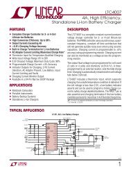
3. Block Diagram<br />
Figure 3-1. <strong>AT91</strong>SAM7S256/128/64/321 Block Diagram<br />
4<br />
TDI<br />
TDO<br />
TMS<br />
TCK<br />
JTAGSEL<br />
TST<br />
FIQ<br />
IRQ0-IRQ1<br />
PCK0-PCK2<br />
PLLRC<br />
XIN<br />
XOUT<br />
VDDCORE<br />
VDDCORE<br />
NRST<br />
DRXD<br />
DTXD<br />
RXD0<br />
TXD0<br />
SCK0<br />
RTS0<br />
CTS0<br />
RXD1<br />
TXD1<br />
SCK1<br />
RTS1<br />
CTS1<br />
DCD1<br />
DSR1<br />
DTR1<br />
RI1<br />
NPCS0<br />
NPCS1<br />
NPCS2<br />
NPCS3<br />
MISO<br />
MOSI<br />
SPCK<br />
ADTRG<br />
AD0<br />
AD1<br />
AD2<br />
AD3<br />
AD4<br />
AD5<br />
AD6<br />
AD7<br />
ADVREF<br />
PIO<br />
PLL<br />
OSC<br />
RCOSC<br />
BOD<br />
POR<br />
PIO<br />
PIO<br />
JTAG<br />
SCAN<br />
System Controller<br />
AIC<br />
PMC<br />
Reset<br />
Controller<br />
PIT<br />
WDT<br />
RTT<br />
DBGU PDC<br />
PDC<br />
PIOA<br />
<strong>ARM</strong>7TDMI<br />
Processor<br />
Peripheral Bridge<br />
Peripheral Data<br />
Controller<br />
<strong>AT91</strong>SAM7S Series Preliminary<br />
ICE<br />
USART0<br />
USART1<br />
SPI<br />
ADC<br />
Memory Controller<br />
Embedded<br />
Flash<br />
Controller<br />
PDC<br />
PDC<br />
PDC<br />
PDC<br />
PDC<br />
PDC<br />
PDC<br />
Abort<br />
Status<br />
11 Channels<br />
APB<br />
Address<br />
Decoder<br />
Misalignment<br />
Detection<br />
FIFO<br />
PDC<br />
PWMC<br />
SSC<br />
PDC<br />
Timer Counter<br />
TC0<br />
TC1<br />
TC2<br />
TWI<br />
1.8 V<br />
Voltage<br />
Regulator<br />
SRAM<br />
64/32/16/8 Kbytes<br />
Flash<br />
256/128/64/32 Kbytes<br />
Fast Flash<br />
Programming<br />
Interface<br />
USB Device<br />
ROM<br />
SAM-BA<br />
Transceiver<br />
PIO<br />
VDDIN<br />
GND<br />
VDDOUT<br />
VDDCORE<br />
VDDIO<br />
VDDFLASH<br />
ERASE<br />
PGMRDY<br />
PGMNVALID<br />
PGMNOE<br />
PGMCK<br />
PGMM0-PGMM3<br />
PGMD0-PGMD15<br />
PGMNCMD<br />
PGMEN0-PGMEN<br />
DDM<br />
DDP<br />
PWM0<br />
PWM1<br />
PWM2<br />
PWM3<br />
TF<br />
TK<br />
TD<br />
RD<br />
RK<br />
RF<br />
TCLK0<br />
TCLK1<br />
TCLK2<br />
TIOA0<br />
TIOB0<br />
TIOA1<br />
TIOB1<br />
TIOA2<br />
TIOB2<br />
TWD<br />
TWCK<br />
6175D–AT<strong>ARM</strong>–13-Feb-06
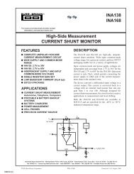
Figure 3-2. <strong>AT91</strong>SAM7S32 Block Diagram<br />
TDI<br />
TDO<br />
TMS<br />
TCK<br />
JTAGSEL<br />
TST<br />
FIQ<br />
IRQ0<br />
PCK0-PCK2<br />
PLLRC<br />
XIN<br />
XOUT<br />
VDDCORE<br />
VDDCORE<br />
NRST<br />
DRXD<br />
DTXD<br />
RXD0<br />
TXD0<br />
SCK0<br />
RTS0<br />
CTS0<br />
NPCS0<br />
NPCS1<br />
NPCS2<br />
NPCS3<br />
MISO<br />
MOSI<br />
SPCK<br />
ADTRG<br />
AD0<br />
AD1<br />
AD2<br />
AD3<br />
AD4<br />
AD5<br />
AD6<br />
AD7<br />
ADVREF<br />
6175D–AT<strong>ARM</strong>–13-Feb-06<br />
PIO<br />
PLL<br />
OSC<br />
BOD<br />
POR<br />
PIO<br />
PIO<br />
JTAG<br />
SCAN<br />
System Controller<br />
RCOSC<br />
AIC<br />
PMC<br />
Reset<br />
Controller<br />
DBGU<br />
PIT<br />
WDT<br />
RTT<br />
PIOA<br />
PDC<br />
PDC<br />
ICE<br />
USART0<br />
SPI<br />
ADC<br />
PDC<br />
PDC<br />
PDC<br />
PDC<br />
PDC<br />
Embedded<br />
Flash<br />
Controller<br />
Abort<br />
Status<br />
9 Channels<br />
APB<br />
<strong>AT91</strong>SAM7S Series Preliminary<br />
<strong>ARM</strong>7TDMI<br />
Processor<br />
Memory Controller<br />
Peripheral Bridge<br />
Peripheral DMA<br />
Controller<br />
Address<br />
Decoder<br />
Misalignment<br />
Detection<br />
PDC<br />
PDC<br />
PWMC<br />
SSC<br />
Timer Counter<br />
TC0<br />
TWI<br />
TC1<br />
TC2<br />
SRAM<br />
8 Kbytes<br />
Flash<br />
32 Kbytes<br />
ROM<br />
1.8 V<br />
Voltage<br />
Regulator<br />
Fast Flash<br />
Programming<br />
Interface<br />
SAM-BA<br />
PIO<br />
VDDIN<br />
GND<br />
VDDOUT<br />
VDDCORE<br />
VDDIO<br />
VDDFLASH<br />
ERASE<br />
PGMRDY<br />
PGMNVALID<br />
PGMNOE<br />
PGMCK<br />
PGMM0-PGMM3<br />
PGMD0-PGMD7<br />
PGMNCMD<br />
PGMEN0-PGMEN2<br />
PWM0<br />
PWM1<br />
PWM2<br />
PWM3<br />
TF<br />
TK<br />
TD<br />
RD<br />
RK<br />
RF<br />
TCLK0<br />
TIOA0<br />
TIOB0<br />
TIOA1<br />
TIOB1<br />
TWD<br />
TWCK<br />
5
4. Signal Description<br />
Table 4-1. Signal Description List<br />
Signal Name Function Type<br />
Active<br />
Level Comments<br />
VDDIN<br />
Power<br />
Voltage and ADC Regulator Power Supply Input Power 3.0 to 3.6V<br />
VDDOUT Voltage Regulator Output Power 1.85V nominal<br />
VDDFLASH Flash Power Supply Power 3.0V to 3.6V<br />
VDDIO I/O Lines Power Supply Power 3.0V to 3.6V or 1.65V to 1.95V<br />
VDDCORE Core Power Supply Power 1.65V to 1.95V<br />
VDDPLL PLL Power 1.65V to 1.95V<br />
GND Ground Ground<br />
XIN Main Oscillator Input<br />
Clocks, Oscillators and PLLs<br />
Input<br />
XOUT Main Oscillator Output Output<br />
PLLRC PLL Filter Input<br />
PCK0 - PCK2 Programmable Clock Output Output<br />
ICE and JTAG<br />
TCK Test Clock Input No pull-up resistor<br />
TDI Test Data In Input No pull-up resistor<br />
TDO Test Data Out Output<br />
TMS Test Mode Select Input No pull-up resistor<br />
JTAGSEL JTAG Selection Input<br />
Flash Memory<br />
Pull-down resistor<br />
ERASE<br />
Flash and NVM Configuration Bits Erase<br />
Command<br />
Reset/Test<br />
Input High Pull-down resistor<br />
NRST Microcontroller Reset I/O Low Open-drain with pull-Up resistor<br />
TST Test Mode Select<br />
Debug Unit<br />
Input High Pull-down resistor<br />
DRXD Debug Receive Data Input<br />
DTXD Debug Transmit Data<br />
AIC<br />
Output<br />
IRQ0 - IRQ1 External Interrupt Inputs Input<br />
FIQ Fast Interrupt Input Input<br />
PIO<br />
PA0 - PA31 Parallel IO Controller A I/O<br />
6<br />
<strong>AT91</strong>SAM7S Series Preliminary<br />
IRQ1 not present on<br />
<strong>AT91</strong>SAM7S32<br />
Pulled-up input at reset<br />
PA0 - PA20 only on <strong>AT91</strong>SAM7S32<br />
6175D–AT<strong>ARM</strong>–13-Feb-06
Table 4-1. Signal Description List (Continued)<br />
Signal Name Function Type<br />
6175D–AT<strong>ARM</strong>–13-Feb-06<br />
<strong>AT91</strong>SAM7S Series Preliminary<br />
DDM USB Device Port Data -<br />
USB Device Port<br />
Analog not present on <strong>AT91</strong>SAM7S32<br />
DDP USB Device Port Data + Analog<br />
USART<br />
not present on <strong>AT91</strong>SAM7S32<br />
SCK0 - SCK1 Serial Clock I/O<br />
TXD0 - TXD1 Transmit Data I/O<br />
RXD0 - RXD1 Receive Data Input<br />
RTS0 - RTS1 Request To Send Output<br />
CTS0 - CTS1 Clear To Send Input<br />
SCK1 not present on<br />
<strong>AT91</strong>SAM7S32<br />
TXD1 not present on<br />
<strong>AT91</strong>SAM7S32<br />
RXD1 not present on<br />
<strong>AT91</strong>SAM7S32<br />
RTS1 not present on<br />
<strong>AT91</strong>SAM7S32<br />
CTS1 not present on<br />
<strong>AT91</strong>SAM7S32<br />
DCD1 Data Carrier Detect Input not present on <strong>AT91</strong>SAM7S32<br />
DTR1 Data Terminal Ready Output not present on <strong>AT91</strong>SAM7S32<br />
DSR1 Data Set Ready Input not present on <strong>AT91</strong>SAM7S32<br />
RI1 Ring Indicator Input not present on <strong>AT91</strong>SAM7S32<br />
TD Transmit Data<br />
Synchronous Serial Controller<br />
Output<br />
RD Receive Data Input<br />
TK Transmit Clock I/O<br />
RK Receive Clock I/O<br />
TF Transmit Frame Sync I/O<br />
RF Receive Frame Sync I/O<br />
Timer/Counter<br />
TCLK0 - TCLK2 External Clock Inputs Input<br />
TIOA0 - TIOA2 I/O Line A I/O<br />
TIOB0 - TIOB2 I/O Line B I/O<br />
PWM0 - PWM3 PWM Channels<br />
PWM Controller<br />
Output<br />
SPI<br />
MISO Master In Slave Out I/O<br />
MOSI Master Out Slave In I/O<br />
SPCK SPI Serial Clock I/O<br />
NPCS0 SPI Peripheral Chip Select 0 I/O Low<br />
NPCS1-NPCS3 SPI Peripheral Chip Select 1 to 3 Output Low<br />
Active<br />
Level Comments<br />
TCLK1 and TCLK2 not present on<br />
<strong>AT91</strong>SAM7S32<br />
TIOA2 not present on<br />
<strong>AT91</strong>SAM7S32<br />
TIOB2 not present on<br />
<strong>AT91</strong>SAM7S32<br />
7
Table 4-1. Signal Description List (Continued)<br />
Signal Name Function Type<br />
TWD Two-wire Serial Data<br />
Two-Wire Interface<br />
I/O<br />
TWCK Two-wire Serial Clock I/O<br />
Analog-to-Digital Converter<br />
AD0-AD3 Analog Inputs Analog Digital pulled-up inputs at reset<br />
AD4-AD7 Analog Inputs Analog Analog Inputs<br />
ADTRG ADC Trigger Input<br />
ADVREF ADC Reference Analog<br />
Fast Flash Programming Interface<br />
PGMEN0-PGMEN2 Programming Enabling Input<br />
PGMM0-PGMM3 Programming Mode Input<br />
PGMD0-PGMD15 Programming Data I/O<br />
PGMRDY Programming Ready Output High<br />
PGMNVALID Data Direction Output Low<br />
PGMNOE Programming Read Input Low<br />
PGMCK Programming Clock Input<br />
PGMNCMD Programming Command Input Low<br />
8<br />
<strong>AT91</strong>SAM7S Series Preliminary<br />
Active<br />
Level Comments<br />
PGMD0-PGMD7 only on<br />
<strong>AT91</strong>SAM7S32<br />
6175D–AT<strong>ARM</strong>–13-Feb-06
5. Package and Pinout<br />
6175D–AT<strong>ARM</strong>–13-Feb-06<br />
<strong>AT91</strong>SAM7S Series Preliminary<br />
The <strong>AT91</strong>SAM7S256/128/64/321 are available in a 64-lead LQFP package.<br />
The <strong>AT91</strong>SAM7S32 is available in a 48-lead LQFP package.<br />
5.1 64-lead LQFP Mechanical Overview<br />
Figure 5-1 shows the orientation of the 64-lead LQFP package. A detailed mechanical<br />
description is given in the section Mechanical Characteristics of the full datasheet.<br />
5.2 64-lead LQFP Pinout<br />
Figure 5-1. 64-lead LQFP Package Pinout (Top View)<br />
Table 5-1. <strong>AT91</strong>SAM7S256/128/64/321 Pinout in 64-lead LQFP Package<br />
49<br />
64<br />
48<br />
1<br />
33<br />
32<br />
17<br />
16<br />
1 ADVREF 17 GND 33 TDI 49 TDO<br />
2 GND 18 VDDIO 34 PA6/PGMNOE 50 JTAGSEL<br />
3 AD4 19 PA16/PGMD4 35 PA5/PGMRDY 51 TMS<br />
4 AD5 20 PA15/PGMD3 36 PA4/PGMNCMD 52 PA31<br />
5 AD6 21 PA14/PGMD2 37 PA27/PGMD15 53 TCK<br />
6 AD7 22 PA13/PGMD1 38 PA28 54 VDDCORE<br />
7 VDDIN 23 PA24/PGMD12 39 NRST 55 ERASE<br />
8 VDDOUT 24 VDDCORE 40 TST 56 DDM<br />
9 PA17/PGMD5/AD0 25 PA25/PGMD13 41 PA29 57 DDP<br />
10 PA18/PGMD6/AD1 26 PA26/PGMD14 42 PA30 58 VDDIO<br />
11 PA21/PGMD9 27 PA12/PGMD0 43 PA3 59 VDDFLASH<br />
12 VDDCORE 28 PA11/PGMM3 44 PA2/PGMEN2 60 GND<br />
13 PA19/PGMD7/AD2 29 PA10/PGMM2 45 VDDIO 61 XOUT<br />
14 PA22/PGMD10 30 PA9/PGMM1 46 GND 62 XIN/PGMCK<br />
15 PA23/PGMD11 31 PA8/PGMM0 47 PA1/PGMEN1 63 PLLRC<br />
16 PA20/PGMD8/AD3 32 PA7/PGMNVALID 48 PA0/PGMEN0 64 VDDPLL<br />
9
5.3 48-lead LQFP Mechanical Overview<br />
Figure 5-1 shows the orientation of the 48-lead LQFP package. A detailed mechanical<br />
description is given in the section Mechanical Characteristics of the product datasheet.<br />
5.4 48-lead LQFP Pinout<br />
10<br />
Figure 5-2. 48-lead LQFP Package Pinout (Top View)<br />
Table 5-2. <strong>AT91</strong>SAM7S32 Pinout in 48-lead LQFP Package<br />
<strong>AT91</strong>SAM7S Series Preliminary<br />
37<br />
48<br />
36<br />
1<br />
25<br />
24<br />
13<br />
12<br />
1 ADVREF 13 VDDIO 25 TDI 37 TDO<br />
2 GND 14 PA16/PGMD4 26 PA6/PGMNOE 38 JTAGSEL<br />
3 AD4 15 PA15/PGMD3 27 PA5/PGMRDY 39 TMS<br />
4 AD5 16 PA14/PGMD2 28 PA4/PGMNCMD 40 TCK<br />
5 AD6 17 PA13/PGMD1 29 NRST 41 VDDCORE<br />
6 AD7 18 VDDCORE 30 TST 42 ERASE<br />
7 VDDIN 19 PA12/PGMD0 31 PA3 43 VDDFLASH<br />
8 VDDOUT 20 PA11/PGMM3 32 PA2/PGMEN2 44 GND<br />
9 PA17/PGMD5/AD0 21 PA10/PGMM2 33 VDDIO 45 XOUT<br />
10 PA18/PGMD6/AD1 22 PA9/PGMM1 34 GND 46 XIN/PGMCK<br />
11 PA19/PGMD7/AD2 23 PA8/PGMM0 35 PA1/PGMEN1 47 PLLRC<br />
12 PA20/AD3 24 PA7/PGMNVALID 36 PA0/PGMEN0 48 VDDPLL<br />
6175D–AT<strong>ARM</strong>–13-Feb-06
6. Power Considerations<br />
6.1 Power Supplies<br />
6.2 Power Consumption<br />
6175D–AT<strong>ARM</strong>–13-Feb-06<br />
<strong>AT91</strong>SAM7S Series Preliminary<br />
The <strong>AT91</strong>SAM7S Series has six types of power supply pins and integrates a voltage regulator,<br />
allowing the device to be supplied with only one voltage. The six power supply pin types are:<br />
VDDIN pin. It powers the voltage regulator and the ADC; voltage ranges from 3.0V to 3.6V,<br />
3.3V nominal.<br />
VDDOUT pin. It is the output of the 1.8V voltage regulator.<br />
VDDIO pin. It powers the I/O lines and the USB transceivers; dual voltage range is<br />
supported. Ranges from 3.0V to 3.6V, 3.3V nominal or from 1.65V to 1.95V, 1.8V nominal.<br />
Note that supplying less than 3.0V to VDDIO prevents any use of the USB transceivers.<br />
VDDFLASH pin. It powers a part of the Flash and is required for the Flash to operate<br />
correctly; voltage ranges from 3.0V to 3.6V, 3.3V nominal.<br />
VDDCORE pins. They power the logic of the device; voltage ranges from 1.65V to 1.95V,<br />
1.8V typical. It can be connected to the VDDOUT pin with decoupling capacitor.<br />
VDDCORE is required for the device, including its embedded Flash, to operate correctly.<br />
During startup, core supply voltage (VDDCORE) slope must be superior or equal to<br />
6V/ms.<br />
VDDPLL pin. It powers the oscillator and the PLL. It can be connected directly to the<br />
VDDOUT pin.<br />
No separate ground pins are provided for the different power supplies. Only GND pins are provided<br />
and should be connected as shortly as possible to the system ground plane.<br />
In order to decrease current consumption, if the voltage regulator and the ADC are not used,<br />
VDDIN, ADVREF, AD4, AD5, AD6 and AD7 should be connected to GND. In this case<br />
VDDOUT should be left unconnected.<br />
The <strong>AT91</strong>SAM7S Series has a static current of less than 60 µA on VDDCORE at 25°C, including<br />
the RC oscillator, the voltage regulator and the power-on reset. When the brown-out<br />
detector is activated, 20 µA static current is added.<br />
The dynamic power consumption on VDDCORE is less than 50 mA at full speed when running<br />
out of the Flash. Under the same conditions, the power consumption on VDDFLASH does not<br />
exceed 10 mA.<br />
6.3 Voltage Regulator<br />
The <strong>AT91</strong>SAM7S Series embeds a voltage regulator that is managed by the System<br />
Controller.<br />
In Normal Mode, the voltage regulator consumes less than 100 µA static current and draws<br />
100 mA of output current.<br />
The voltage regulator also has a Low-power Mode. In this mode, it consumes less than 25 µA<br />
static current and draws 1 mA of output current.<br />
Adequate output supply decoupling is mandatory for VDDOUT to reduce ripple and avoid<br />
oscillations. The best way to achieve this is to use two capacitors in parallel: one external 470<br />
11
12<br />
pF (or 1 nF) NPO capacitor must be connected between VDDOUT and GND as close to the<br />
chip as possible. One external 2.2 µF (or 3.3 µF) X7R capacitor must be connected between<br />
VDDOUT and GND.<br />
Adequate input supply decoupling is mandatory for VDDIN in order to improve startup stability<br />
and reduce source voltage drop. The input decoupling capacitor should be placed close to the<br />
chip. For example, two capacitors can be used in parallel: 100 nF NPO and 4.7 µF X7R.<br />
6.4 Typical Powering Schematics<br />
The <strong>AT91</strong>SAM7S Series supports a 3.3V single supply mode. The internal regulator is connected<br />
to the 3.3V source and its output feeds VDDCORE and the VDDPLL. Figure 6-1 shows<br />
the power schematics to be used for USB bus-powered systems.<br />
Figure 6-1. 3.3V System Single Power Supply Schematic<br />
Power Source<br />
ranges<br />
from 4.5V (USB)<br />
to 18V<br />
DC/DC Converter<br />
<strong>AT91</strong>SAM7S Series Preliminary<br />
3.3V<br />
VDDFLASH<br />
VDDIO<br />
VDDIN<br />
VDDOUT<br />
VDDCORE<br />
VDDPLL<br />
Voltage<br />
Regulator<br />
6175D–AT<strong>ARM</strong>–13-Feb-06
7. I/O Lines Considerations<br />
7.1 JTAG Port Pins<br />
7.2 Test Pin<br />
7.3 Reset Pin<br />
7.4 ERASE Pin<br />
6175D–AT<strong>ARM</strong>–13-Feb-06<br />
<strong>AT91</strong>SAM7S Series Preliminary<br />
TMS, TDI and TCK are schmitt trigger inputs. TMS and TCK are 5-V tolerant, TDI is not. TMS,<br />
TDI and TCK do not integrate a pull-up resistor.<br />
TDO is an output, driven at up to VDDIO, and has no pull-up resistor.<br />
The JTAGSEL pin is used to select the JTAG boundary scan when asserted at a high level.<br />
The JTAGSEL pin integrates a permanent pull-down resistor of about 15 kΩ to GND, so that it<br />
can be left unconnected for normal operations.<br />
The TST pin is used for manufacturing test, fast programming mode or SAM-BA Boot Recovery<br />
of the <strong>AT91</strong>SAM7S Series when asserted high. The TST pin integrates a permanent pulldown<br />
resistor of about 15 kΩ to GND, so that it can be left unconnected for normal operations.<br />
To enter fast programming mode, the TST pin and the PA0 and PA1 pins should be tied high<br />
and PA2 tied to low.<br />
To enter SAM-BA Boot Recovery, the TST pin and the PA0, PA1 and PA2 pins should be tied<br />
high.<br />
Driving the TST pin at a high level while PA0 or PA1 is driven at 0 leads to unpredictable<br />
results.<br />
The NRST pin is bidirectional with an open drain output buffer. It is handled by the on-chip<br />
reset controller and can be driven low to provide a reset signal to the external components or<br />
asserted low externally to reset the microcontroller. There is no constraint on the length of the<br />
reset pulse, and the reset controller can guarantee a minimum pulse length. This allows connection<br />
of a simple push-button on the pin NRST as system user reset, and the use of the<br />
signal NRST to reset all the components of the system.<br />
The NRST pin integrates a permanent pull-up resistor to VDDIO.<br />
The ERASE pin is used to re-initialize the Flash content and some of its NVM bits. It integrates<br />
a permanent pull-down resistor of about 15 kΩ to GND, so that it can be left unconnected for<br />
normal operations.<br />
7.5 PIO Controller A Lines<br />
All the I/O lines PA0 to PA31 (PA0 to PA20 on <strong>AT91</strong>SAM7S32) are 5V-tolerant and all integrate<br />
a programmable pull-up resistor. Programming of this pull-up resistor is performed<br />
independently for each I/O line through the PIO controllers.<br />
5V-tolerant means that the I/O lines can drive voltage level according to VDDIO, but can be<br />
driven with a voltage of up to 5.5V. However, driving an I/O line with a voltage over VDDIO<br />
while the programmable pull-up resistor is enabled will create a current path through the pullup<br />
resistor from the I/O line to VDDIO. Care should be taken, in particular at reset, as all the<br />
I/O lines default to input with pull-up resistor enabled at reset.<br />
13
7.6 I/O Line Drive Levels<br />
The PIO lines PA0 to PA3 are high-drive current capable. Each of these I/O lines can drive up<br />
to 16 mA permanently.<br />
14<br />
The remaining I/O lines can draw only 8 mA.<br />
However, the total current drawn by all the I/O lines cannot exceed 150 mA (100mA for<br />
<strong>AT91</strong>SAM7S32).<br />
<strong>AT91</strong>SAM7S Series Preliminary<br />
6175D–AT<strong>ARM</strong>–13-Feb-06
8. Processor and Architecture<br />
8.1 <strong>ARM</strong>7TDMI Processor<br />
8.2 Debug and Test Features<br />
8.3 Memory Controller<br />
6175D–AT<strong>ARM</strong>–13-Feb-06<br />
<strong>AT91</strong>SAM7S Series Preliminary<br />
RISC processor <strong>based</strong> on <strong>ARM</strong>v4T Von Neumann architecture<br />
– Runs at up to 55 MHz, providing 0.9 MIPS/MHz<br />
Two instruction sets<br />
–<strong>ARM</strong> ® high-performance 32-bit instruction set<br />
–<strong>Thumb</strong> ® high code density 16-bit instruction set<br />
Three-stage pipeline architecture<br />
– Instruction Fetch (F)<br />
– Instruction Decode (D)<br />
– Execute (E)<br />
Integrated EmbeddedICE (embedded in-circuit emulator)<br />
– Two watchpoint units<br />
– Test access port accessible through a JTAG protocol<br />
– Debug communication channel<br />
Debug Unit<br />
–Two-pin UART<br />
– Debug communication channel interrupt handling<br />
– Chip ID Register<br />
IEEE1149.1 JTAG Boundary-scan on all digital pins<br />
Bus Arbiter<br />
– Handles requests from the <strong>ARM</strong>7TDMI and the Peripheral DMA Controller<br />
Address decoder provides selection signals for<br />
– Three internal 1 Mbyte memory areas<br />
– One 256 Mbyte embedded peripheral area<br />
Abort Status Registers<br />
– Source, Type and all parameters of the access leading to an abort are saved<br />
– Facilitates debug by detection of bad pointers<br />
Misalignment Detector<br />
– Alignment checking of all data accesses<br />
– Abort generation in case of misalignment<br />
Remap Command<br />
– Remaps the SRAM in place of the embedded non-volatile memory<br />
– Allows handling of dynamic exception vectors<br />
Embedded Flash Controller<br />
– Embedded Flash interface, up to three programmable wait states<br />
15
8.4 Peripheral DMA Controller<br />
16<br />
– Prefetch buffer, buffering and anticipating the 16-bit requests, reducing the<br />
required wait states<br />
– Key-protected program, erase and lock/unlock sequencer<br />
– Single command for erasing, programming and locking operations<br />
– Interrupt generation in case of forbidden operation<br />
Handles data transfer between peripherals and memories<br />
Eleven channels: <strong>AT91</strong>SAM7S256/128/64/321<br />
Nine channels: <strong>AT91</strong>SAM7S32<br />
– Two for each USART<br />
– Two for the Debug Unit<br />
– Two for the Serial Synchronous Controller<br />
– Two for the Serial Peripheral Interface<br />
– One for the Analog-to-digital Converter<br />
Low bus arbitration overhead<br />
– One Master Clock cycle needed for a transfer from memory to peripheral<br />
– Two Master Clock cycles needed for a transfer from peripheral to memory<br />
Next Pointer management for reducing interrupt latency requirements<br />
<strong>AT91</strong>SAM7S Series Preliminary<br />
6175D–AT<strong>ARM</strong>–13-Feb-06
9. Memory<br />
9.1 <strong>AT91</strong>SAM7S256<br />
9.2 <strong>AT91</strong>SAM7S128<br />
9.3 <strong>AT91</strong>SAM7S64<br />
6175D–AT<strong>ARM</strong>–13-Feb-06<br />
256 Kbytes of Flash Memory single plane<br />
– 1024 pages of 256 bytes<br />
<strong>AT91</strong>SAM7S Series Preliminary<br />
– Fast access time, 30 MHz single-cycle access in Worst Case conditions<br />
– Page programming time: 6 ms, including page auto-erase<br />
– Page programming without auto-erase: 3 ms<br />
– Full chip erase time: 15 ms<br />
– 10,000 write cycles, 10-year data retention capability<br />
– 16 lock bits, protecting 16 sectors of 64 pages<br />
– Protection Mode to secure contents of the Flash<br />
64 Kbytes of Fast SRAM<br />
– Single-cycle access at full speed<br />
128 Kbytes of Flash Memory single plane<br />
– 512 pages of 256 bytes<br />
– Fast access time, 30 MHz single-cycle access in Worst Case conditions<br />
– Page programming time: 6 ms, including page auto-erase<br />
– Page programming without auto-erase: 3 ms<br />
– Full chip erase time: 15 ms<br />
– 10,000 write cycles, 10-year data retention capability<br />
– 8 lock bits, protecting 8 sectors of 64 pages<br />
– Protection Mode to secure contents of the Flash<br />
32 Kbytes of Fast SRAM<br />
– Single-cycle access at full speed<br />
64 Kbytes of Flash Memory single plane<br />
– 512 pages of 128 bytes<br />
– Fast access time, 30 MHz single-cycle access in Worst Case conditions<br />
– Page programming time: 6 ms, including page auto-erase<br />
– Page programming without auto-erase: 3 ms<br />
– Full chip erase time: 15 ms<br />
– 10,000 write cycles, 10-year data retention capability<br />
– 16 lock bits, protecting 16 sectors of 32 pages<br />
– Protection Mode to secure contents of the Flash<br />
16 Kbytes of Fast SRAM<br />
– Single-cycle access at full speed<br />
17
9.4 <strong>AT91</strong>SAM7S321/32<br />
9.5 Memory Mapping<br />
9.5.1 Internal SRAM<br />
9.5.2 Internal ROM<br />
9.5.3 Internal Flash<br />
18<br />
32 Kbytes of Flash Memory single plane<br />
– 256 pages of 128 bytes<br />
– Fast access time, 30 MHz single-cycle access in Worst Case conditions<br />
– Page programming time: 6 ms, including page auto-erase<br />
– Page programming without auto-erase: 3 ms<br />
– Full chip erase time: 15 ms<br />
– 10,000 write cycles, 10-year data retention capability<br />
– 8 lock bits, protecting 8 sectors of 32 pages<br />
– Protection Mode to secure contents of the Flash<br />
8 Kbytes of Fast SRAM<br />
– Single-cycle access at full speed<br />
The <strong>AT91</strong>SAM7S256/128/64/321/32 embeds a high-speed 64/32/16/8/8-Kbyte SRAM bank.<br />
After reset and until the Remap Command is performed, the SRAM is only accessible at<br />
address 0x0020 0000. After Remap, the SRAM also becomes available at address 0x0.<br />
The <strong>AT91</strong>SAM7S Series embeds an Internal ROM. The ROM contains the FFPI and the<br />
SAM-BA program.<br />
The internal ROM is not mapped by default.<br />
The <strong>AT91</strong>SAM7S256/128/64/321/32 features one bank of 256/128/64/32/32 Kbytes of Flash.<br />
At any time, the Flash is mapped to address 0x0010 0000. It is also accessible at address 0x0<br />
after the reset and before the Remap Command.<br />
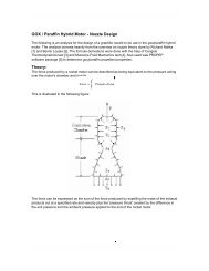
Figure 9-1. Internal Memory Mapping<br />
256M Bytes<br />
0x0000 0000<br />
0x000F FFFF<br />
0x0010 0000<br />
0x001F FFFF<br />
0x0020 0000<br />
0x002F FFFF<br />
0x0030 0000<br />
0x0FFF FFFF<br />
<strong>AT91</strong>SAM7S Series Preliminary<br />
Flash Before Remap<br />
SRAM After Remap<br />
Internal Flash<br />
Internal SRAM<br />
Undefined Areas<br />
(Abort)<br />
1 M Bytes<br />
1 M Bytes<br />
1 M Bytes<br />
253 M Bytes<br />
6175D–AT<strong>ARM</strong>–13-Feb-06
9.6 Embedded Flash<br />
6175D–AT<strong>ARM</strong>–13-Feb-06<br />
<strong>AT91</strong>SAM7S Series Preliminary<br />
9.6.1 Flash Overview<br />
The Flash of the <strong>AT91</strong>SAM7S256 is organized in 1024 pages of 256 bytes. The 262,144<br />
bytes are organized in 32-bit words.<br />
The Flash of the <strong>AT91</strong>SAM7S128 is organized in 512 pages of 256 bytes. The 131,072<br />
bytes are organized in 32-bit words.<br />
The Flash of the <strong>AT91</strong>SAM7S64 is organized in 512 pages of 128 bytes. The 65,536 bytes<br />
are organized in 32-bit words.<br />
The Flash of the <strong>AT91</strong>SAM7S321/32 is organized in 256 pages of 128 bytes. The 32,768<br />
bytes are organized in 32-bit words.<br />
The Flash of the <strong>AT91</strong>SAM7S256/128 contains a 256-byte write buffer, accessible through<br />
a 32-bit interface.<br />
The Flash of the <strong>AT91</strong>SAM7S64/321/32 contains a 128-byte write buffer, accessible<br />
through a 32-bit interface.<br />
The Flash benefits from the integration of a power reset cell and from the brownout detector.<br />
This prevents code corruption during power supply changes, even in the worst conditions.<br />
When Flash is not used (read or write access), it is automatically placed into standby mode.<br />
9.6.2 Embedded Flash Controller<br />
The Embedded Flash Controller (EFC) manages accesses performed by the masters of the<br />
system. It enables reading the Flash and writing the write buffer. It also contains a User Interface,<br />
mapped within the Memory Controller on the APB. The User Interface allows:<br />
9.6.3 Lock Regions<br />
Table 9-1. Flash Configuration Summary<br />
programming of the access parameters of the Flash (number of wait states, timings, etc.)<br />
starting commands such as full erase, page erase, page program, NVM bit set, NVM bit<br />
clear, etc.<br />
getting the end status of the last command<br />
getting error status<br />
programming interrupts on the end of the last commands or on errors<br />
The Embedded Flash Controller also provides a dual 32-bit Prefetch Buffer that optimizes 16bit<br />
access to the Flash. This is particularly efficient when the processor is running in <strong>Thumb</strong><br />
mode.<br />
The Embedded Flash Controller manages 16/8 lock bits to protect 16/8 regions of the flash<br />
against inadvertent flash erasing or programming commands.<br />
Table 9-1 summarizes the configuration of the five devices.<br />
Device Number of Lock Bits Number of Pages in the Lock Region Page Size<br />
<strong>AT91</strong>SAM7S256 16 64 256 bytes<br />
<strong>AT91</strong>SAM7S128 8 64 256 bytes<br />
<strong>AT91</strong>SAM7S64 16 32 128 bytes<br />
<strong>AT91</strong>SAM7S321/32 8 32 128 bytes<br />
19
20<br />
If a locked-regions erase or program command occurs, the command is aborted and the EFC<br />
trigs an interrupt.<br />
The 16 NVM bits are software programmable through the EFC User Interface. The command<br />
“Set Lock Bit” enables the protection. The command “Clear Lock Bit” unlocks the lock region.<br />
Asserting the ERASE pin clears the lock bits, thus unlocking the entire Flash.<br />
9.6.4 Security Bit Feature<br />
The <strong>AT91</strong>SAM7S Series features a security bit, <strong>based</strong> on a specific NVM-Bit. When the security<br />
is enabled, any access to the Flash, either through the ICE interface or through the Fast<br />
Flash Programming Interface, is forbidden. This ensures the confidentiality of the code programmed<br />
in the Flash.<br />
This security bit can only be enabled, through the Command “Set Security Bit” of the EFC<br />
User Interface. Disabling the security bit can only be achieved by asserting the ERASE pin at<br />
1, and after a full flash erase is performed. When the security bit is deactivated, all accesses to<br />
the flash are permitted.<br />
It is important to note that the assertion of the ERASE pin should always be longer than<br />
50 ms.<br />
As the ERASE pin integrates a permanent pull-down, it can be left unconnected during normal<br />
operation. However, it is safer to connect it directly to GND for the final application.<br />
9.6.5 Non-volatile Brownout Detector Control<br />
Two general purpose NVM (GPNVM) bits are used for controlling the brownout detector<br />
(BOD), so that even after a power loss, the brownout detector operations remain in their state.<br />
9.6.6 Calibration Bits<br />
These two GPNVM bits can be cleared or set respectively through the commands “Clear General-purpose<br />
NVM Bit” and “Set General-purpose NVM Bit” of the EFC User Interface.<br />
GPNVM Bit 0 is used as a brownout detector enable bit. Setting the GPNVM Bit 0 enables<br />
the BOD, clearing it disables the BOD. Asserting ERASE clears the GPNVM Bit 0 and thus<br />
disables the brownout detector by default.<br />
The GPNVM Bit 1 is used as a brownout reset enable signal for the reset controller. Setting<br />
the GPNVM Bit 1 enables the brownout reset when a brownout is detected, Clearing the<br />
GPNVM Bit 1 disables the brownout reset. Asserting ERASE disables the brownout reset<br />
by default.<br />
Eight NVM bits are used to calibrate the brownout detector and the voltage regulator. These<br />
bits are factory configured and cannot be changed by the user. The ERASE pin has no effect<br />
on the calibration bits.<br />
9.7 Fast Flash Programming Interface<br />
The Fast Flash Programming Interface allows programming the device through either a serial<br />
JTAG interface or through a multiplexed fully-handshaked parallel port. It allows gang-programming<br />
with market-standard industrial programmers.<br />
The FFPI supports read, page program, page erase, full erase, lock, unlock and protect<br />
commands.<br />
The Fast Flash Programming Interface is enabled and the Fast Programming Mode is entered<br />
when the TST pin and the PA0 and PA1 pins are all tied high and PA2 is tied low.<br />
<strong>AT91</strong>SAM7S Series Preliminary<br />
6175D–AT<strong>ARM</strong>–13-Feb-06
9.8 SAM-BA Boot Assistant<br />
6175D–AT<strong>ARM</strong>–13-Feb-06<br />
<strong>AT91</strong>SAM7S Series Preliminary<br />
The SAM-BA Boot Recovery restores the SAM-BA Boot in the first two sectors of the on-chip<br />
Flash memory. The SAM-BA Boot recovery is performed when the TST pin and the PA0, PA1<br />
and PA2 pins are all tied high.<br />
The SAM-BA Boot Assistant is a default Boot Program that provides an easy way to program<br />
in situ the on-chip Flash memory.<br />
The SAM-BA Boot Assistant supports serial communication through the DBGU or through the<br />
USB Device Port. (The <strong>AT91</strong>SAM7S32 has no USB Device Port.)<br />
Communication through the DBGU supports a wide range of crystals from 3 to 20 MHz via<br />
software auto-detection.<br />
Communication through the USB Device Port is limited to an 18.432 MHz crystal. (<br />
The SAM-BA Boot provides an interface with SAM-BA Graphic User Interface (GUI).<br />
21
10. System Controller<br />
22<br />
The System Controller manages all vital blocks of the microcontroller: interrupts, clocks,<br />
power, time, debug and reset.<br />
Figure 10-1. System Controller Block Diagram (<strong>AT91</strong>SAM7S256/128/64/321)<br />
NRST<br />
XIN<br />
XOUT<br />
PLLRC<br />
PA0-PA31<br />
en<br />
BOD<br />
POR<br />
RCOSC<br />
OSC<br />
PLL<br />
irq0-irq1<br />
fiq<br />
periph_irq[2..14]<br />
pit_irq<br />
rtt_irq<br />
wdt_irq<br />
dbgu_irq<br />
pmc_irq<br />
rstc_irq<br />
MCK<br />
periph_nreset<br />
dbgu_rxd<br />
MCK<br />
debug<br />
periph_nreset<br />
SLCK<br />
periph_nreset<br />
SLCK<br />
debug<br />
idle<br />
proc_nreset<br />
cal<br />
gpnvm[0]<br />
SLCK<br />
SLCK<br />
MAINCK<br />
PLLCK<br />
int<br />
periph_nreset<br />
usb_suspend<br />
periph_nreset<br />
periph_clk[2]<br />
dbgu_rxd<br />
flash_wrdis<br />
ice_nreset<br />
jtag_nreset<br />
flash_poe<br />
gpnvm[1]<br />
System Controller<br />
Advanced<br />
Interrupt<br />
Controller<br />
Debug<br />
Unit<br />
Periodic<br />
Interval<br />
Timer<br />
Real-Time<br />
Timer<br />
Watchdog<br />
Timer<br />
bod_rst_en<br />
Reset<br />
Controller<br />
Power<br />
Management<br />
Controller<br />
PIO<br />
Controller<br />
wdt_fault<br />
WDRPROC<br />
pit_irq<br />
rtt_irq<br />
wdt_irq<br />
periph_nreset<br />
proc_nreset<br />
periph_clk[2..14]<br />
pck[0-2]<br />
periph_irq{2]<br />
<strong>AT91</strong>SAM7S Series Preliminary<br />
int<br />
dbgu_irq<br />
force_ntrst<br />
dbgu_txd<br />
rstc_irq<br />
PCK<br />
UDPCK<br />
MCK<br />
pmc_irq<br />
idle<br />
irq0-irq1<br />
fiq<br />
dbgu_txd<br />
Voltage<br />
Regulator<br />
Mode<br />
Controller<br />
jtag_nreset<br />
in<br />
out<br />
enable<br />
nirq<br />
nfiq<br />
proc_nreset<br />
PCK<br />
debug<br />
ice_nreset<br />
force_ntrst<br />
flash_poe<br />
flash_wrdis<br />
cal<br />
gpnvm[0..1]<br />
MCK<br />
proc_nreset<br />
standby<br />
cal<br />
security_bit<br />
UDPCK<br />
periph_clk[11]<br />
periph_nreset<br />
periph_irq[11]<br />
usb_suspend<br />
periph_clk[4..14]<br />
periph_nreset<br />
periph_irq[4..14]<br />
Boundary Scan<br />
TAP Controller<br />
<strong>ARM</strong>7TDMI<br />
Embedded<br />
Flash<br />
Memory<br />
Controller<br />
Voltage<br />
Regulator<br />
USB Device<br />
Port<br />
Embedded<br />
Peripherals<br />
6175D–AT<strong>ARM</strong>–13-Feb-06
23<br />
6175D–AT<strong>ARM</strong>–13-Feb-06<br />
<strong>AT91</strong>SAM7S Series Preliminary<br />
Figure 10-2. System Controller Block Diagram (<strong>AT91</strong>SAM7S32)<br />
NRST<br />
SLCK<br />
Advanced<br />
Interrupt<br />
Controller<br />
Real-Time<br />
Timer<br />
Periodic<br />
Interval<br />
Timer<br />
Reset<br />
Controller<br />
PA0-PA20<br />
periph_nreset<br />
System Controller<br />
Watchdog<br />
Timer<br />
wdt_fault<br />
WDRPROC<br />
PIO<br />
Controller<br />
POR<br />
BOD<br />
RCOSC<br />
gpnvm[0]<br />
cal<br />
en<br />
Power<br />
Management<br />
Controller<br />
OSC<br />
PLL<br />
XIN<br />
XOUT<br />
PLLRC<br />
MAINCK<br />
PLLCK<br />
pit_irq<br />
MCK<br />
proc_nreset<br />
wdt_irq<br />
periph_irq{2]<br />
periph_nreset<br />
periph_clk[2..14]<br />
PCK<br />
MCK<br />
pmc_irq<br />
nirq<br />
nfiq<br />
rtt_irq<br />
Embedded<br />
Peripherals<br />
periph_clk[2]<br />
pck[0-2]<br />
in<br />
out<br />
enable<br />
<strong>ARM</strong>7TDMI<br />
SLCK<br />
SLCK<br />
irq0<br />
fiq<br />
irq0<br />
fiq<br />
periph_irq[4..14]<br />
periph_irq[2..14]<br />
int<br />
int<br />
periph_nreset<br />
periph_clk[4..14]<br />
Embedded<br />
Flash<br />
flash_poe<br />
jtag_nreset<br />
flash_poe<br />
gpnvm[0..1]<br />
flash_wrdis<br />
flash_wrdis<br />
proc_nreset<br />
periph_nreset<br />
dbgu_txd<br />
dbgu_rxd<br />
pit_irq<br />
rtt_irq<br />
dbgu_irq<br />
pmc_irq<br />
rstc_irq<br />
wdt_irq<br />
rstc_irq<br />
SLCK<br />
gpnvm[1]<br />
Boundary Scan<br />
TAP Controller<br />
jtag_nreset<br />
ice_nreset<br />
debug<br />
PCK<br />
debug<br />
idle<br />
debug<br />
Memory<br />
Controller<br />
MCK<br />
proc_nreset<br />
bod_rst_en<br />
proc_nreset<br />
periph_nreset<br />
periph_nreset<br />
idle<br />
Debug<br />
Unit<br />
dbgu_irq<br />
MCK<br />
dbgu_rxd<br />
periph_nreset<br />
force_ntrst<br />
dbgu_txd<br />
Voltage<br />
Regulator<br />
standby<br />
Voltage<br />
Regulator<br />
Mode<br />
Controller<br />
security_bit<br />
cal<br />
ice_nreset<br />
force_ntrst<br />
cal
10.1 System Controller Mapping<br />
The System Controller peripherals are all mapped to the highest 4 Kbytes of address space,<br />
between addresses 0xFFFF F000 and 0xFFFF FFFF.<br />
24<br />
Figure 10-3 shows the mapping of the System Controller. Note that the Memory Controller<br />
configuration user interface is also mapped within this address space.<br />
Figure 10-3. System Controller Mapping<br />
Address Peripheral<br />
0xFFFF F000<br />
0xFFFF F1FF<br />
0xFFFF F200<br />
0xFFFF F3FF<br />
0xFFFF F400<br />
0xFFFF F5FF<br />
0xFFFF F600<br />
0xFFFF FBFF<br />
0xFFFF FC00<br />
0xFFFF FCFF<br />
0xFFFF FD00<br />
0xFFFF FD0F<br />
0xFFFF FD20<br />
0xFFFF FC2F<br />
0xFFFF FD30<br />
0xFFFF FC3F<br />
0xFFFF FD40<br />
0xFFFF FD4F<br />
0xFFFF FD60<br />
0xFFFF FC6F<br />
0xFFFF FD70<br />
0xFFFF FEFF<br />
0xFFFF FF00<br />
0xFFFF FFFF<br />
AIC<br />
DBGU<br />
PIOA<br />
Reserved<br />
PMC<br />
RSTC<br />
Reserved<br />
RTT<br />
MC<br />
<strong>AT91</strong>SAM7S Series Preliminary<br />
PIT<br />
WDT<br />
Reserved<br />
VREG<br />
Reserved<br />
Peripheral Name Size<br />
Advanced Interrupt Controller<br />
Debug Unit<br />
PIO Controller A<br />
Power Management Controller<br />
Reset Controller<br />
Real-time Timer<br />
Periodic Interval Timer<br />
Watchdog Timer<br />
Voltage Regulator Mode Controller<br />
Memory Controller<br />
512 Bytes/128 registers<br />
512 Bytes/128 registers<br />
512 Bytes/128 registers<br />
256 Bytes/64 registers<br />
16 Bytes/4 registers<br />
16 Bytes/4 registers<br />
16 Bytes/4 registers<br />
16 Bytes/4 registers<br />
4 Bytes/1 register<br />
256 Bytes/64 registers<br />
6175D–AT<strong>ARM</strong>–13-Feb-06
6175D–AT<strong>ARM</strong>–13-Feb-06<br />
<strong>AT91</strong>SAM7S Series Preliminary<br />
10.2 Reset Controller<br />
The Reset Controller is <strong>based</strong> on a power-on reset cell and one brownout detector. It gives the<br />
status of the last reset, indicating whether it is a power-up reset, a software reset, a user reset,<br />
a watchdog reset or a brownout reset. In addition, it controls the internal resets and the NRST<br />
pin open-drain output. It allows to shape a signal on the NRST line, guaranteeing that the<br />
length of the pulse meets any requirement.<br />
Note that if NRST is used as a reset output signal for external devices during power-off, the<br />
brownout detector must be activated.<br />
10.2.1 Brownout Detector and Power-on Reset<br />
The <strong>AT91</strong>SAM7S Series embeds a brownout detection circuit and a power-on reset cell. Both<br />
are supplied with and monitor VDDCORE. Both signals are provided to the Flash to prevent<br />
any code corruption during power-up or power-down sequences or if brownouts occur on the<br />
VDDCORE power supply.<br />
The power-on reset cell has a limited-accuracy threshold at around 1.5V. Its output remains<br />
low during power-up until VDDCORE goes over this voltage level. This signal goes to the reset<br />
controller and allows a full re-initialization of the device.<br />
The brownout detector monitors the VDDCORE level during operation by comparing it to a<br />
fixed trigger level. It secures system operations in the most difficult environments and prevents<br />
code corruption in case of brownout on the VDDCORE.<br />
Only VDDCORE is monitored, as a voltage drop on VDDFLASH or any other power supply of<br />
the device cannot affect the Flash.<br />
When the brownout detector is enabled and VDDCORE decreases to a value below the trigger<br />
level (Vbot-, defined as Vbot - hyst/2), the brownout output is immediately activated.<br />
When VDDCORE increases above the trigger level (Vbot+, defined as Vbot + hyst/2), the<br />
reset is released. The brownout detector only detects a drop if the voltage on VDDCORE<br />
stays below the threshold voltage for longer than about 1µs.<br />
The threshold voltage has a hysteresis of about 50 mV, to ensure spike free brownout detection.<br />
The typical value of the brownout detector threshold is 1.68V with an accuracy of ± 2%<br />
and is factory calibrated.<br />
The brownout detector is low-power, as it consumes less than 20 µA static current. However, it<br />
can be deactivated to save its static current. In this case, it consumes less than 1µA. The<br />
deactivation is configured through the GPNVM bit 0 of the Flash.<br />
25
10.3 Clock Generator<br />
The Clock Generator embeds one low-power RC Oscillator, one Main Oscillator and one PLL<br />
with the following characteristics:<br />
26<br />
RC Oscillator ranges between 22 kHz and 42 kHz<br />
Main Oscillator frequency ranges between 3 and 20 MHz<br />
Main Oscillator can be bypassed<br />
PLL output ranges between 80 and 220 MHz<br />
It provides SLCK, MAINCK and PLLCK.<br />
Figure 10-4. Clock Generator Block Diagram<br />
<strong>AT91</strong>SAM7S Series Preliminary<br />
XIN<br />
XOUT<br />
PLLRC<br />
Clock Generator<br />
Embedded<br />
RC<br />
Oscillator<br />
Main<br />
Oscillator<br />
PLL and<br />
Divider<br />
Status<br />
Power<br />
Management<br />
Controller<br />
Control<br />
Slow Clock<br />
SLCK<br />
Main Clock<br />
MAINCK<br />
PLL Clock<br />
PLLCK<br />
6175D–AT<strong>ARM</strong>–13-Feb-06
6175D–AT<strong>ARM</strong>–13-Feb-06<br />
<strong>AT91</strong>SAM7S Series Preliminary<br />
10.4 Power Management Controller<br />
The Power Management Controller uses the Clock Generator outputs to provide:<br />
10.5 Advanced Interrupt Controller<br />
the Processor Clock PCK<br />
the Master Clock MCK<br />
the USB Clock UDPCK (not present on <strong>AT91</strong>SAM7S32)<br />
all the peripheral clocks, independently controllable<br />
three programmable clock outputs<br />
The Master Clock (MCK) is programmable from a few hundred Hz to the maximum operating<br />
frequency of the device.<br />
The Processor Clock (PCK) switches off when entering processor idle mode, thus allowing<br />
reduced power consumption while waiting for an interrupt.<br />
Figure 10-5. Power Management Controller Block Diagram<br />
SLCK<br />
MAINCK<br />
PLLCK<br />
SLCK<br />
MAINCK<br />
PLLCK<br />
PLLCK<br />
Master Clock Controller<br />
Prescaler<br />
/1,/2,/4,...,/64<br />
Programmable Clock Controller<br />
Prescaler<br />
/1,/2,/4,...,/64<br />
USB Clock Controller<br />
ON/OFF<br />
Divider<br />
/1,/2,/4<br />
Processor<br />
Clock<br />
Controller<br />
Idle Mode<br />
Peripherals<br />
Clock Controller<br />
ON/OFF<br />
Controls the interrupt lines (nIRQ and nFIQ) of an <strong>ARM</strong> Processor<br />
Individually maskable and vectored interrupt sources<br />
– Source 0 is reserved for the Fast Interrupt Input (FIQ)<br />
– Source 1 is reserved for system peripherals RTT, PIT, EFC, PMC, DBGU, etc.)<br />
– Other sources control the peripheral interrupts or external interrupts<br />
– Programmable edge-triggered or level-sensitive internal sources<br />
– Programmable positive/negative edge-triggered or high/low level-sensitive<br />
external sources<br />
8-level Priority Controller<br />
– Drives the normal interrupt of the processor<br />
– Handles priority of the interrupt sources<br />
PCK<br />
int<br />
MCK<br />
periph_clk[2..14]<br />
pck[0..2]<br />
usb_suspend<br />
UDPCK<br />
27
10.6 Debug Unit<br />
10.7 Periodic Interval Timer<br />
10.8 Watchdog Timer<br />
28<br />
– Higher priority interrupts can be served during service of lower priority interrupt<br />
Vectoring<br />
– Optimizes interrupt service routine branch and execution<br />
– One 32-bit vector register per interrupt source<br />
– Interrupt vector register reads the corresponding current interrupt vector<br />
Protect Mode<br />
– Easy debugging by preventing automatic operations<br />
Fast Forcing<br />
– Permits redirecting any interrupt source on the fast interrupt<br />
General Interrupt Mask<br />
– Provides processor synchronization on events without triggering an interrupt<br />
Comprises:<br />
– One two-pin UART<br />
– One Interface for the Debug Communication Channel (DCC) support<br />
– One set of Chip ID Registers<br />
– One Interface providing ICE Access Prevention<br />
Two-pin UART<br />
– Implemented features are compatible with the USART<br />
– Programmable Baud Rate Generator<br />
– Parity, Framing and Overrun Error<br />
– Automatic Echo, Local Loopback and Remote Loopback Channel Modes<br />
Debug Communication Channel Support<br />
– Offers visibility of COMMRX and COMMTX signals from the <strong>ARM</strong> Processor<br />
Chip ID Registers<br />
– Identification of the device revision, sizes of the embedded memories, set of<br />
peripherals<br />
– Chip ID is 0x270B0940 for <strong>AT91</strong>SAM7S256 (VERSION 0)<br />
– Chip ID is 0x270A0740 for <strong>AT91</strong>SAM7S128 (VERSION 0)<br />
– Chip ID is 0x27090540 for <strong>AT91</strong>SAM7S64 (VERSION 0)<br />
– Chip ID is 0x27080342 for <strong>AT91</strong>SAM7S321 (VERSION 0)<br />
– Chip ID is 0x27080340 for <strong>AT91</strong>SAM7S32 (VERSION 0)<br />
20-bit programmable counter plus 12-bit interval counter<br />
12-bit key-protected Programmable Counter running on prescaled SCLK<br />
Provides reset or interrupt signals to the system<br />
Counter may be stopped while the processor is in debug state or in idle mode<br />
<strong>AT91</strong>SAM7S Series Preliminary<br />
6175D–AT<strong>ARM</strong>–13-Feb-06
10.9 Real-time Timer<br />
10.10 PIO Controller<br />
6175D–AT<strong>ARM</strong>–13-Feb-06<br />
<strong>AT91</strong>SAM7S Series Preliminary<br />
32-bit free-running counter with alarm running on prescaled SCLK<br />
Programmable 16-bit prescaler for SLCK accuracy compensation<br />
One PIO Controller, controlling 32 I/O lines (21 for <strong>AT91</strong>SAM7S32)<br />
Fully programmable through set/clear registers<br />
Multiplexing of two peripheral functions per I/O line<br />
For each I/O line (whether assigned to a peripheral or used as general-purpose I/O)<br />
– Input change interrupt<br />
– Half a clock period glitch filter<br />
– Multi-drive option enables driving in open drain<br />
– Programmable pull-up on each I/O line<br />
– Pin data status register, supplies visibility of the level on the pin at any time<br />
Synchronous output, provides Set and Clear of several I/O lines in a single write<br />
10.11 Voltage Regulator Controller<br />
The aim of this controller is to select the Power Mode of the Voltage Regulator between Normal<br />
Mode (bit 0 is cleared) or Standby Mode (bit 0 is set).<br />
29
11. Peripherals<br />
11.1 Peripheral Mapping<br />
Each peripheral is allocated 16 Kbytes of address space.<br />
30<br />
Figure 11-1. User Peripheral Mapping (<strong>AT91</strong>SAM7S256/128/64/321)<br />
0xF000 0000<br />
0xFFF9 FFFF<br />
0xFFFA 0000<br />
0xFFFA 3FFF<br />
0xFFFA 4000<br />
0xFFFA FFFF<br />
0xFFFB 0000<br />
0xFFFB 3FFF<br />
0xFFFB 4000<br />
0xFFFB 7FFF<br />
0xFFFB 8000<br />
0xFFFB BFFF<br />
0xFFFB C000<br />
0xFFFB FFFF<br />
0xFFFC 0000<br />
0xFFFC 3FFF<br />
0xFFFC 4000<br />
0xFFFC 7FFF<br />
0xFFFC 8000<br />
0xFFFC BFFF<br />
0xFFFC C000<br />
0xFFFC FFFF<br />
0xFFFD 0000<br />
0xFFFD 3FFF<br />
0xFFFD 4000<br />
0xFFFD 7FFF<br />
0xFFFD 8000<br />
0xFFFD BFFF<br />
0xFFFD C000<br />
0xFFFD FFFF<br />
0xFFFE 0000<br />
0xFFFE 3FFF<br />
0xFFFE 4000<br />
0xFFFE FFFF<br />
Reserved<br />
<strong>AT91</strong>SAM7S Series Preliminary<br />
Peripheral Name Size<br />
TC0, TC1, TC2 Timer/Counter 0, 1 and 2<br />
Reserved<br />
UDP USB Device Port<br />
Reserved<br />
TWI Two-Wire Interface<br />
Reserved<br />
USART0 Universal Synchronous Asynchronous<br />
Receiver Transmitter 0<br />
USART1 Universal Synchronous Asynchronous<br />
Receiver Transmitter 1<br />
Reserved<br />
PWMC<br />
Reserved<br />
SSC Serial Synchronous Controller<br />
SPI Serial Peripheral Interface<br />
Reserved<br />
16 Kbytes<br />
16 Kbytes<br />
16 Kbytes<br />
16 Kbytes<br />
16 Kbytes<br />
16 Kbytes<br />
16 Kbytes<br />
ADC Analog-to-Digital Converter 16 Kbytes<br />
Reserved<br />
PWM Controller<br />
16 Kbytes<br />
6175D–AT<strong>ARM</strong>–13-Feb-06
6175D–AT<strong>ARM</strong>–13-Feb-06<br />
Figure 11-2. User Peripheral Mapping (<strong>AT91</strong>SAM7S32)<br />
0xF000 0000<br />
0xFFF9 FFFF<br />
0xFFFA 0000<br />
0xFFFA 3FFF<br />
0xFFFA 4000<br />
0xFFFA FFFF<br />
0xFFFB 0000<br />
0xFFFB 3FFF<br />
0xFFFB 4000<br />
0xFFFB 7FFF<br />
0xFFFB 8000<br />
0xFFFB BFFF<br />
0xFFFB C000<br />
0xFFFB FFFF<br />
0xFFFC 0000<br />
0xFFFC 3FFF<br />
0xFFFC 4000<br />
0xFFFC 7FFF<br />
0xFFFC 8000<br />
0xFFFC BFFF<br />
0xFFFC C000<br />
0xFFFC FFFF<br />
0xFFFD 0000<br />
0xFFFD 3FFF<br />
0xFFFD 4000<br />
0xFFFD 7FFF<br />
0xFFFD 8000<br />
0xFFFD BFFF<br />
0xFFFD C000<br />
0xFFFD FFFF<br />
0xFFFE 0000<br />
0xFFFE 3FFF<br />
0xFFFE 4000<br />
0xFFFE FFFF<br />
Reserved<br />
<strong>AT91</strong>SAM7S Series Preliminary<br />
Peripheral Name Size<br />
TC0, TC1, TC2 Timer/Counter 0, 1 and 2<br />
Reserved<br />
Reserved<br />
Reserved<br />
TWI Two-Wire Interface<br />
Reserved<br />
USART Universal Synchronous Asynchronous<br />
Receiver Transmitter<br />
Reserved<br />
Reserved<br />
SSC Serial Synchronous Controller<br />
SPI Serial Peripheral Interface<br />
Reserved<br />
16 Kbytes<br />
16 Kbytes<br />
16 Kbytes<br />
PWMC PWM Controller<br />
16 Kbytes<br />
Reserved<br />
16 Kbytes<br />
ADC Analog-to-Digital Converter 16 Kbytes<br />
Reserved<br />
16 Kbytes<br />
31
11.2 Peripheral Multiplexing on PIO Lines<br />
The <strong>AT91</strong>SAM7S Series features one PIO controller, PIOA, that multiplexes the I/O lines of<br />
the peripheral set.<br />
32<br />
PIO Controller A controls 32 lines (21 lines for <strong>AT91</strong>SAM7S32). Each line can be assigned to<br />
one of two peripheral functions, A or B. Some of them can also be multiplexed with the analog<br />
inputs of the ADC Controller.<br />
Table 11-1 on page 33 defines how the I/O lines of the peripherals A, B or the analog inputs<br />
are multiplexed on the PIO Controller A. The two columns “Function” and “Comments” have<br />
been inserted for the user’s own comments; they may be used to track how pins are defined in<br />
an application.<br />
Note that some peripheral functions that are output only may be duplicated in the table.<br />
All pins reset in their Parallel I/O lines function are configured in input with the programmable<br />
pull-up enabled, so that the device is maintained in a static state as soon as a reset is<br />
detected.<br />
<strong>AT91</strong>SAM7S Series Preliminary<br />
6175D–AT<strong>ARM</strong>–13-Feb-06
11.3 PIO Controller A Multiplexing<br />
Table 11-1. Multiplexing on PIO Controller A (<strong>AT91</strong>SAM7S256/128/64/321)<br />
6175D–AT<strong>ARM</strong>–13-Feb-06<br />
PIO Controller A Application Usage<br />
<strong>AT91</strong>SAM7S Series Preliminary<br />
I/O Line Peripheral A Peripheral B Comments Function Comments<br />
PA0 PWM0 TIOA0 High-Drive<br />
PA1 PWM1 TIOB0 High-Drive<br />
PA2 PWM2 SCK0 High-Drive<br />
PA3 TWD NPCS3 High-Drive<br />
PA4 TWCK TCLK0<br />
PA5 RXD0 NPCS3<br />
PA6 TXD0 PCK0<br />
PA7 RTS0 PWM3<br />
PA8 CTS0 ADTRG<br />
PA9 DRXD NPCS1<br />
PA10 DTXD NPCS2<br />
PA11 NPCS0 PWM0<br />
PA12 MISO PWM1<br />
PA13 MOSI PWM2<br />
PA14 SPCK PWM3<br />
PA15 TF TIOA1<br />
PA16 TK TIOB1<br />
PA17 TD PCK1 AD0<br />
PA18 RD PCK2 AD1<br />
PA19 RK FIQ AD2<br />
PA20 RF IRQ0 AD3<br />
PA21 RXD1 PCK1<br />
PA22 TXD1 NPCS3<br />
PA23 SCK1 PWM0<br />
PA24 RTS1 PWM1<br />
PA25 CTS1 PWM2<br />
PA26 DCD1 TIOA2<br />
PA27 DTR1 TIOB2<br />
PA28 DSR1 TCLK1<br />
PA29 RI1 TCLK2<br />
PA30 IRQ1 NPCS2<br />
PA31 NPCS1 PCK2<br />
33
Table 11-2. Multiplexing on PIO Controller A (SAM7S32)<br />
34<br />
PIO Controller A Application Usage<br />
I/O Line Peripheral A Peripheral B Comments Function Comments<br />
PA0 PWM0 TIOA0 High-Drive<br />
PA1 PWM1 TIOB0 High-Drive<br />
PA2 PWM2 SCK0 High-Drive<br />
PA3 TWD NPCS3 High-Drive<br />
PA4 TWCK TCLK0<br />
PA5 RXD0 NPCS3<br />
PA6 TXD0 PCK0<br />
PA7 RTS0 PWM3<br />
PA8 CTS0 ADTRG<br />
PA9 DRXD NPCS1<br />
PA10 DTXD NPCS2<br />
PA11 NPCS0 PWM0<br />
PA12 MISO PWM1<br />
PA13 MOSI PWM2<br />
PA14 SPCK PWM3<br />
PA15 TF TIOA1<br />
PA16 TK TIOB1<br />
PA17 TD PCK1 AD0<br />
PA18 RD PCK2 AD1<br />
PA19 RK FIQ AD2<br />
PA20 RF IRQ0 AD3<br />
<strong>AT91</strong>SAM7S Series Preliminary<br />
6175D–AT<strong>ARM</strong>–13-Feb-06
6175D–AT<strong>ARM</strong>–13-Feb-06<br />
<strong>AT91</strong>SAM7S Series Preliminary<br />
11.4 Peripheral Identifiers<br />
The <strong>AT91</strong>SAM7S Series embeds a wide range of peripherals. Table 11-3 defines the Peripheral<br />
Identifiers of the <strong>AT91</strong>SAM7S256/128/64/321. Table 11-4 defines the Peripheral<br />
Identifiers of the <strong>AT91</strong>SAM7S32. A peripheral identifier is required for the control of the peripheral<br />
interrupt with the Advanced Interrupt Controller and for the control of the peripheral clock<br />
with the Power Management Controller.<br />
Table 11-3. Peripheral Identifiers (<strong>AT91</strong>SAM7S256/128/64/321)<br />
Peripheral<br />
ID<br />
Peripheral<br />
Mnemonic<br />
Peripheral<br />
Name<br />
0 AIC Advanced Interrupt Controller FIQ<br />
1 SYSIRQ (1)<br />
System Interrupt<br />
2 PIOA Parallel I/O Controller A<br />
3 Reserved<br />
4 ADC (1)<br />
Analog-to Digital Converter<br />
5 SPI Serial Peripheral Interface<br />
6 US0 USART 0<br />
7 US1 USART 1<br />
8 SSC Synchronous Serial Controller<br />
9 TWI Two-wire Interface<br />
10 PWMC PWM Controller<br />
11 UDP USB Device Port<br />
12 TC0 Timer/Counter 0<br />
13 TC1 Timer/Counter 1<br />
14 TC2 Timer/Counter 2<br />
15 - 29 Reserved<br />
External<br />
Interrupt<br />
30 AIC Advanced Interrupt Controller IRQ0<br />
31 AIC Advanced Interrupt Controller IRQ1<br />
Note: 1. Setting SYSIRQ and ADC bits in the clock set/clear registers of the PMC has no effect. The<br />
System Controller is continuously clocked. The ADC clock is automatically started for the<br />
first conversion. In Sleep Mode the ADC clock is automatically stopped after each<br />
conversion.<br />
35
11.5 Serial Peripheral Interface<br />
36<br />
Table 11-4. Peripheral Identifiers (<strong>AT91</strong>SAM7S32)<br />
Peripheral<br />
ID<br />
Peripheral<br />
Mnemonic<br />
Note: 1. Setting SYSIRQ and ADC bits in the clock set/clear registers of the PMC has no effect. The<br />
System Controller is continuously clocked. The ADC clock is automatically started for the<br />
first conversion. In Sleep Mode the ADC clock is automatically stopped after each<br />
conversion.<br />
Supports communication with external serial devices<br />
– Four chip selects with external decoder allow communication with up to 15<br />
peripherals<br />
– Serial memories, such as DataFlash ® and 3-wire EEPROMs<br />
– Serial peripherals, such as ADCs, DACs, LCD Controllers, CAN Controllers and<br />
Sensors<br />
– External co-processors<br />
Master or slave serial peripheral bus interface<br />
– 8- to 16-bit programmable data length per chip select<br />
– Programmable phase and polarity per chip select<br />
– Programmable transfer delays between consecutive transfers and between clock<br />
and data per chip select<br />
– Programmable delay between consecutive transfers<br />
– Selectable mode fault detection<br />
<strong>AT91</strong>SAM7S Series Preliminary<br />
Peripheral<br />
Name<br />
0 AIC Advanced Interrupt Controller FIQ<br />
1 SYSIRQ (1)<br />
System Interrupt<br />
2 PIOA Parallel I/O Controller A<br />
3 Reserved<br />
4 ADC (1)<br />
Analog-to Digital Converter<br />
5 SPI Serial Peripheral Interface<br />
6 US USART<br />
7 Reserved<br />
8 SSC Synchronous Serial Controller<br />
9 TWI Two-wire Interface<br />
10 PWMC PWM Controller<br />
11 Reserved<br />
12 TC0 Timer/Counter 0<br />
13 TC1 Timer/Counter 1<br />
14 TC2 Timer/Counter 2<br />
15 - 29 Reserved<br />
External<br />
Interrupt<br />
30 AIC Advanced Interrupt Controller IRQ0<br />
31 Reserved<br />
6175D–AT<strong>ARM</strong>–13-Feb-06
11.6 Two-wire Interface<br />
11.7 USART<br />
11.8 Serial Synchronous Controller<br />
6175D–AT<strong>ARM</strong>–13-Feb-06<br />
– Maximum frequency at up to Master Clock<br />
Master Mode only<br />
Compatibility with standard two-wire serial memories<br />
One, two or three bytes for slave address<br />
Sequential read/write operations<br />
<strong>AT91</strong>SAM7S Series Preliminary<br />
Programmable Baud Rate Generator<br />
5- to 9-bit full-duplex synchronous or asynchronous serial communications<br />
– 1, 1.5 or 2 stop bits in Asynchronous Mode<br />
– 1 or 2 stop bits in Synchronous Mode<br />
– Parity generation and error detection<br />
– Framing error detection, overrun error detection<br />
– MSB or LSB first<br />
– Optional break generation and detection<br />
– By 8 or by 16 over-sampling receiver frequency<br />
– Hardware handshaking RTS - CTS<br />
– Modem Signals Management DTR-DSR-DCD-RI on USART1 (not present on<br />
<strong>AT91</strong>SAM7S32)<br />
– Receiver time-out and transmitter timeguard<br />
– Multi-drop Mode with address generation and detection<br />
– Manchester Encoder/Decoder on <strong>AT91</strong>SAM7S256/128<br />
RS485 with driver control signal<br />
ISO7816, T = 0 or T = 1 Protocols for interfacing with smart cards<br />
– NACK handling, error counter with repetition and iteration limit<br />
IrDA modulation and demodulation<br />
– Communication at up to 115.2 Kbps<br />
Test Modes<br />
– Remote Loopback, Local Loopback, Automatic Echo<br />
Provides serial synchronous communication links used in audio and telecom applications<br />
Contains an independent receiver and transmitter and a common clock divider<br />
Offers a configurable frame sync and data length<br />
Receiver and transmitter can be programmed to start automatically or on detection of<br />
different event on the frame sync signal<br />
Receiver and transmitter include a data signal, a clock signal and a frame synchronization<br />
signal<br />
37
11.9 Timer Counter<br />
11.10 PWM Controller<br />
38<br />
Three 16-bit Timer Counter Channels<br />
– Three output compare or two input capture<br />
Wide range of functions including:<br />
– Frequency measurement<br />
– Event counting<br />
– Interval measurement<br />
– Pulse generation<br />
– Delay timing<br />
– Pulse Width Modulation<br />
– Up/down capabilities<br />
Each channel is user-configurable and contains:<br />
– Three external clock inputs<br />
– Five internal clock inputs, as defined in Table 11-5<br />
Table 11-5. Timer Counter Clocks Assignment<br />
TC Clock Input Clock<br />
TIMER_CLOCK1 MCK/2<br />
TIMER_CLOCK2 MCK/8<br />
TIMER_CLOCK3 MCK/32<br />
TIMER_CLOCK4 MCK/128<br />
TIMER_CLOCK5 MCK/1024<br />
– Two multi-purpose input/output signals<br />
– Two global registers that act on all three TC channels<br />
Four channels, one 16-bit counter per channel<br />
Common clock generator, providing thirteen different clocks<br />
– One Modulo n counter providing eleven clocks<br />
– Two independent linear dividers working on modulo n counter outputs<br />
Independent channel programming<br />
– Independent enable/disable commands<br />
– Independent clock selection<br />
– Independent period and duty cycle, with double bufferization<br />
– Programmable selection of the output waveform polarity<br />
– Programmable center or left aligned output waveform<br />
11.11 USB Device Port (Only on <strong>AT91</strong>SAM7S256/128/64/321)<br />
USB V2.0 full-speed compliant,12 Mbits per second.<br />
Embedded USB V2.0 full-speed transceiver<br />
<strong>AT91</strong>SAM7S Series Preliminary<br />
6175D–AT<strong>ARM</strong>–13-Feb-06
11.12 Analog-to-digital Converter<br />
6175D–AT<strong>ARM</strong>–13-Feb-06<br />
<strong>AT91</strong>SAM7S Series Preliminary<br />
Embedded 328-byte dual-port RAM for endpoints<br />
Four endpoints<br />
– Endpoint 0: 8 bytes<br />
– Endpoint 1 and 2: 64 bytes ping-pong<br />
– Endpoint 3: 64 bytes<br />
– Ping-pong Mode (two memory banks) for bulk endpoints<br />
Suspend/resume logic<br />
8-channel ADC<br />
10-bit 384 Ksamples/sec. Successive Approximation Register ADC<br />
-3/+3 LSB Integral Non Linearity, -2/+2 LSB Differential Non Linearity<br />
Integrated 8-to-1 multiplexer, offering eight independent 3.3V analog inputs<br />
External voltage reference for better accuracy on low voltage inputs<br />
Individual enable and disable of each channel<br />
Multiple trigger source<br />
– Hardware or software trigger<br />
– External trigger pin<br />
– Timer Counter 0 to 2 outputs TIOA0 to TIOA2 trigger<br />
Sleep Mode and conversion sequencer<br />
– Automatic wakeup on trigger and back to sleep mode after conversions of all<br />
enabled channels<br />
Four of eight analog inputs shared with digital signals<br />
39
40<br />
<strong>AT91</strong>SAM7S Series Preliminary<br />
6175D–AT<strong>ARM</strong>–13-Feb-06
12. <strong>ARM</strong>7TDMI Processor Overview<br />
12.1 Overview<br />
6175D–AT<strong>ARM</strong>–13-Feb-06<br />
<strong>AT91</strong>SAM7S Series Preliminary<br />
The <strong>ARM</strong>7TDMI core executes both the 32-bit <strong>ARM</strong> ® and 16-bit <strong>Thumb</strong> ® instruction sets, allowing<br />
the user to trade off between high performance and high code density.The <strong>ARM</strong>7TDMI<br />
processor implements Von Neuman architecture, using a three-stage pipeline consisting of<br />
Fetch, Decode, and Execute stages.<br />
The main features of the <strong>ARM</strong>7TDMI processor are:<br />
<strong>ARM</strong>7TDMI Based on <strong>ARM</strong>v4T Architecture<br />
Two Instruction Sets<br />
–<strong>ARM</strong> ® High-performance 32-bit Instruction Set<br />
–<strong>Thumb</strong> ® High Code Density 16-bit Instruction Set<br />
Three-Stage Pipeline Architecture<br />
– Instruction Fetch (F)<br />
– Instruction Decode (D)<br />
– Execute (E)<br />
41
12.2 <strong>ARM</strong>7TDMI Processor<br />
42<br />
For further details on <strong>ARM</strong>7TDMI, refer to the following <strong>ARM</strong> documents:<br />
<strong>ARM</strong> Architecture Reference Manual (DDI 0100E)<br />
<strong>ARM</strong>7TDMI Technical Reference Manual (DDI 0210B)<br />
12.2.1 Instruction Type<br />
Instructions are either 32 bits long (in <strong>ARM</strong> state) or 16 bits long (in THUMB state).<br />
12.2.2 Data Type<br />
<strong>ARM</strong>7TDMI supports byte (8-bit), half-word (16-bit) and word (32-bit) data types. Words must be<br />
aligned to four-byte boundaries and half words to two-byte boundaries.<br />
Unaligned data access behavior depends on which instruction is used where.<br />
12.2.3 <strong>ARM</strong>7TDMI Operating Mode<br />
The <strong>ARM</strong>7TDMI, <strong>based</strong> on <strong>ARM</strong> architecture v4T, supports seven processor modes:<br />
User: The normal <strong>ARM</strong> program execution state<br />
FIQ: Designed to support high-speed data transfer or channel process<br />
IRQ: Used for general-purpose interrupt handling<br />
Supervisor: Protected mode for the operating system<br />
Abort mode: Implements virtual memory and/or memory protection<br />
System: A privileged user mode for the operating system<br />
Undefined: Supports software emulation of hardware coprocessors<br />
Mode changes may be made under software control, or may be brought about by external interrupts<br />
or exception processing. Most application programs execute in User mode. The non-user<br />
modes, or privileged modes, are entered in order to service interrupts or exceptions, or to<br />
access protected resources.<br />
12.2.4 <strong>ARM</strong>7TDMI Registers<br />
The <strong>ARM</strong>7TDMI processor has a total of 37registers:<br />
31 general-purpose 32-bit registers<br />
6 status registers<br />
These registers are not accessible at the same time. The processor state and operating mode<br />
determine which registers are available to the programmer.<br />
At any one time 16 registers are visible to the user. The remainder are synonyms used to speed<br />
up exception processing.<br />
Register 15 is the Program Counter (PC) and can be used in all instructions to reference data<br />
relative to the current instruction.<br />
R14 holds the return address after a subroutine call.<br />
R13 is used (by software convention) as a stack pointer.<br />
<strong>AT91</strong>SAM7S Series Preliminary<br />
6175D–AT<strong>ARM</strong>–13-Feb-06
6175D–AT<strong>ARM</strong>–13-Feb-06<br />
Table 12-1. <strong>ARM</strong>7TDMI <strong>ARM</strong> Modes and Registers Layout<br />
User and<br />
System Mode<br />
Supervisor<br />
Mode Abort Mode<br />
<strong>AT91</strong>SAM7S Series Preliminary<br />
Undefined<br />
Mode<br />
Registers R0 to R7 are unbanked registers. This means that each of them refers to the same 32bit<br />
physical register in all processor modes. They are general-purpose registers, with no special<br />
uses managed by the architecture, and can be used wherever an instruction allows a generalpurpose<br />
register to be specified.<br />
Registers R8 to R14 are banked registers. This means that each of them depends on the current<br />
mode of the processor.<br />
12.2.4.1 Modes and Exception Handling<br />
All exceptions have banked registers for R14 and R13.<br />
Interrupt<br />
Mode<br />
R0 R0 R0 R0 R0 R0<br />
R1 R1 R1 R1 R1 R1<br />
R2 R2 R2 R2 R2 R2<br />
R3 R3 R3 R3 R3 R3<br />
R4 R4 R4 R4 R4 R4<br />
R5 R5 R5 R5 R5 R5<br />
R6 R6 R6 R6 R6 R6<br />
R7 R7 R7 R7 R7 R7<br />
Fast Interrupt<br />
Mode<br />
R8 R8 R8 R8 R8 R8_FIQ<br />
R9 R9 R9 R9 R9 R9_FIQ<br />
R10 R10 R10 R10 R10 R10_FIQ<br />
R11 R11 R11 R11 R11 R11_FIQ<br />
R12 R12 R12 R12 R12 R12_FIQ<br />
R13 R13_SVC R13_ABORT R13_UNDEF R13_IRQ R13_FIQ<br />
R14 R14_SVC R14_ABORT R14_UNDEF R14_IRQ R14_FIQ<br />
PC PC PC PC PC PC<br />
CPSR CPSR CPSR CPSR CPSR CPSR<br />
SPSR_SVC SPSR_ABORT SPSR_UNDEF SPSR_IRQ SPSR_FIQ<br />
Mode-specific banked registers<br />
After an exception, R14 holds the return address for exception processing. This address is used<br />
to return after the exception is processed, as well as to address the instruction that caused the<br />
exception.<br />
R13 is banked across exception modes to provide each exception handler with a private stack<br />
pointer.<br />
The fast interrupt mode also banks registers 8 to 12 so that interrupt processing can begin without<br />
having to save these registers.<br />
43
44<br />
A seventh processing mode, System Mode, does not have any banked registers. It uses the<br />
User Mode registers. System Mode runs tasks that require a privileged processor mode and<br />
allows them to invoke all classes of exceptions.<br />
12.2.4.2 Status Registers<br />
All other processor states are held in status registers. The current operating processor status is<br />
in the Current Program Status Register (CPSR). The CPSR holds:<br />
four ALU flags (Negative, Zero, Carry, and Overflow)<br />
two interrupt disable bits (one for each type of interrupt)<br />
one bit to indicate <strong>ARM</strong> or <strong>Thumb</strong> execution<br />
five bits to encode the current processor mode<br />
All five exception modes also have a Saved Program Status Register (SPSR) that holds the<br />
CPSR of the task immediately preceding the exception.<br />
12.2.4.3 Exception Types<br />
The <strong>ARM</strong>7TDMI supports five types of exception and a privileged processing mode for each type.<br />
The types of exceptions are:<br />
fast interrupt (FIQ)<br />
normal interrupt (IRQ)<br />
memory aborts (used to implement memory protection or virtual memory)<br />
attempted execution of an undefined instruction<br />
software interrupts (SWIs)<br />
Exceptions are generated by internal and external sources.<br />
More than one exception can occur in the same time.<br />
When an exception occurs, the banked version of R14 and the SPSR for the exception mode<br />
are used to save state.<br />
To return after handling the exception, the SPSR is moved to the CPSR, and R14 is moved to<br />
the PC. This can be done in two ways:<br />
by using a data-processing instruction with the S-bit set, and the PC as the destination<br />
by using the Load Multiple with Restore CPSR instruction (LDM)<br />
12.2.5 <strong>ARM</strong> Instruction Set Overview<br />
The <strong>ARM</strong> instruction set is divided into:<br />
Branch instructions<br />
Data processing instructions<br />
Status register transfer instructions<br />
Load and Store instructions<br />
Coprocessor instructions<br />
Exception-generating instructions<br />
<strong>ARM</strong> instructions can be executed conditionally. Every instruction contains a 4-bit condition<br />
code field (bit[31:28]).<br />
Table 12-2 gives the <strong>ARM</strong> instruction mnemonic list.<br />
<strong>AT91</strong>SAM7S Series Preliminary<br />
6175D–AT<strong>ARM</strong>–13-Feb-06
6175D–AT<strong>ARM</strong>–13-Feb-06<br />
Table 12-2. <strong>ARM</strong> Instruction Mnemonic List<br />
<strong>AT91</strong>SAM7S Series Preliminary<br />
Mnemonic Operation Mnemonic Operation<br />
MOV Move CDP Coprocessor Data Processing<br />
ADD Add MVN Move Not<br />
SUB Subtract ADC Add with Carry<br />
RSB Reverse Subtract SBC Subtract with Carry<br />
CMP Compare RSC Reverse Subtract with Carry<br />
TST Test CMN Compare Negated<br />
AND Logical AND TEQ Test Equivalence<br />
EOR Logical Exclusive OR BIC Bit Clear<br />
MUL Multiply ORR Logical (inclusive) OR<br />
SMULL Sign Long Multiply MLA Multiply Accumulate<br />
SMLAL Signed Long Multiply Accumulate UMULL Unsigned Long Multiply<br />
MSR Move to Status Register UMLAL Unsigned Long Multiply Accumulate<br />
B Branch MRS Move From Status Register<br />
BX Branch and Exchange BL Branch and Link<br />
LDR Load Word SWI Software Interrupt<br />
LDRSH Load Signed Halfword STR Store Word<br />
LDRSB Load Signed Byte STRH Store Half Word<br />
LDRH Load Half Word STRB Store Byte<br />
LDRB Load Byte STRBT Store Register Byte with Translation<br />
LDRBT Load Register Byte with Translation STRT Store Register with Translation<br />
LDRT Load Register with Translation STM Store Multiple<br />
LDM Load Multiple SWPB Swap Byte<br />
SWP Swap Word MRC Move From Coprocessor<br />
MCR Move To Coprocessor STC Store From Coprocessor<br />
LDC Load To Coprocessor<br />
12.2.6 <strong>Thumb</strong> Instruction Set Overview<br />
The <strong>Thumb</strong> instruction set is a re-encoded subset of the <strong>ARM</strong> instruction set.<br />
The <strong>Thumb</strong> instruction set is divided into:<br />
Branch instructions<br />
Data processing instructions<br />
Load and Store instructions<br />
Load and Store Multiple instructions<br />
Exception-generating instruction<br />
In <strong>Thumb</strong> mode, eight general-purpose registers, R0 to R7, are available that are the same<br />
physical registers as R0 to R7 when executing <strong>ARM</strong> instructions. Some <strong>Thumb</strong> instructions also<br />
access to the Program Counter (<strong>ARM</strong> Register 15), the Link Register (<strong>ARM</strong> Register 14) and the<br />
45
46<br />
Stack Pointer (<strong>ARM</strong> Register 13). Further instructions allow limited access to the <strong>ARM</strong> registers<br />
8 to 15.<br />
Table 12-3 gives the <strong>Thumb</strong> instruction mnemonic list.<br />
Table 12-3. <strong>Thumb</strong> Instruction Mnemonic List<br />
Mnemonic Operation Mnemonic Operation<br />
MOV Move MVN Move Not<br />
ADD Add ADC Add with Carry<br />
SUB Subtract SBC Subtract with Carry<br />
CMP Compare CMN Compare Negated<br />
TST Test NEG Negate<br />
AND Logical AND BIC Bit Clear<br />
EOR Logical Exclusive OR ORR Logical (inclusive) OR<br />
LSL Logical Shift Left LSR Logical Shift Right<br />
ASR Arithmetic Shift Right ROR Rotate Right<br />
MUL Multiply<br />
B Branch BL Branch and Link<br />
BX Branch and Exchange SWI Software Interrupt<br />
LDR Load Word STR Store Word<br />
LDRH Load Half Word STRH Store Half Word<br />
LDRB Load Byte STRB Store Byte<br />
LDRSH Load Signed Halfword LDRSB Load Signed Byte<br />
LDMIA Load Multiple STMIA Store Multiple<br />
PUSH Push Register to stack POP Pop Register from stack<br />
<strong>AT91</strong>SAM7S Series Preliminary<br />
6175D–AT<strong>ARM</strong>–13-Feb-06
13. Debug and Test Features<br />
13.1 Description<br />
13.2 Block Diagram<br />
6175D–AT<strong>ARM</strong>–13-Feb-06<br />
<strong>AT91</strong>SAM7S Series Preliminary<br />
The <strong>AT91</strong>SAM7S Series <strong>Microcontrollers</strong> feature a number of complementary debug and test<br />
capabilities. A common JTAG/ICE (EmbeddedICE) port is used for standard debugging functions,<br />
such as downloading code and single-stepping through programs. The Debug Unit<br />
provides a two-pin UART that can be used to upload an application into internal SRAM. It manages<br />
the interrupt handling of the internal COMMTX and COMMRX signals that trace the activity<br />
of the Debug Communication Channel.<br />
A set of dedicated debug and test input/output pins gives direct access to these capabilities from<br />
a PC-<strong>based</strong> test environment.<br />
Figure 13-1. Debug and Test Block Diagram<br />
Boundary<br />
TAP<br />
<strong>ARM</strong>7TDMI<br />
ICE<br />
PDC DBGU<br />
ICE/JTAG<br />
TAP<br />
Reset<br />
and<br />
Test<br />
PIO<br />
POR<br />
TMS<br />
TCK<br />
TDI<br />
JTAGSEL<br />
TDO<br />
TST<br />
DTXD<br />
DRXD<br />
47
13.3 Application Examples<br />
13.3.1 Debug Environment<br />
Figure 13-2 on page 48 shows a complete debug environment example. The ICE/JTAG interface<br />
is used for standard debugging functions, such as downloading code and single-stepping<br />
through the program.<br />
48<br />
Figure 13-2. Application Debug Environment Example<br />
ICE/JTAG<br />
Interface<br />
ICE/JTAG<br />
Connector<br />
<strong>AT91</strong>SAMSxx<br />
RS232<br />
Connector<br />
<strong>AT91</strong>SAM7Sxx-<strong>based</strong> Application Board<br />
<strong>AT91</strong>SAM7S Series Preliminary<br />
Host Debugger<br />
Terminal<br />
6175D–AT<strong>ARM</strong>–13-Feb-06
6175D–AT<strong>ARM</strong>–13-Feb-06<br />
<strong>AT91</strong>SAM7S Series Preliminary<br />
13.3.2 Test Environment<br />
Figure 13-3 on page 49 shows a test environment example. Test vectors are sent and interpreted<br />
by the tester. In this example, the “board in test” is designed using a number of JTAGcompliant<br />
devices. These devices can be connected to form a single scan chain.<br />
Figure 13-3. Application Test Environment Example<br />
JTAG<br />
Interface<br />
ICE/JTAG<br />
Connector<br />
<strong>AT91</strong>SAM7Sxx<br />
Chip n<br />
Test Adaptor<br />
Chip 2<br />
Chip 1<br />
<strong>AT91</strong>SAM7Sxx-<strong>based</strong> Application Board In Test<br />
Tester<br />
49
13.4 Debug and Test Pin Description<br />
50<br />
Table 13-1. Debug and Test Pin List<br />
Pin Name Function Type Active Level<br />
<strong>AT91</strong>SAM7S Series Preliminary<br />
Reset/Test<br />
NRST Microcontroller Reset Input/Output Low<br />
TST Test Mode Select Input High<br />
ICE and JTAG<br />
TCK Test Clock Input<br />
TDI Test Data In Input<br />
TDO Test Data Out Output<br />
TMS Test Mode Select Input<br />
JTAGSEL JTAG Selection Input<br />
Debug Unit<br />
DRXD Debug Receive Data Input<br />
DTXD Debug Transmit Data Output<br />
6175D–AT<strong>ARM</strong>–13-Feb-06
13.5 Functional Description<br />
13.5.1 Test Pin<br />
6175D–AT<strong>ARM</strong>–13-Feb-06<br />
<strong>AT91</strong>SAM7S Series Preliminary<br />
One dedicated pin, TST, is used to define the device operating mode. The user must make sure<br />
that this pin is tied at low level to ensure normal operating conditions. Other values associated<br />
with this pin are reserved for manufacturing test.<br />
13.5.2 EmbeddedICE (Embedded In-circuit Emulator)<br />
The <strong>ARM</strong>7TDMI EmbeddedICE is supported via the ICE/JTAG port.The internal state of the<br />
<strong>ARM</strong>7TDMI is examined through an ICE/JTAG port.<br />
13.5.3 Debug Unit<br />
The <strong>ARM</strong>7TDMI processor contains hardware extensions for advanced debugging features:<br />
In halt mode, a store-multiple (STM) can be inserted into the instruction pipeline. This exports<br />
the contents of the <strong>ARM</strong>7TDMI registers. This data can be serially shifted out without<br />
affecting the rest of the system.<br />
In monitor mode, the JTAG interface is used to transfer data between the debugger and a<br />
simple monitor program running on the <strong>ARM</strong>7TDMI processor.<br />
There are three scan chains inside the <strong>ARM</strong>7TDMI processor that support testing, debugging,<br />
and programming of the Embedded ICE. The scan chains are controlled by the ICE/JTAG port.<br />
EmbeddedICE mode is selected when JTAGSEL is low. It is not possible to switch directly<br />
between ICE and JTAG operations. A chip reset must be performed after JTAGSEL is changed.<br />
For further details on the EmbeddedICE, see the <strong>ARM</strong>7TDMI (Rev4) Technical Reference Manual<br />
(DDI0210B).<br />
The Debug Unit provides a two-pin (DXRD and TXRD) USART that can be used for several<br />
debug and trace purposes and offers an ideal means for in-situ programming solutions and<br />
debug monitor communication. Moreover, the association with two peripheral data controller<br />
channels permits packet handling of these tasks with processor time reduced to a minimum.<br />
The Debug Unit also manages the interrupt handling of the COMMTX and COMMRX signals<br />
that come from the ICE and that trace the activity of the Debug Communication Channel.The<br />
Debug Unit allows blockage of access to the system through the ICE interface.<br />
A specific register, the Debug Unit Chip ID Register, gives information about the product version<br />
and its internal configuration.<br />
Table 13-2. <strong>AT91</strong>SAM7Sxx Chip IDs<br />
Chip Name Chip ID<br />
<strong>AT91</strong>SAM7S32 0x27080340<br />
<strong>AT91</strong>SAM7S321 0x27080342<br />
<strong>AT91</strong>SAM7S64 0x27090540<br />
<strong>AT91</strong>SAM7S128 0x270A0740<br />
<strong>AT91</strong>SAM7S256 0x270B0940<br />
For further details on the Debug Unit, see the Debug Unit section.<br />
51
13.5.4 IEEE 1149.1 JTAG Boundary Scan<br />
IEEE 1149.1 JTAG Boundary Scan allows pin-level access independent of the device packaging<br />
technology.<br />
52<br />
IEEE 1149.1 JTAG Boundary Scan is enabled when JTAGSEL is high. The SAMPLE, EXTEST<br />
and BYPASS functions are implemented. In ICE debug mode, the <strong>ARM</strong> processor responds<br />
with a non-JTAG chip ID that identifies the processor to the ICE system. This is not IEEE 1149.1<br />
JTAG-compliant.<br />
It is not possible to switch directly between JTAG and ICE operations. A chip reset must be performed<br />
after JTAGSEL is changed.<br />
A Boundary-scan Descriptor Language (BSDL) file is provided to set up test.<br />
13.5.4.1 JTAG Boundary-scan Register<br />
The Boundary-scan Register (BSR) contains 96 bits that correspond to active pins and associated<br />
control signals.<br />
Each <strong>AT91</strong>SAM7Sxx input/output pin corresponds to a 3-bit register in the BSR. The OUTPUT<br />
bit contains data that can be forced on the pad. The INPUT bit facilitates the observability of data<br />
applied to the pad. The CONTROL bit selects the direction of the pad.<br />
<strong>AT91</strong>SAM7S Series Preliminary<br />
6175D–AT<strong>ARM</strong>–13-Feb-06
6175D–AT<strong>ARM</strong>–13-Feb-06<br />
Table 13-3. <strong>AT91</strong>SAM7Sxx JTAG Boundary Scan Register<br />
<strong>AT91</strong>SAM7S Series Preliminary<br />
Bit Number Pin Name Pin Type<br />
96<br />
Associated BSR<br />
Cells<br />
INPUT<br />
95 PA17/PGMD5/AD0 IN/OUT<br />
OUTPUT<br />
94 CONTROL<br />
93<br />
INPUT<br />
92 PA18/PGMD6/AD1 IN/OUT<br />
OUTPUT<br />
91 CONTROL<br />
90<br />
INPUT (1)<br />
89 PA21/PGMD9* IN/OUT*<br />
OUTPUT (1)<br />
88 CONTROL (1)<br />
87<br />
INPUT<br />
86 PA19/PGMD7/AD2 IN/OUT<br />
OUTPUT<br />
85 CONTROL<br />
84<br />
INPUT<br />
83 PA20/PGMD8/AD3 IN/OUT<br />
OUTPUT<br />
82 CONTROL<br />
81<br />
INPUT<br />
80 PA16/PGMD4 IN/OUT<br />
OUTPUT<br />
79 CONTROL<br />
78<br />
INPUT<br />
77 PA15/PGM3 IN/OUT<br />
OUTPUT<br />
76 CONTROL<br />
75<br />
INPUT<br />
74 PA14/PGMD2 IN/OUT<br />
OUTPUT<br />
73 CONTROL<br />
72<br />
INPUT<br />
71 PA13/PGMD1 IN/OUT<br />
OUTPUT<br />
70 CONTROL<br />
69<br />
INPUT (1)<br />
68 PA22/PGMD10* IN/OUT*<br />
OUTPUT (1)<br />
67 CONTROL (1)<br />
66<br />
INPUT (1)<br />
65 PA23/PGMD11* IN/OUT*<br />
OUTPUT (1)<br />
64 CONTROL (1)<br />
53
54<br />
Table 13-3. <strong>AT91</strong>SAM7Sxx JTAG Boundary Scan Register (Continued)<br />
Bit Number Pin Name Pin Type<br />
63<br />
62 PA24/PGMD12* IN/OUT*<br />
OUTPUT (1)<br />
<strong>AT91</strong>SAM7S Series Preliminary<br />
INPUT (1)<br />
61 CONTROL (1)<br />
60<br />
INPUT<br />
59 PA12/PGMD0 IN/OUT<br />
OUTPUT<br />
58 CONTROL<br />
57<br />
INPUT<br />
56 PA11/PGMM3 IN/OUT<br />
OUTPUT<br />
55 CONTROL<br />
54<br />
INPUT<br />
53 PA10/PGMM2 IN/OUT<br />
OUTPUT<br />
52 CONTROL<br />
51<br />
INPUT<br />
50 PA9/PGMM1 IN/OUT<br />
OUTPUT<br />
49 CONTROL<br />
48<br />
INPUT<br />
47 PA8/PGMM0 IN/OUT<br />
OUTPUT<br />
46 CONTROL<br />
45<br />
INPUT<br />
44 PA7/PGMNVALID IN/OUT<br />
OUTPUT<br />
43 CONTROL<br />
42<br />
INPUT<br />
41 PA6/PGMNOE IN/OUT<br />
OUTPUT<br />
40 CONTROL<br />
39<br />
INPUT<br />
38 PA5/PGMRDY IN/OUT<br />
OUTPUT<br />
37 CONTROL<br />
36<br />
INPUT<br />
35 PA4/PGMNCMD IN/OUT<br />
OUTPUT<br />
34 CONTROL<br />
33<br />
Associated BSR<br />
Cells<br />
INPUT (1)<br />
32 PA25/PGMD13 IN/OUT<br />
OUTPUT (1)<br />
31 CONTROL (1)<br />
6175D–AT<strong>ARM</strong>–13-Feb-06
6175D–AT<strong>ARM</strong>–13-Feb-06<br />
30<br />
Note: 1. Does not pertain to <strong>AT91</strong>SAM7S32.<br />
<strong>AT91</strong>SAM7S Series Preliminary<br />
Table 13-3. <strong>AT91</strong>SAM7Sxx JTAG Boundary Scan Register (Continued)<br />
Bit Number Pin Name Pin Type<br />
INPUT (1)<br />
29 PA26/PGMD14 IN/OUT<br />
OUTPUT (1)<br />
28 CONTROL (1)<br />
27<br />
INPUT (1)<br />
26 PA27/PGMD15 IN/OUT<br />
OUTPUT (1)<br />
25 CONTROL (1)<br />
24<br />
INPUT (1)<br />
23 PA28 IN/OUT<br />
OUTPUT (1)<br />
22 CONTROL (1)<br />
21<br />
INPUT<br />
20 PA3 IN/OUT<br />
OUTPUT<br />
19 CONTROL<br />
18<br />
INPUT<br />
17 PA2 IN/OUT<br />
OUTPUT<br />
16 CONTROL<br />
15<br />
INPUT<br />
14 PA1/PGMEN1 IN/OUT<br />
OUTPUT<br />
13 CONTROL<br />
12<br />
INPUT<br />
11 PA0/PGMEN0 IN/OUT<br />
OUTPUT<br />
10 CONTROL<br />
9<br />
INPUT (1)<br />
8 PA29 IN/OUT<br />
OUTPUT (1)<br />
7 CONTROL (1)<br />
6<br />
INPUT (1)<br />
5 PA30 IN/OUT<br />
OUTPUT (1)<br />
4 CONTROL (1)<br />
3<br />
Associated BSR<br />
Cells<br />
INPUT (1)<br />
2 PA31 IN/OUT<br />
OUTPUT (1)<br />
1 CONTROL (1)<br />
0 ERASE IN INPUT<br />
55
13.5.5 ID Code Register<br />
Access: Read-only<br />
VERSION[31:28]: Product Version Number<br />
Set to 0x0.<br />
56<br />
31 30 29 28 27 26 25 24<br />
VERSION PART NUMBER<br />
23 22 21 20 19 18 17 16<br />
PART NUMBER<br />
15 14 13 12 11 10 9 8<br />
PART NUMBER MANUFACTURER IDENTITY<br />
7 6 5 4 3 2 1 0<br />
MANUFACTURER IDENTITY 1<br />
PART NUMBER[27:12]: Product Part Number<br />
Chip Name Chip ID<br />
<strong>AT91</strong>SAM7S32 0x5B07<br />
<strong>AT91</strong>SAM7S321 0x5B12<br />
<strong>AT91</strong>SAM7S64 0x5B06<br />
<strong>AT91</strong>SAM7S128 0x5B0A<br />
<strong>AT91</strong>SAM7S256 0x5B09<br />
MANUFACTURER IDENTITY[11:1]<br />
Set to 0x01F.<br />
Bit[0] Required by IEEE Std. 1149.1.<br />
Set to 0x1.<br />
Chip Name JTAG ID Code<br />
<strong>AT91</strong>SAM7S32 05B0_703F<br />
<strong>AT91</strong>SAM7S321 05B1_203F<br />
<strong>AT91</strong>SAM7S64 05B0_603F<br />
<strong>AT91</strong>SAM7S128 05B0_A03F<br />
<strong>AT91</strong>SAM7S256 05B0_903F<br />
<strong>AT91</strong>SAM7S Series Preliminary<br />
6175D–AT<strong>ARM</strong>–13-Feb-06
14. Reset Controller (RSTC)<br />
14.1 Overview<br />
14.2 Block Diagram<br />
6175D–AT<strong>ARM</strong>–13-Feb-06<br />
<strong>AT91</strong>SAM7S Series Preliminary<br />
The Reset Controller (RSTC), <strong>based</strong> on power-on reset cells, handles all the resets of the system<br />
without any external components. It reports which reset occurred last.<br />
The Reset Controller also drives independently or simultaneously the external reset and the<br />
peripheral and processor resets.<br />
A brownout detection is also available to prevent the processor from falling into an unpredictable<br />
state.<br />
Figure 14-1. Reset Controller Block Diagram<br />
bod_rst_en<br />
brown_out<br />
Main Supply<br />
POR<br />
WDRPROC<br />
wd_fault<br />
NRST<br />
nrst_out<br />
Reset Controller<br />
Brownout<br />
Manager<br />
Startup<br />
Counter<br />
NRST<br />
Manager<br />
bod_reset<br />
user_reset<br />
exter_nreset<br />
Reset<br />
State<br />
Manager<br />
SLCK<br />
rstc_irq<br />
proc_nreset<br />
periph_nreset<br />
57
14.3 Functional Description<br />
58<br />
The Reset Controller is made up of an NRST Manager, a Brownout Manager, a Startup Counter<br />
and a Reset State Manager. It runs at Slow Clock and generates the following reset signals:<br />
proc_nreset: Processor reset line. It also resets the Watchdog Timer.<br />
periph_nreset: Affects the whole set of embedded peripherals.<br />
nrst_out: Drives the NRST pin.<br />
These reset signals are asserted by the Reset Controller, either on external events or on software<br />
action. The Reset State Manager controls the generation of reset signals and provides a<br />
signal to the NRST Manager when an assertion of the NRST pin is required.<br />
The NRST Manager shapes the NRST assertion during a programmable time, thus controlling<br />
external device resets.<br />
14.3.1 NRST Manager<br />
The NRST Manager samples the NRST input pin and drives this pin low when required by the<br />
Reset State Manager. Figure 14-2 shows the block diagram of the NRST Manager.<br />
Figure 14-2. NRST Manager<br />
NRST<br />
RSTC_SR<br />
URSTS<br />
NRSTL<br />
nrst_out<br />
14.3.1.1 NRST Signal or Interrupt<br />
The NRST Manager samples the NRST pin at Slow Clock speed. When the line is detected low,<br />
a User Reset is reported to the Reset State Manager.<br />
However, the NRST Manager can be programmed to not trigger a reset when an assertion of<br />
NRST occurs. Writing the bit URSTEN at 0 in RSTC_MR disables the User Reset trigger.<br />
The level of the pin NRST can be read at any time in the bit NRSTL (NRST level) in RSTC_SR.<br />
As soon as the pin NRST is asserted, the bit URSTS in RSTC_SR is set. This bit clears only<br />
when RSTC_SR is read.<br />
The Reset Controller can also be programmed to generate an interrupt instead of generating a<br />
reset. To do so, the bit URSTIEN in RSTC_MR must be written at 1.<br />
14.3.1.2 NRST External Reset Control<br />
The Reset State Manager asserts the signal ext_nreset to assert the NRST pin. When this<br />
occurs, the “nrst_out” signal is driven low by the NRST Manager for a time programmed by the<br />
field ERSTL in RSTC_MR. This assertion duration, named EXTERNAL_RESET_LENGTH, lasts<br />
<strong>AT91</strong>SAM7S Series Preliminary<br />
RSTC_MR<br />
RSTC_MR<br />
URSTEN<br />
ERSTL<br />
External Reset Timer<br />
RSTC_MR<br />
URSTIEN<br />
Other<br />
interrupt<br />
sources<br />
user_reset<br />
exter_nreset<br />
rstc_irq<br />
6175D–AT<strong>ARM</strong>–13-Feb-06
6175D–AT<strong>ARM</strong>–13-Feb-06<br />
<strong>AT91</strong>SAM7S Series Preliminary<br />
2 (ERSTL+1) Slow Clock cycles. This gives the approximate duration of an assertion between 60 µs<br />
and 2 seconds. Note that ERSTL at 0 defines a two-cycle duration for the NRST pulse.<br />
This feature allows the Reset Controller to shape the NRST pin level, and thus to guarantee that<br />
the NRST line is driven low for a time compliant with potential external devices connected on the<br />
system reset.<br />
14.3.2 Brownout Manager<br />
Brownout detection prevents the processor from falling into an unpredictable state if the power<br />
supply drops below a certain level. When VDDCORE drops below the brownout threshold, the<br />
brownout manager requests a brownout reset by asserting the bod_reset signal.<br />
The programmer can disable the brownout reset by setting low the bod_rst_en input signal, i.e.;<br />
by locking the corresponding general-purpose NVM bit in the Flash. When the brownout reset is<br />
disabled, no reset is performed. Instead, the brownout detection is reported in the bit BODSTS<br />
of RSTC_SR. BODSTS is set and clears only when RSTC_SR is read.<br />
The bit BODSTS can trigger an interrupt if the bit BODIEN is set in the RSTC_MR.<br />
At factory, the brownout reset is disabled.<br />
Figure 14-3. Brownout Manager<br />
bod_rst_en<br />
brown_out<br />
RSTC_SR<br />
BODSTS<br />
RSTC_MR<br />
BODIEN<br />
Other<br />
interrupt<br />
sources<br />
bod_reset<br />
rstc_irq<br />
59
14.3.3 Reset States<br />
60<br />
The Reset State Manager handles the different reset sources and generates the internal reset<br />
signals. It reports the reset status in the field RSTTYP of the Status Register (RSTC_SR). The<br />
update of the field RSTTYP is performed when the processor reset is released.<br />
14.3.3.1 Power-up Reset<br />
When VDDCORE is powered on, the Main Supply POR cell output is filtered with a start-up<br />
counter that operates at Slow Clock. The purpose of this counter is to ensure that the Slow<br />
Clock oscillator is stable before starting up the device.<br />
Figure 14-4. Power-up Reset<br />
SLCK<br />
MCK<br />
Main Supply<br />
POR output<br />
proc_nreset<br />
periph_nreset<br />
NRST<br />
(nrst_out)<br />
The startup time, as shown in Figure 14-4, is hardcoded to comply with the Slow Clock Oscillator<br />
startup time. After the startup time, the reset signals are released and the field RSTTYP in<br />
RSTC_SR reports a Power-up Reset.<br />
When VDDCORE is detected low by the Main Supply POR Cell, all reset signals are asserted<br />
immediately.<br />
Startup Time<br />
Processor Startup<br />
= 3 cycles<br />
EXTERNAL RESET LENGTH<br />
= 2 cycles<br />
<strong>AT91</strong>SAM7S Series Preliminary<br />
Any<br />
Freq.<br />
6175D–AT<strong>ARM</strong>–13-Feb-06
14.3.3.2 User Reset<br />
Figure 14-5. User Reset State<br />
6175D–AT<strong>ARM</strong>–13-Feb-06<br />
SLCK<br />
MCK<br />
NRST<br />
proc_nreset<br />
periph_nreset<br />
NRST<br />
(nrst_out)<br />
<strong>AT91</strong>SAM7S Series Preliminary<br />
The User Reset is entered when a low level is detected on the NRST pin and the bit URSTEN in<br />
RSTC_MR is at 1. The NRST input signal is resynchronized with SLCK to insure proper behavior<br />
of the system.<br />
The User Reset is entered as soon as a low level is detected on NRST. The Processor Reset<br />
and the Peripheral Reset are asserted.<br />
The User Reset is left when NRST rises, after a two-cycle resynchronization time and a threecycle<br />
processor startup. The processor clock is re-enabled as soon as NRST is confirmed high.<br />
When the processor reset signal is released, the RSTTYP field of the Status Register<br />
(RSTC_SR) is loaded with the value 0x4, indicating a User Reset.<br />
The NRST Manager guarantees that the NRST line is asserted for<br />
EXTERNAL_RESET_LENGTH Slow Clock cycles, as programmed in the field ERSTL. However,<br />
if NRST does not rise after EXTERNAL_RESET_LENGTH because it is driven low<br />
externally, the internal reset lines remain asserted until NRST actually rises.<br />
Any<br />
Freq.<br />
Resynch.<br />
2 cycles<br />
>= EXTERNAL RESET LENGTH<br />
Resynch.<br />
2 cycles<br />
RSTTYP Any XXX<br />
Processor Startup<br />
= 3 cycles<br />
0x4 = User Reset<br />
61
14.3.3.3 Brownout Reset<br />
When the brown_out/bod_reset signal is asserted, the Reset State Manager immediately enters<br />
the Brownout Reset. In this state, the processor, the peripheral and the external reset lines are<br />
asserted.<br />
Figure 14-6. Brownout Reset State<br />
62<br />
SLCK<br />
MCK<br />
brown_out<br />
or bod_reset<br />
proc_nreset<br />
periph_nreset<br />
NRST<br />
(nrst_out)<br />
The Brownout Reset is left 3 Slow Clock cycles after the rising edge of brown_out/bod_reset<br />
after a two-cycle resynchronization. An external reset is also triggered.<br />
When the processor reset is released, the field RSTTYP in RSTC_SR is loaded with the value<br />
0x5, thus indicating that the last reset is a Brownout Reset.<br />
Any<br />
Freq.<br />
Resynch.<br />
2 cycles<br />
Processor Startup<br />
= 3 cycles<br />
RSTTYP Any XXX 0x5 = Brownout Reset<br />
<strong>AT91</strong>SAM7S Series Preliminary<br />
EXTERNAL RESET LENGTH<br />
8 cycles (ERSTL=2)<br />
6175D–AT<strong>ARM</strong>–13-Feb-06
6175D–AT<strong>ARM</strong>–13-Feb-06<br />
<strong>AT91</strong>SAM7S Series Preliminary<br />
14.3.3.4 Software Reset<br />
The Reset Controller offers several commands used to assert the different reset signals. These<br />
commands are performed by writing the Control Register (RSTC_CR) with the following bits at<br />
1:<br />
PROCRST: Writing PROCRST at 1 resets the processor and the watchdog timer.<br />
PERRST: Writing PERRST at 1 resets all the embedded peripherals, including the memory<br />
system, and, in particular, the Remap Command. The Peripheral Reset is generally used for<br />
debug purposes.<br />
EXTRST: Writing EXTRST at 1 asserts low the NRST pin during a time defined by the field<br />
ERSTL in the Mode Register (RSTC_MR).<br />
The software reset is entered if at least one of these bits is set by the software. All these commands<br />
can be performed independently or simultaneously. The software reset lasts 3 Slow<br />
Clock cycles.<br />
The internal reset signals are asserted as soon as the register write is performed. This is<br />
detected on the Master Clock (MCK). They are released when the software reset is left, i.e.; synchronously<br />
to SLCK.<br />
If EXTRST is set, the nrst_out signal is asserted depending on the programming of the field<br />
ERSTL. However, the resulting falling edge on NRST does not lead to a User Reset.<br />
If and only if the PROCRST bit is set, the Reset Controller reports the software status in the field<br />
RSTTYP of the Status Register (RSTC_SR). Other Software Resets are not reported in<br />
RSTTYP.<br />
As soon as a software operation is detected, the bit SRCMP (Software Reset Command in<br />
Progress) is set in the Status Register (RSTC_SR). It is cleared as soon as the software reset is<br />
left. No other software reset can be performed while the SRCMP bit is set, and writing any value<br />
in RSTC_CR has no effect.<br />
Figure 14-7. Software Reset<br />
SLCK<br />
MCK<br />
Write RSTC_CR<br />
proc_nreset<br />
if PROCRST=1<br />
periph_nreset<br />
if PERRST=1<br />
NRST<br />
(nrst_out)<br />
if EXTRST=1<br />
SRCMP in RSTC_SR<br />
Any<br />
Freq.<br />
Resynch.<br />
1 cycle<br />
Processor Startup<br />
= 3 cycles<br />
RSTTYP Any XXX 0x3 = Software Reset<br />
EXTERNAL RESET LENGTH<br />
8 cycles (ERSTL=2)<br />
63
14.3.3.5 Watchdog Reset<br />
The Watchdog Reset is entered when a watchdog fault occurs. This state lasts 3 Slow Clock<br />
cycles.<br />
64<br />
When in Watchdog Reset, assertion of the reset signals depends on the WDRPROC bit in<br />
WDT_MR:<br />
If WDRPROC is 0, the Processor Reset and the Peripheral Reset are asserted. The NRST<br />
line is also asserted, depending on the programming of the field ERSTL. However, the<br />
resulting low level on NRST does not result in a User Reset state.<br />
If WDRPROC = 1, only the processor reset is asserted.<br />
The Watchdog Timer is reset by the proc_nreset signal. As the watchdog fault always causes a<br />
processor reset if WDRSTEN is set, the Watchdog Timer is always reset after a Watchdog<br />
Reset, and the Watchdog is enabled by default and with a period set to a maximum.<br />
When the WDRSTEN in WDT_MR bit is reset, the watchdog fault has no impact on the reset<br />
controller.<br />
Figure 14-8. Watchdog Reset<br />
Only if<br />
WDRPROC = 0<br />
SLCK<br />
MCK<br />
wd_fault<br />
proc_nreset<br />
periph_nreset<br />
NRST<br />
(nrst_out)<br />
Any<br />
Freq.<br />
<strong>AT91</strong>SAM7S Series Preliminary<br />
Processor Startup<br />
= 3 cycles<br />
RSTTYP Any XXX 0x2 = Watchdog Reset<br />
EXTERNAL RESET LENGTH<br />
8 cycles (ERSTL=2)<br />
6175D–AT<strong>ARM</strong>–13-Feb-06
6175D–AT<strong>ARM</strong>–13-Feb-06<br />
<strong>AT91</strong>SAM7S Series Preliminary<br />
14.3.4 Reset State Priorities<br />
The Reset State Manager manages the following priorities between the different reset sources,<br />
given in descending order:<br />
Power-up Reset<br />
Brownout Reset<br />
Watchdog Reset<br />
Software Reset<br />
User Reset<br />
Particular cases are listed below:<br />
When in User Reset:<br />
– A watchdog event is impossible because the Watchdog Timer is being reset by the<br />
proc_nreset signal.<br />
– A software reset is impossible, since the processor reset is being activated.<br />
When in Software Reset:<br />
– A watchdog event has priority over the current state.<br />
– The NRST has no effect.<br />
When in Watchdog Reset:<br />
– The processor reset is active and so a Software Reset cannot be programmed.<br />
– A User Reset cannot be entered.<br />
14.3.5 Reset Controller Status Register<br />
The Reset Controller status register (RSTC_SR) provides several status fields:<br />
RSTTYP field: This field gives the type of the last reset, as explained in previous sections.<br />
SRCMP bit: This field indicates that a Software Reset Command is in progress and that no<br />
further software reset should be performed until the end of the current one. This bit is<br />
automatically cleared at the end of the current software reset.<br />
NRSTL bit: The NRSTL bit of the Status Register gives the level of the NRST pin sampled on<br />
each MCK rising edge.<br />
URSTS bit: A high-to-low transition of the NRST pin sets the URSTS bit of the RSTC_SR<br />
register. This transition is also detected on the Master Clock (MCK) rising edge (see Figure<br />
14-9). If the User Reset is disabled (URSTEN = 0) and if the interruption is enabled by the<br />
URSTIEN bit in the RSTC_MR register, the URSTS bit triggers an interrupt. Reading the<br />
RSTC_SR status register resets the URSTS bit and clears the interrupt.<br />
BODSTS bit: This bit indicates a brownout detection when the brownout reset is disabled<br />
(bod_rst_en = 0). It triggers an interrupt if the bit BODIEN in the RSTC_MR register enables<br />
the interrupt. Reading the RSTC_SR register resets the BODSTS bit and clears the interrupt.<br />
65
Figure 14-9. Reset Controller Status and Interrupt<br />
66<br />
MCK<br />
Peripheral Access<br />
NRST<br />
NRSTL<br />
URSTS<br />
rstc_irq<br />
if (URSTEN = 0) and<br />
(URSTIEN = 1)<br />
2 cycle<br />
resynchronization<br />
<strong>AT91</strong>SAM7S Series Preliminary<br />
2 cycle<br />
resynchronization<br />
read<br />
RSTC_SR<br />
6175D–AT<strong>ARM</strong>–13-Feb-06
14.4 Reset Controller (RSTC) User Interface<br />
Table 14-1. Reset Controller (RSTC) Register Mapping<br />
6175D–AT<strong>ARM</strong>–13-Feb-06<br />
<strong>AT91</strong>SAM7S Series Preliminary<br />
Offset Register Name Access Reset Value<br />
0x00 Control Register RSTC_CR Write-only -<br />
0x04 Status Register RSTC_SR Read-only 0x0000_0000<br />
0x08 Mode Register RSTC_MR Read/Write 0x0000_0000<br />
67
14.4.1 Reset Controller Control Register<br />
Register Name: RSTC_CR<br />
Access Type: Write-only<br />
PROCRST: Processor Reset<br />
0 = No effect.<br />
1 = If KEY is correct, resets the processor.<br />
PERRST: Peripheral Reset<br />
0 = No effect.<br />
1 = If KEY is correct, resets the peripherals.<br />
EXTRST: External Reset<br />
0 = No effect.<br />
1 = If KEY is correct, asserts the NRST pin.<br />
68<br />
31 30 29 28 27 26 25 24<br />
KEY<br />
23 22 21 20 19 18 17 16<br />
– – – – – – – –<br />
15 14 13 12 11 10 9 8<br />
– – – – – – – –<br />
7 6 5 4 3 2 1 0<br />
– – – – EXTRST PERRST – PROCRST<br />
KEY: Password<br />
Should be written at value 0xA5. Writing any other value in this field aborts the write operation.<br />
<strong>AT91</strong>SAM7S Series Preliminary<br />
6175D–AT<strong>ARM</strong>–13-Feb-06
14.4.2 Reset Controller Status Register<br />
Register Name: RSTC_SR<br />
Access Type: Read-only<br />
6175D–AT<strong>ARM</strong>–13-Feb-06<br />
<strong>AT91</strong>SAM7S Series Preliminary<br />
31 30 29 28 27 26 25 24<br />
– – – – – – – –<br />
23 22 21 20 19 18 17 16<br />
– – – – – – SRCMP NRSTL<br />
15 14 13 12 11 10 9 8<br />
– – – – – RSTTYP<br />
7 6 5 4 3 2 1 0<br />
– – – – – – BODSTS URSTS<br />
URSTS: User Reset Status<br />
0 = No high-to-low edge on NRST happened since the last read of RSTC_SR.<br />
1 = At least one high-to-low transition of NRST has been detected since the last read of RSTC_SR.<br />
BODSTS: Brownout Detection Status<br />
0 = No brownout high-to-low transition happened since the last read of RSTC_SR.<br />
1 = A brownout high-to-low transition has been detected since the last read of RSTC_SR.<br />
RSTTYP: Reset Type<br />
Reports the cause of the last processor reset. Reading this RSTC_SR does not reset this field.<br />
RSTTYP Reset Type Comments<br />
0 0 0 Power-up Reset VDDCORE rising<br />
0 1 0 Watchdog Reset Watchdog fault occurred<br />
0 1 1 Software Reset Processor reset required by the software<br />
1 0 0 User Reset NRST pin detected low<br />
1 0 1 Brownout Reset BrownOut reset occurred<br />
NRSTL: NRST Pin Level<br />
Registers the NRST Pin Level at Master Clock (MCK).<br />
SRCMP: Software Reset Command in Progress<br />
0 = No software command is being performed by the reset controller. The reset controller is ready for a software command.<br />
1 = A software reset command is being performed by the reset controller. The reset controller is busy.<br />
69
14.4.3 Reset Controller Mode Register<br />
Register Name: RSTC_MR<br />
Access Type: Read/Write<br />
URSTEN: User Reset Enable<br />
0 = The detection of a low level on the pin NRST does not generate a User Reset.<br />
1 = The detection of a low level on the pin NRST triggers a User Reset.<br />
URSTIEN: User Reset Interrupt Enable<br />
0 = USRTS bit in RSTC_SR at 1 has no effect on rstc_irq.<br />
1 = USRTS bit in RSTC_SR at 1 asserts rstc_irq if URSTEN = 0.<br />
BODIEN: Brownout Detection Interrupt Enable<br />
0 = BODSTS bit in RSTC_SR at 1 has no effect on rstc_irq.<br />
1 = BODSTS bit in RSTC_SR at 1 asserts rstc_irq.<br />
ERSTL: External Reset Length<br />
This field defines the external reset length. The external reset is asserted during a time of 2 (ERSTL+1) Slow Clock cycles. This<br />
allows assertion duration to be programmed between 60 µs and 2 seconds.<br />
70<br />
31 30 29 28 27 26 25 24<br />
KEY<br />
23 22 21 20 19 18 17 16<br />
– – – – – – – BODIEN<br />
15 14 13 12 11 10 9 8<br />
– – – – ERSTL<br />
7 6 5 4 3 2 1 0<br />
– – – URSTIEN – – – URSTEN<br />
KEY: Password<br />
Should be written at value 0xA5. Writing any other value in this field aborts the write operation.<br />
<strong>AT91</strong>SAM7S Series Preliminary<br />
6175D–AT<strong>ARM</strong>–13-Feb-06
15. Real-time Timer (RTT)<br />
15.1 Overview<br />
15.2 Block Diagram<br />
Figure 15-1. Real-time Timer<br />
SLCK<br />
RTT_MR<br />
RTTRST<br />
reload<br />
16-bit<br />
Divider<br />
15.3 Functional Description<br />
6175D–AT<strong>ARM</strong>–13-Feb-06<br />
RTT_MR<br />
RTPRES<br />
<strong>AT91</strong>SAM7S Series Preliminary<br />
The Real-time Timer is built around a 32-bit counter and used to count elapsed seconds. It generates<br />
a periodic interrupt or/and triggers an alarm on a programmed value.<br />
RTT_MR<br />
RTTRST<br />
RTT_VR<br />
RTT_AR<br />
0<br />
1 0<br />
32-bit<br />
Counter<br />
CRTV<br />
ALMV<br />
RTT_SR<br />
RTT_SR<br />
read<br />
RTT_SR<br />
=<br />
set<br />
RTTINC<br />
reset<br />
reset<br />
ALMS<br />
RTT_MR<br />
RTTINCIEN<br />
RTT_MR<br />
ALMIEN<br />
The Real-time Timer is used to count elapsed seconds. It is built around a 32-bit counter fed by<br />
Slow Clock divided by a programmable 16-bit value. The value can be programmed in the field<br />
RTPRES of the Real-time Mode Register (RTT_MR).<br />
Programming RTPRES at 0x00008000 corresponds to feeding the real-time counter with a 1 Hz<br />
signal (if the Slow Clock is 32.768 Hz). The 32-bit counter can count up to 2 32 seconds, corresponding<br />
to more than 136 years, then roll over to 0.<br />
The Real-time Timer can also be used as a free-running timer with a lower time-base. The best<br />
accuracy is achieved by writing RTPRES to 3. Programming RTPRES to 1 or 2 is possible, but<br />
may result in losing status events because the status register is cleared two Slow Clock cycles<br />
after read. Thus if the RTT is configured to trigger an interrupt, the interrupt occurs during 2 Slow<br />
Clock cycles after reading RTT_SR. To prevent several executions of the interrupt handler, the<br />
interrupt must be disabled in the interrupt handler and re-enabled when the status register is<br />
clear.<br />
set<br />
rtt_alarm<br />
rtt_int<br />
71
Figure 15-2. RTT Counting<br />
72<br />
Prescaler<br />
The Real-time Timer value (CRTV) can be read at any time in the register RTT_VR (Real-time<br />
Value Register). As this value can be updated asynchronously from the Master Clock, it is advisable<br />
to read this register twice at the same value to improve accuracy of the returned value.<br />
The current value of the counter is compared with the value written in the alarm register<br />
RTT_AR (Real-time Alarm Register). If the counter value matches the alarm, the bit ALMS in<br />
RTT_SR is set. The alarm register is set to its maximum value, corresponding to 0xFFFF_FFFF,<br />
after a reset.<br />
The bit RTTINC in RTT_SR is set each time the Real-time Timer counter is incremented. This bit<br />
can be used to start a periodic interrupt, the period being one second when the RTPRES is programmed<br />
with 0x8000 and Slow Clock equal to 32.768 Hz.<br />
Reading the RTT_SR status register resets the RTTINC and ALMS fields.<br />
Writing the bit RTTRST in RTT_MR immediately reloads and restarts the clock divider with the<br />
new programmed value. This also resets the 32-bit counter.<br />
MCK<br />
RTPRES - 1<br />
0<br />
RTT<br />
RTTINC (RTT_SR)<br />
ALMS (RTT_SR)<br />
APB Interface<br />
APB cycle<br />
0 ... ALMV-1 ALMV ALMV+1<br />
<strong>AT91</strong>SAM7S Series Preliminary<br />
read RTT_SR<br />
APB cycle<br />
ALMV+2 ALMV+3<br />
6175D–AT<strong>ARM</strong>–13-Feb-06
15.4 Real-time Timer (RTT) User Interface<br />
Table 15-1. Real-time Timer (RTT) Register Mapping<br />
6175D–AT<strong>ARM</strong>–13-Feb-06<br />
<strong>AT91</strong>SAM7S Series Preliminary<br />
Offset Register Name Access Reset Value<br />
0x00 Mode Register RTT_MR Read/Write 0x0000_8000<br />
0x04 Alarm Register RTT_AR Read/Write 0xFFFF_FFFF<br />
0x08 Value Register RTT_VR Read-only 0x0000_0000<br />
0x0C Status Register RTT_SR Read-only 0x0000_0000<br />
73
15.4.1 Real-time Timer Mode Register<br />
Register Name: RTT_MR<br />
Access Type: Read/Write<br />
RTPRES: Real-time Timer Prescaler Value<br />
Defines the number of SLCK periods required to increment the real-time timer. RTPRES is defined as follows:<br />
RTPRES = 0: The Prescaler Period is equal to 216 RTPRES ≠ 0: The Prescaler Period is equal to RTPRES.<br />
ALMIEN: Alarm Interrupt Enable<br />
0 = The bit ALMS in RTT_SR has no effect on interrupt.<br />
1 = The bit ALMS in RTT_SR asserts interrupt.<br />
RTTINCIEN: Real-time Timer Increment Interrupt Enable<br />
0 = The bit RTTINC in RTT_SR has no effect on interrupt.<br />
1 = The bit RTTINC in RTT_SR asserts interrupt.<br />
74<br />
31 30 29 28 27 26 25 24<br />
– – – – – – – –<br />
23 22 21 20 19 18 17 16<br />
– – – – – RTTRST RTTINCIEN ALMIEN<br />
15 14 13 12 11 10 9 8<br />
RTPRES<br />
7 6 5 4 3 2 1 0<br />
RTPRES<br />
RTTRST: Real-time Timer Restart<br />
1 = Reloads and restarts the clock divider with the new programmed value. This also resets the 32-bit counter.<br />
<strong>AT91</strong>SAM7S Series Preliminary<br />
6175D–AT<strong>ARM</strong>–13-Feb-06
15.4.2 Real-time Timer Alarm Register<br />
Register Name: RTT_AR<br />
Access Type: Read/Write<br />
ALMV: Alarm Value<br />
Defines the alarm value (ALMV+1) compared with the Real-time Timer.<br />
15.4.3 Real-time Timer Value Register<br />
Register Name: RTT_VR<br />
Access Type: Read-only<br />
CRTV: Current Real-time Value<br />
Returns the current value of the Real-time Timer.<br />
6175D–AT<strong>ARM</strong>–13-Feb-06<br />
<strong>AT91</strong>SAM7S Series Preliminary<br />
31 30 29 28 27 26 25 24<br />
ALMV<br />
23 22 21 20 19 18 17 16<br />
ALMV<br />
15 14 13 12 11 10 9 8<br />
ALMV<br />
7 6 5 4 3 2 1 0<br />
ALMV<br />
31 30 29 28 27 26 25 24<br />
CRTV<br />
23 22 21 20 19 18 17 16<br />
CRTV<br />
15 14 13 12 11 10 9 8<br />
CRTV<br />
7 6 5 4 3 2 1 0<br />
CRTV<br />
75
15.4.4 Real-time Timer Status Register<br />
Register Name: RTT_SR<br />
Access Type: Read-only<br />
ALMS: Real-time Alarm Status<br />
0 = The Real-time Alarm has not occurred since the last read of RTT_SR.<br />
1 = The Real-time Alarm occurred since the last read of RTT_SR.<br />
RTTINC: Real-time Timer Increment<br />
0 = The Real-time Timer has not been incremented since the last read of the RTT_SR.<br />
1 = The Real-time Timer has been incremented since the last read of the RTT_SR.<br />
76<br />
31 30 29 28 27 26 25 24<br />
– – – – – – – –<br />
23 22 21 20 19 18 17 16<br />
– – – – – – – –<br />
15 14 13 12 11 10 9 8<br />
– – – – – – – –<br />
7 6 5 4 3 2 1 0<br />
– – – – – – RTTINC ALMS<br />
<strong>AT91</strong>SAM7S Series Preliminary<br />
6175D–AT<strong>ARM</strong>–13-Feb-06
16. Periodic Interval Timer (PIT)<br />
16.1 Overview<br />
16.2 Block Diagram<br />
Figure 16-1. Periodic Interval Timer<br />
MCK<br />
Prescaler<br />
MCK/16<br />
6175D–AT<strong>ARM</strong>–13-Feb-06<br />
<strong>AT91</strong>SAM7S Series Preliminary<br />
The Periodic Interval Timer (PIT) provides the operating system’s scheduler interrupt. It is<br />
designed to offer maximum accuracy and efficient management, even for systems with long<br />
response time.<br />
0<br />
0<br />
1<br />
20-bit<br />
Counter<br />
PIT_MR<br />
= ?<br />
PIV<br />
12-bit<br />
Adder<br />
CPIV PIT_PIVR PICNT<br />
CPIV<br />
PIT_PIIR<br />
PICNT<br />
0<br />
0<br />
1<br />
PIT_SR<br />
set<br />
PITS<br />
reset<br />
read PIT_PIVR<br />
PIT_MR<br />
PITIEN<br />
pit_irq<br />
77
16.3 Functional Description<br />
78<br />
The Periodic Interval Timer aims at providing periodic interrupts for use by operating systems.<br />
The PIT provides a programmable overflow counter and a reset-on-read feature. It is built<br />
around two counters: a 20-bit CPIV counter and a 12-bit PICNT counter. Both counters work at<br />
Master Clock /16.<br />
The first 20-bit CPIV counter increments from 0 up to a programmable overflow value set in the<br />
field PIV of the Mode Register (PIT_MR). When the counter CPIV reaches this value, it resets to<br />
0 and increments the Periodic Interval Counter, PICNT. The status bit PITS in the Status Register<br />
(PIT_SR) rises and triggers an interrupt, provided the interrupt is enabled (PITIEN in<br />
PIT_MR).<br />
Writing a new PIV value in PIT_MR does not reset/restart the counters.<br />
When CPIV and PICNT values are obtained by reading the Periodic Interval Value Register<br />
(PIT_PIVR), the overflow counter (PICNT) is reset and the PITS is cleared, thus acknowledging<br />
the interrupt. The value of PICNT gives the number of periodic intervals elapsed since the last<br />
read of PIT_PIVR.<br />
When CPIV and PICNT values are obtained by reading the Periodic Interval Image Register<br />
(PIT_PIIR), there is no effect on the counters CPIV and PICNT, nor on the bit PITS. For example,<br />
a profiler can read PIT_PIIR without clearing any pending interrupt, whereas a timer<br />
interrupt clears the interrupt by reading PIT_PIVR.<br />
The PIT may be enabled/disabled using the PITEN bit in the PIT_MR register (disabled on<br />
reset). The PITEN bit only becomes effective when the CPIV value is 0. Figure 16-2 illustrates<br />
the PIT counting. After the PIT Enable bit is reset (PITEN= 0), the CPIV goes on counting until<br />
the PIV value is reached, and is then reset. PIT restarts counting, only if the PITEN is set again.<br />
The PIT is stopped when the core enters debug state.<br />
<strong>AT91</strong>SAM7S Series Preliminary<br />
6175D–AT<strong>ARM</strong>–13-Feb-06
Figure 16-2. Enabling/Disabling PIT with PITEN<br />
MCK Prescaler 0<br />
PITEN<br />
CPIV<br />
PICNT<br />
PITS (PIT_SR)<br />
APB Interface<br />
6175D–AT<strong>ARM</strong>–13-Feb-06<br />
15<br />
0<br />
1 PIV - 1 PIV<br />
0<br />
0<br />
MCK<br />
<strong>AT91</strong>SAM7S Series Preliminary<br />
APB cycle<br />
1<br />
read PIT_PIVR<br />
APB cycle<br />
0<br />
restarts MCK Prescaler<br />
1<br />
79
16.4 Periodic Interval Timer (PIT) User Interface<br />
Table 16-1. Periodic Interval Timer (PIT) Register Mapping<br />
Offset Register Name Access Reset Value<br />
0x00 Mode Register PIT_MR Read/Write 0x000F_FFFF<br />
0x04 Status Register PIT_SR Read-only 0x0000_0000<br />
0x08 Periodic Interval Value Register PIT_PIVR Read-only 0x0000_0000<br />
0x0C Periodic Interval Image Register PIT_PIIR Read-only 0x0000_0000<br />
80<br />
<strong>AT91</strong>SAM7S Series Preliminary<br />
6175D–AT<strong>ARM</strong>–13-Feb-06
16.4.1 Periodic Interval Timer Mode Register<br />
Register Name: PIT_MR<br />
Access Type: Read/Write<br />
6175D–AT<strong>ARM</strong>–13-Feb-06<br />
<strong>AT91</strong>SAM7S Series Preliminary<br />
31 30 29 28 27 26 25 24<br />
– – – – – – PITIEN PITEN<br />
23 22 21 20 19 18 17 16<br />
– – – – PIV<br />
15 14 13 12 11 10 9 8<br />
PIV<br />
7 6 5 4 3 2 1 0<br />
PIV<br />
PIV: Periodic Interval Value<br />
Defines the value compared with the primary 20-bit counter of the Periodic Interval Timer (CPIV). The period is equal to<br />
(PIV + 1).<br />
PITEN: Period Interval Timer Enabled<br />
0 = The Periodic Interval Timer is disabled when the PIV value is reached.<br />
1 = The Periodic Interval Timer is enabled.<br />
PITIEN: Periodic Interval Timer Interrupt Enable<br />
0 = The bit PITS in PIT_SR has no effect on interrupt.<br />
1 = The bit PITS in PIT_SR asserts interrupt.<br />
16.4.2 Periodic Interval Timer Status Register<br />
Register Name: PIT_SR<br />
Access Type: Read-only<br />
31 30 29 28 27 26 25 24<br />
– – – – – – – –<br />
23 22 21 20 19 18 17 16<br />
– – – – – – – –<br />
15 14 13 12 11 10 9 8<br />
– – – – – – – –<br />
7 6 5 4 3 2 1 0<br />
– – – – – – – PITS<br />
PITS: Periodic Interval Timer Status<br />
0 = The Periodic Interval timer has not reached PIV since the last read of PIT_PIVR.<br />
1 = The Periodic Interval timer has reached PIV since the last read of PIT_PIVR.<br />
81
16.4.3 Periodic Interval Timer Value Register<br />
Register Name: PIT_PIVR<br />
Access Type: Read-only<br />
Reading this register clears PITS in PIT_SR.<br />
CPIV: Current Periodic Interval Value<br />
Returns the current value of the periodic interval timer.<br />
PICNT: Periodic Interval Counter<br />
Returns the number of occurrences of periodic intervals since the last read of PIT_PIVR.<br />
16.4.4 Periodic Interval Timer Image Register<br />
Register Name: PIT_PIIR<br />
Access Type: Read-only<br />
CPIV: Current Periodic Interval Value<br />
Returns the current value of the periodic interval timer.<br />
82<br />
31 30 29 28 27 26 25 24<br />
PICNT<br />
23 22 21 20 19 18 17 16<br />
PICNT CPIV<br />
15 14 13 12 11 10 9 8<br />
CPIV<br />
7 6 5 4 3 2 1 0<br />
CPIV<br />
31 30 29 28 27 26 25 24<br />
PICNT<br />
23 22 21 20 19 18 17 16<br />
PICNT CPIV<br />
15 14 13 12 11 10 9 8<br />
CPIV<br />
7 6 5 4 3 2 1 0<br />
CPIV<br />
PICNT: Periodic Interval Counter<br />
Returns the number of occurrences of periodic intervals since the last read of PIT_PIVR.<br />
<strong>AT91</strong>SAM7S Series Preliminary<br />
6175D–AT<strong>ARM</strong>–13-Feb-06
17. Watchdog Timer (WDT)<br />
17.1 Overview<br />
17.2 Block Diagram<br />
Figure 17-1. Watchdog Timer Block Diagram<br />
WDT_CR<br />
WDRSTT<br />
6175D–AT<strong>ARM</strong>–13-Feb-06<br />
<strong>AT91</strong>SAM7S Series Preliminary<br />
The Watchdog Timer can be used to prevent system lock-up if the software becomes trapped in<br />
a deadlock. It features a 12-bit down counter that allows a watchdog period of up to 16 seconds<br />
(slow clock at 32.768 kHz). It can generate a general reset or a processor reset only. In addition,<br />
it can be stopped while the processor is in debug mode or idle mode.<br />
write WDT_MR<br />
read WDT_SR<br />
or<br />
reset<br />
WDT_MR<br />
WDD<br />
17.3 Functional Description<br />
84<br />
The Watchdog Timer can be used to prevent system lock-up if the software becomes trapped in<br />
a deadlock. It is supplied with VDDCORE. It restarts with initial values on processor reset.<br />
The Watchdog is built around a 12-bit down counter, which is loaded with the value defined in<br />
the field WV of the Mode Register (WDT_MR). The Watchdog Timer uses the Slow Clock<br />
divided by 128 to establish the maximum Watchdog period to be 16 seconds (with a typical Slow<br />
Clock of 32.768 kHz).<br />
After a Processor Reset, the value of WV is 0xFFF, corresponding to the maximum value of the<br />
counter with the external reset generation enabled (field WDRSTEN at 1 after a Backup Reset).<br />
This means that a default Watchdog is running at reset, i.e., at power-up. The user must either<br />
disable it (by setting the WDDIS bit in WDT_MR) if he does not expect to use it or must reprogram<br />
it to meet the maximum Watchdog period the application requires.<br />
The Watchdog Mode Register (WDT_MR) can be written only once. Only a processor reset<br />
resets it. Writing the WDT_MR register reloads the timer with the newly programmed mode<br />
parameters.<br />
In normal operation, the user reloads the Watchdog at regular intervals before the timer underflow<br />
occurs, by writing the Control Register (WDT_CR) with the bit WDRSTT to 1. The<br />
Watchdog counter is then immediately reloaded from WDT_MR and restarted, and the Slow<br />
Clock 128 divider is reset and restarted. The WDT_CR register is write-protected. As a result,<br />
writing WDT_CR without the correct hard-coded key has no effect. If an underflow does occur,<br />
the “wdt_fault” signal to the Reset Controller is asserted if the bit WDRSTEN is set in the Mode<br />
Register (WDT_MR). Moreover, the bit WDUNF is set in the Watchdog Status Register<br />
(WDT_SR).<br />
To prevent a software deadlock that continuously triggers the Watchdog, the reload of the<br />
Watchdog must occur in a window defined by 0 and WDD in the WDT_MR:<br />
0 ≤ WDT ≤ WDD; writing WDRSTT restarts the Watchdog Timer.<br />
Any attempt to restart the Watchdog Timer in the range [WDV; WDD] results in a Watchdog<br />
error, even if the Watchdog is disabled. The bit WDERR is updated in the WDT_SR and the<br />
“wdt_fault” signal to the Reset Controller is asserted.<br />
Note that this feature can be disabled by programming a WDD value greater than or equal to the<br />
WDV value. In such a configuration, restarting the Watchdog Timer is permitted in the whole<br />
range [0; WDV] and does not generate an error. This is the default configuration on reset (the<br />
WDD and WDV values are equal).<br />
The status bits WDUNF (Watchdog Underflow) and WDERR (Watchdog Error) trigger an interrupt,<br />
provided the bit WDFIEN is set in the mode register. The signal “wdt_fault” to the reset<br />
controller causes a Watchdog reset if the WDRSTEN bit is set as already explained in the reset<br />
controller programmer Datasheet. In that case, the processor and the Watchdog Timer are<br />
reset, and the WDERR and WDUNF flags are reset.<br />
If a reset is generated or if WDT_SR is read, the status bits are reset, the interrupt is cleared,<br />
and the “wdt_fault” signal to the reset controller is deasserted.<br />
Writing the WDT_MR reloads and restarts the down counter.<br />
While the processor is in debug state or in idle mode, the counter may be stopped depending on<br />
the value programmed for the bits WDIDLEHLT and WDDBGHLT in the WDT_MR.<br />
<strong>AT91</strong>SAM7S Series Preliminary<br />
6175D–AT<strong>ARM</strong>–13-Feb-06
Figure 17-2. Watchdog Behavior<br />
FFF<br />
WDV<br />
Forbidden<br />
Window<br />
WDD<br />
Permitted<br />
Window<br />
0<br />
Watchdog<br />
Fault<br />
6175D–AT<strong>ARM</strong>–13-Feb-06<br />
Normal behavior<br />
WDT_CR = WDRSTT<br />
<strong>AT91</strong>SAM7S Series Preliminary<br />
Watchdog Error Watchdog Underflow<br />
if WDRSTEN is 1<br />
if WDRSTEN is 0<br />
85
17.4 Watchdog Timer (WDT) User Interface<br />
Table 17-1. Watchdog Timer (WDT) Register Mapping<br />
17.4.1 Watchdog Timer Control Register<br />
Register Name: WDT_CR<br />
Access Type: Write-only<br />
WDRSTT: Watchdog Restart<br />
0: No effect.<br />
1: Restarts the Watchdog.<br />
KEY: Password<br />
Should be written at value 0xA5. Writing any other value in this field aborts the write operation.<br />
86<br />
Offset Register Name Access Reset Value<br />
0x00 Control Register WDT_CR Write-only -<br />
0x04 Mode Register WDT_MR Read/Write Once 0x3FFF_2FFF<br />
0x08 Status Register WDT_SR Read-only 0x0000_0000<br />
31 30 29 28 27 26 25 24<br />
KEY<br />
23 22 21 20 19 18 17 16<br />
– – – – – – – –<br />
15 14 13 12 11 10 9 8<br />
– – – – – – – –<br />
7 6 5 4 3 2 1 0<br />
– – – – – – – WDRSTT<br />
<strong>AT91</strong>SAM7S Series Preliminary<br />
6175D–AT<strong>ARM</strong>–13-Feb-06
17.4.2 Watchdog Timer Mode Register<br />
Register Name: WDT_MR<br />
Access Type: Read/Write Once<br />
WDV: Watchdog Counter Value<br />
Defines the value loaded in the 12-bit Watchdog Counter.<br />
WDFIEN: Watchdog Fault Interrupt Enable<br />
0: A Watchdog fault (underflow or error) has no effect on interrupt.<br />
1: A Watchdog fault (underflow or error) asserts interrupt.<br />
WDRSTEN: Watchdog Reset Enable<br />
0: A Watchdog fault (underflow or error) has no effect on the resets.<br />
1: A Watchdog fault (underflow or error) triggers a Watchdog reset.<br />
WDRPROC: Watchdog Reset Processor<br />
0: If WDRSTEN is 1, a Watchdog fault (underflow or error) activates all resets.<br />
1: If WDRSTEN is 1, a Watchdog fault (underflow or error) activates the processor reset.<br />
6175D–AT<strong>ARM</strong>–13-Feb-06<br />
<strong>AT91</strong>SAM7S Series Preliminary<br />
31 30 29 28 27 26 25 24<br />
– – WDIDLEHLT WDDBGHLT WDD<br />
23 22 21 20 19 18 17 16<br />
WDD<br />
15 14 13 12 11 10 9 8<br />
WDDIS WDRPROC WDRSTEN WDFIEN WDV<br />
7 6 5 4 3 2 1 0<br />
WDV<br />
WDD: Watchdog Delta Value<br />
Defines the permitted range for reloading the Watchdog Timer.<br />
If the Watchdog Timer value is less than or equal to WDD, writing WDT_CR with WDRSTT = 1 restarts the timer.<br />
If the Watchdog Timer value is greater than WDD, writing WDT_CR with WDRSTT = 1 causes a Watchdog error.<br />
WDDBGHLT: Watchdog Debug Halt<br />
0: The Watchdog runs when the processor is in debug state.<br />
1: The Watchdog stops when the processor is in debug state.<br />
WDIDLEHLT: Watchdog Idle Halt<br />
0: The Watchdog runs when the system is in idle mode.<br />
1: The Watchdog stops when the system is in idle state.<br />
WDDIS: Watchdog Disable<br />
0: Enables the Watchdog Timer.<br />
1: Disables the Watchdog Timer.<br />
87
17.4.3 Watchdog Timer Status Register<br />
Register Name: WDT_SR<br />
Access Type: Read-only<br />
WDUNF: Watchdog Underflow<br />
0: No Watchdog underflow occurred since the last read of WDT_SR.<br />
1: At least one Watchdog underflow occurred since the last read of WDT_SR.<br />
WDERR: Watchdog Error<br />
0: No Watchdog error occurred since the last read of WDT_SR.<br />
1: At least one Watchdog error occurred since the last read of WDT_SR.<br />
88<br />
31 30 29 28 27 26 25 24<br />
– – – – – – – –<br />
23 22 21 20 19 18 17 16<br />
– – – – – – – –<br />
15 14 13 12 11 10 9 8<br />
– – – – – – – –<br />
7 6 5 4 3 2 1 0<br />
– – – – – – WDERR WDUNF<br />
<strong>AT91</strong>SAM7S Series Preliminary<br />
6175D–AT<strong>ARM</strong>–13-Feb-06
18. Voltage Regulator Mode Controller (VREG)<br />
18.1 Overview<br />
6175D–AT<strong>ARM</strong>–13-Feb-06<br />
<strong>AT91</strong>SAM7S Series Preliminary<br />
The Voltage Regulator Mode Controller contains one Read/Write register, the Voltage Regulator<br />
Mode Register. Its offset is 0x60 with respect to the System Controller offset.<br />
This register controls the Voltage Regulator Mode. Setting PSTDBY (bit 0) puts the Voltage<br />
Regulator in Standby Mode or Low-power Mode. On reset, the PSTDBY is reset, so as to wake<br />
up the Voltage Regulator in Normal Mode.<br />
89
18.2 Voltage Regulator Power Controller (VREG) User Interface<br />
Table 18-1. Voltage Regulator Power Controller Register Mapping<br />
Offset Register Name Access Reset Value<br />
0x60 Voltage Regulator Mode Register VREG_MR Read/Write 0x0<br />
18.2.1 Voltage Regulator Mode Register<br />
Register Name: VREG_MR<br />
Access Type: Read/Write<br />
PSTDBY: Power Standby Mode<br />
0 = Voltage regulator in normal mode.<br />
1 = Voltage regulator in standby mode (low-power mode).<br />
90<br />
31 30 29 28 27 26 25 24<br />
– – – – – – – –<br />
23 22 21 20 19 18 17 16<br />
– – – – – – – –<br />
15 14 13 12 11 10 9 8<br />
– – – – – – – –<br />
7 6 5 4 3 2 1 0<br />
– – – – – – – PSTDBY<br />
<strong>AT91</strong>SAM7S Series Preliminary<br />
6175D–AT<strong>ARM</strong>–13-Feb-06
19. Memory Controller (MC)<br />
19.1 Overview<br />
19.2 Block Diagram<br />
Figure 19-1. Memory Controller Block Diagram<br />
6175D–AT<strong>ARM</strong>–13-Feb-06<br />
<strong>ARM</strong>7TDMI<br />
Processor<br />
Peripheral<br />
DMA<br />
Controller<br />
<strong>AT91</strong>SAM7S Series Preliminary<br />
The Memory Controller (MC) manages the ASB bus and controls accesses requested by the<br />
masters, typically the <strong>ARM</strong>7TDMI processor and the Peripheral DMA Controller. It features a<br />
simple bus arbiter, an address decoder, an abort status, a misalignment detector and an<br />
Embedded Flash Controller.<br />
Abort<br />
Memory Controller<br />
Bus<br />
Arbiter<br />
Peripheral 0<br />
Peripheral 1<br />
Peripheral N<br />
ASB<br />
Abort<br />
Status<br />
Misalignment<br />
Detector<br />
User<br />
Interface<br />
APB<br />
Bridge<br />
APB<br />
Embedded<br />
Flash<br />
Controller<br />
Address<br />
Decoder<br />
Internal<br />
Flash<br />
Internal<br />
RAM<br />
From Master<br />
to Slave<br />
91
19.3 Functional Description<br />
19.3.1 Bus Arbiter<br />
92<br />
The Memory Controller handles the internal ASB bus and arbitrates the accesses of both<br />
masters.<br />
It is made up of:<br />
A bus arbiter<br />
An address decoder<br />
An abort status<br />
A misalignment detector<br />
An Embedded Flash Controller<br />
The MC handles only little-endian mode accesses. The masters work in little-endian mode only.<br />
The Memory Controller has a simple, hard-wired priority bus arbiter that gives the control of the<br />
bus to one of the two masters. The Peripheral DMA Controller has the highest priority; the <strong>ARM</strong><br />
processor has the lowest one.<br />
19.3.2 Address Decoder<br />
The Memory Controller features an Address Decoder that first decodes the four highest bits of<br />
the 32-bit address bus and defines three separate areas:<br />
One 256-Mbyte address space for the internal memories<br />
One 256-Mbyte address space reserved for the embedded peripherals<br />
An undefined address space of 3584M bytes representing fourteen 256-Mbyte areas that<br />
return an Abort if accessed<br />
Figure 19-2 shows the assignment of the 256-Mbyte memory areas.<br />
Figure 19-2. Memory Areas<br />
256M Bytes<br />
14 x 256MBytes<br />
3,584 Mbytes<br />
256M Bytes<br />
<strong>AT91</strong>SAM7S Series Preliminary<br />
0x0000 0000<br />
0x0FFF FFFF<br />
0x1000 0000<br />
0xEFFF FFFF<br />
0xF000 0000<br />
0xFFFF FFFF<br />
Internal Memories<br />
Undefined<br />
(Abort)<br />
Peripherals<br />
6175D–AT<strong>ARM</strong>–13-Feb-06
6175D–AT<strong>ARM</strong>–13-Feb-06<br />
<strong>AT91</strong>SAM7S Series Preliminary<br />
19.3.2.1 Internal Memory Mapping<br />
Within the Internal Memory address space, the Address Decoder of the Memory Controller<br />
decodes eight more address bits to allocate 1-Mbyte address spaces for the embedded<br />
memories.<br />
The allocated memories are accessed all along the 1-Mbyte address space and so are repeated<br />
n times within this address space, n equaling 1M bytes divided by the size of the memory.<br />
When the address of the access is undefined within the internal memory area, the Address<br />
Decoder returns an Abort to the master.<br />
If an access is done in the address area 0x0030 000 to 0x003F FFFF, no abort is generated.<br />
Figure 19-3. Internal Memory Mapping<br />
256M Bytes<br />
0x0000 0000<br />
0x000F FFFF<br />
0x0010 0000<br />
0x001F FFFF<br />
0x0020 0000<br />
0x002F FFFF<br />
0x0030 0000<br />
0x0FFF FFFF<br />
Internal Memory Area 0<br />
Internal Memory Area 1<br />
Internal Flash<br />
Internal Memory Area 2<br />
Internal SRAM<br />
Undefined Areas<br />
(Abort)<br />
1M Bytes<br />
1M Bytes<br />
1M Bytes<br />
253M bytes<br />
19.3.2.2 Internal Memory Area 0<br />
The first 32 bytes of Internal Memory Area 0 contain the <strong>ARM</strong> processor exception vectors, in<br />
particular, the Reset Vector at address 0x0.<br />
Before execution of the remap command, the on-chip Flash is mapped into Internal Memory<br />
Area 0, so that the <strong>ARM</strong>7TDMI reaches an executable instruction contained in Flash. After the<br />
remap command, the internal SRAM at address 0x0020 0000 is mapped into Internal Memory<br />
Area 0. The memory mapped into Internal Memory Area 0 is accessible in both its original location<br />
and at address 0x0.<br />
19.3.3 Remap Command<br />
After execution, the Remap Command causes the Internal SRAM to be accessed through the<br />
Internal Memory Area 0.<br />
As the <strong>ARM</strong> vectors (Reset, Abort, Data Abort, Prefetch Abort, Undefined Instruction, Interrupt,<br />
and Fast Interrupt) are mapped from address 0x0 to address 0x20, the Remap Command allows<br />
the user to redefine dynamically these vectors under software control.<br />
The Remap Command is accessible through the Memory Controller User Interface by writing the<br />
MC_RCR (Remap Control Register) RCB field to one.<br />
The Remap Command can be cancelled by writing the MC_RCR RCB field to one, which acts as<br />
a toggling command. This allows easy debug of the user-defined boot sequence by offering a<br />
simple way to put the chip in the same configuration as after a reset.<br />
93
19.3.4 Abort Status<br />
94<br />
There are three reasons for an abort to occur:<br />
access to an undefined address<br />
an access to a misaligned address.<br />
When an abort occurs, a signal is sent back to all the masters, regardless of which one has generated<br />
the access. However, only the <strong>ARM</strong>7TDMI can take an abort signal into account, and<br />
only under the condition that it was generating an access. The Peripheral DMA Controller does<br />
not handle the abort input signal. Note that the connection is not represented in Figure 19-1.<br />
To facilitate debug or for fault analysis by an operating system, the Memory Controller integrates<br />
an Abort Status register set.<br />
The full 32-bit wide abort address is saved in MC_AASR. Parameters of the access are saved in<br />
MC_ASR and include:<br />
the size of the request (field ABTSZ)<br />
the type of the access, whether it is a data read or write, or a code fetch (field ABTTYP)<br />
whether the access is due to accessing an undefined address (bit UNDADD) or a misaligned<br />
address (bit MISADD)<br />
the source of the access leading to the last abort (bits MST0 and MST1)<br />
whether or not an abort occurred for each master since the last read of the register (bit<br />
SVMST0 and SVMST1) unless this information is loaded in MST bits<br />
In the case of a Data Abort from the processor, the address of the data access is stored. This is<br />
useful, as searching for which address generated the abort would require disassembling the<br />
instructions and full knowledge of the processor context.<br />
In the case of a Prefetch Abort, the address may have changed, as the prefetch abort is pipelined<br />
in the <strong>ARM</strong> processor. The <strong>ARM</strong> processor takes the prefetch abort into account only if the<br />
read instruction is executed and it is probable that several aborts have occurred during this time.<br />
Thus, in this case, it is preferable to use the content of the Abort Link register of the <strong>ARM</strong><br />
processor.<br />
19.3.5 Embedded Flash Controller<br />
The Embedded Flash Controller is added to the Memory Controller and ensures the interface of<br />
the Flash block with the 32-bit internal bus. It increases performance in <strong>Thumb</strong> Mode for Code<br />
Fetch with its system of 32-bit buffers. It also manages with the programming, erasing, locking<br />
and unlocking sequences thanks to a full set of commands.<br />
19.3.6 Misalignment Detector<br />
The Memory Controller features a Misalignment Detector that checks the consistency of the<br />
accesses.<br />
For each access, regardless of the master, the size of the access and the bits 0 and 1 of the<br />
address bus are checked. If the type of access is a word (32-bit) and the bits 0 and 1 are not 0,<br />
or if the type of the access is a half-word (16-bit) and the bit 0 is not 0, an abort is returned to the<br />
master and the access is cancelled. Note that the accesses of the <strong>ARM</strong> processor when it is<br />
fetching instructions are not checked.<br />
The misalignments are generally due to software bugs leading to wrong pointer handling. These<br />
bugs are particularly difficult to detect in the debug phase.<br />
As the requested address is saved in the Abort Status Register and the address of the instruction<br />
generating the misalignment is saved in the Abort Link Register of the processor, detection<br />
and fix of this kind of software bug is simplified.<br />
<strong>AT91</strong>SAM7S Series Preliminary<br />
6175D–AT<strong>ARM</strong>–13-Feb-06
19.4 Memory Controller (MC) User Interface<br />
Base Address: 0xFFFFFF00<br />
Memory Controller (MC) Register Mapping<br />
6175D–AT<strong>ARM</strong>–13-Feb-06<br />
<strong>AT91</strong>SAM7S Series Preliminary<br />
Offset Register Name Access Reset State<br />
0x00 MC Remap Control Register MC_RCR Write-only<br />
0x04 MC Abort Status Register MC_ASR Read-only 0x0<br />
0x08 MC Abort Address Status Register MC_AASR Read-only 0x0<br />
0x0C-0x5C Reserved – – –<br />
0x60 EFC Configuration Registers See Section 20. ”Embedded Flash Controller (EFC)”, on page 99.<br />
95
19.4.1 MC Remap Control Register<br />
Register Name: MC_RCR<br />
Access Type: Write-only<br />
Offset: 0x00<br />
RCB: Remap Command Bit<br />
0: No effect.<br />
1: This Command Bit acts on a toggle basis: writing a 1 alternatively cancels and restores the remapping of the page zero<br />
memory devices.<br />
96<br />
31 30 29 28 27 26 25 24<br />
– – – – – – – –<br />
23 22 21 20 19 18 17 16<br />
– – – – – – – –<br />
15 14 13 12 11 10 9 8<br />
– – – – – – – –<br />
7 6 5 4 3 2 1 0<br />
– – – – – – – RCB<br />
<strong>AT91</strong>SAM7S Series Preliminary<br />
6175D–AT<strong>ARM</strong>–13-Feb-06
19.4.2 MC Abort Status Register<br />
Register Name: MC_ASR<br />
Access Type: Read-only<br />
Reset Value: 0x0<br />
Offset: 0x04<br />
UNDADD: Undefined Address Abort Status<br />
0: The last abort was not due to the access of an undefined address in the address space.<br />
1: The last abort was due to the access of an undefined address in the address space.<br />
MISADD: Misaligned Address Abort Status<br />
0: The last aborted access was not due to an address misalignment.<br />
1: The last aborted access was due to an address misalignment.<br />
ABTSZ: Abort Size Status.<br />
ABTTYP: Abort Type Status.<br />
MST0: PDC Abort Source<br />
0: The last aborted access was not due to the PDC.<br />
1: The last aborted access was due to the PDC.<br />
6175D–AT<strong>ARM</strong>–13-Feb-06<br />
<strong>AT91</strong>SAM7S Series Preliminary<br />
31 30 29 28 27 26 25 24<br />
– – – – – – SVMST1 SVMST0<br />
23 22 21 20 19 18 17 16<br />
– – – – – – MST1 MST0<br />
15 14 13 12 11 10 9 8<br />
– – – – ABTTYP ABTSZ<br />
7 6 5 4 3 2 1 0<br />
– – – – – – MISADD UNDADD<br />
ABTSZ Abort Size<br />
0 0 Byte<br />
0 1 Half-word<br />
1 0 Word<br />
1 1 Reserved<br />
ABTTYP Abort Type<br />
0 0 Data Read<br />
0 1 Data Write<br />
1 0 Code Fetch<br />
1 1 Reserved<br />
97
MST1: <strong>ARM</strong>7TDMI Abort Source<br />
0: The last aborted access was not due to the <strong>ARM</strong>7TDMI.<br />
1: The last aborted access was due to the <strong>ARM</strong>7TDMI.<br />
SVMST0: Saved PDC Abort Source<br />
0: No abort due to the PDC occurred.<br />
1: At least one abort due to the PDC occurred.<br />
SVMST1: Saved <strong>ARM</strong>7TDMI Abort Source<br />
0: No abort due to the <strong>ARM</strong>7TDMI occurred.<br />
1: At least one abort due to the <strong>ARM</strong>7TDMI occurred.<br />
19.4.3 MC Abort Address Status Register<br />
Register Name: MC_AASR<br />
Access Type: Read-only<br />
Reset Value: 0x0<br />
Offset: 0x08<br />
ABTADD: Abort Address<br />
This field contains the address of the last aborted access.<br />
98<br />
31 30 29 28 27 26 25 24<br />
ABTADD<br />
23 22 21 20 19 18 17 16<br />
ABTADD<br />
15 14 13 12 11 10 9 8<br />
ABTADD<br />
7 6 5 4 3 2 1 0<br />
ABTADD<br />
<strong>AT91</strong>SAM7S Series Preliminary<br />
6175D–AT<strong>ARM</strong>–13-Feb-06
20. Embedded Flash Controller (EFC)<br />
20.1 Overview<br />
20.2 Functional Description<br />
6175D–AT<strong>ARM</strong>–13-Feb-06<br />
<strong>AT91</strong>SAM7S Series Preliminary<br />
The Embedded Flash Controller (EFC) is a part of the Memory Controller and ensures the interface<br />
of the Flash block with the 32-bit internal bus. It increases performance in <strong>Thumb</strong> Mode for<br />
Code Fetch with its system of 32-bit buffers. It also manages the programming, erasing, locking<br />
and unlocking sequences using a full set of commands.<br />
20.2.1 Embedded Flash Organization<br />
The Embedded Flash interfaces directly to the 32-bit internal bus. It is composed of several<br />
interfaces:<br />
One memory plane organized in several pages of the same size<br />
Two 32-bit read buffers used for code read optimization (see ”Read Operations” on page<br />
101).<br />
One write buffer that manages page programming. The write buffer size is equal to the page<br />
size. This buffer is write-only and accessible all along the 1 MByte address space, so that<br />
each word can be written to its final address (see ”Write Operations” on page 103).<br />
Several lock bits used to protect write and erase operations on lock regions. A lock region is<br />
composed of several consecutive pages, and each lock region has its associated lock bit.<br />
Several general-purpose NVM bits. Each bit controls a specific feature in the device. Refer to<br />
the product definition section to get the GP NVM assignment.<br />
The Embedded Flash size, the page size and the lock region organization are described in the<br />
product definition section.<br />
Table 20-1. Product Specific Lock and General-purpose NVM Bits<br />
<strong>AT91</strong>SAM7S256 <strong>AT91</strong>SAM7S128 <strong>AT91</strong>SAM7S64 <strong>AT91</strong>SAM7S321 <strong>AT91</strong>SAM7S32 Denomination<br />
2 2 2 2 2 Number of General-purpose NVM bits<br />
16 8 16 8 8 Number of Lock Bits<br />
99
Figure 20-1. Embedded Flash Memory Mapping<br />
100<br />
Start Address<br />
Flash Memory<br />
Lock Region 0<br />
Lock Region (n-1)<br />
32-bit wide<br />
Lock Bit 0<br />
Lock Region 1 Lock Bit 1<br />
Lock Bit n-1<br />
<strong>AT91</strong>SAM7S Series Preliminary<br />
Page 0<br />
Page (m-1)<br />
Page ( (n-1)*m )<br />
Page (n*m-1)<br />
6175D–AT<strong>ARM</strong>–13-Feb-06
6175D–AT<strong>ARM</strong>–13-Feb-06<br />
<strong>AT91</strong>SAM7S Series Preliminary<br />
20.2.2 Read Operations<br />
An optimized controller manages embedded Flash reads. A system of 2 x 32-bit buffers is added<br />
in order to start access at following address during the second read, thus increasing performance<br />
when the processor is running in <strong>Thumb</strong> mode (16-bit instruction set). See Figure 20-2,<br />
Figure 20-3 and Figure 20-4.<br />
This optimization concerns only Code Fetch and not Data.<br />
The read operations can be performed with or without wait state. Up to 3 wait states can be programmed<br />
in the field FWS (Flash Wait State) in the Flash Mode Register MC_FMR (see ”MC<br />
Flash Command Register” on page 111). Defining FWS to be 0 enables the single-cycle access<br />
of the embedded Flash.<br />
The Flash memory is accessible through 8-, 16- and 32-bit reads.<br />
As the Flash block size is smaller than the address space reserved for the internal memory area,<br />
the embedded Flash wraps around the address space and appears to be repeated within it.<br />
Figure 20-2. Code Read Optimization in <strong>Thumb</strong> Mode for FWS = 0<br />
Master Clock<br />
<strong>ARM</strong> Request (16-bit)<br />
Code Fetch<br />
Flash Access<br />
Buffer (32 bits)<br />
Data To <strong>ARM</strong><br />
@Byte 0 @Byte 2 @Byte 4 @Byte 6 @Byte 8 @Byte 10 @Byte 12 @Byte 14 @Byte 16<br />
Bytes 0-3 Bytes 4-7<br />
Bytes 0-3<br />
Bytes 4-7<br />
Bytes 8-11<br />
Bytes 8-11<br />
Bytes 12-15 Bytes 16-19<br />
Bytes 0-1 Bytes 2-3 Bytes 4-5 Bytes 6-7 Bytes 8-9 Bytes 10-11 Bytes 12-13<br />
Note: When FWS is equal to 0, all accesses are performed in a single-cycle access.<br />
Bytes 12-15<br />
Bytes 14-15<br />
101
Figure 20-3. Code Read Optimization in <strong>Thumb</strong> Mode for FWS = 1<br />
102<br />
Master Clock<br />
<strong>ARM</strong> Request (16-bit)<br />
Code Fetch<br />
Flash Access<br />
Buffer (32 bits)<br />
Data To <strong>ARM</strong><br />
Bytes 0-3 Bytes 4-7<br />
Bytes 0-3<br />
Note: When FWS is equal to 1, in case of sequential reads, all the accesses are performed in a singlecycle<br />
access (except for the first one).<br />
Figure 20-4. Code Read Optimization in <strong>Thumb</strong> Mode for FWS = 3<br />
Master Clock<br />
<strong>ARM</strong> Request (16-bit)<br />
Code Fetch<br />
Flash Access<br />
Buffer (32 bits)<br />
1 Wait State Cycle<br />
@Byte 0 @Byte 2 @Byte 4 @Byte 6 @Byte 8 @Byte 10 @Byte 12 @Byte 14<br />
3 Wait State Cycles<br />
Bytes 0-1<br />
@Byte 0 @2<br />
Data To <strong>ARM</strong> 0-1<br />
Note: When FWS is equal to 2 or 3, in case of sequential reads, the first access takes FWS cycles, the<br />
second access one cycle, the third access FWS cycles, the fourth access one cycle, etc.<br />
<strong>AT91</strong>SAM7S Series Preliminary<br />
1 Wait State Cycle 1 Wait State Cycle 1 Wait State Cycle<br />
@4<br />
Bytes 8-11<br />
Bytes 4-7<br />
Bytes 12-15<br />
Bytes 8-11<br />
Bytes 2-3 Bytes 4-5 Bytes 6-7 Bytes 8-9 Bytes 10-11<br />
3 Wait State Cycles 3 Wait State Cycles 3 Wait State Cycles<br />
Bytes 0-3 Bytes 4-7 Bytes 8-11 Bytes 12-15<br />
Bytes 0-3<br />
2-3 4-5 6-7<br />
@6 @8 @10 @12<br />
Bytes 4-7<br />
8-9 10-11<br />
Bytes 8-11<br />
Bytes 12-13<br />
12-13<br />
6175D–AT<strong>ARM</strong>–13-Feb-06
6175D–AT<strong>ARM</strong>–13-Feb-06<br />
<strong>AT91</strong>SAM7S Series Preliminary<br />
20.2.3 Write Operations<br />
The internal memory area reserved for the embedded Flash can also be written through a writeonly<br />
latch buffer. Write operations take into account only the 8 lowest address bits and thus wrap<br />
around within the internal memory area address space and appear to be repeated 1024 times<br />
within it.<br />
Write operations can be prevented by programming the Memory Protection Unit of the product.<br />
Writing 8-bit and 16-bit data is not allowed and may lead to unpredictable data corruption.<br />
Write operations are performed in the number of wait states equal to the number of wait states<br />
for read operations + 1, except for FWS = 3 (see ”MC Flash Mode Register” on page 110).<br />
20.2.4 Flash Commands<br />
The EFCS offers a command set to manage programming the memory flash, locking and<br />
unlocking lock sectors, consecutive programming and locking, and full Flash erasing.<br />
Table 20-2. Set of Commands<br />
Command Value Mnemonic<br />
Write page 0x01 WP<br />
Set Lock Bit 0x02 SLB<br />
Write Page and Lock 0x03 WPL<br />
Clear Lock Bit 0x04 CLB<br />
Erase all 0x08 EA<br />
Set General-purpose NVM Bit 0x0B SGPB<br />
Clear General-purpose NVM Bit 0x0D CGPB<br />
Set Security Bit 0x0F SSB<br />
To run one of these commands, the field FCMD of the MC_FCR register has to be written with<br />
the command number. As soon as the MC_FCR register is written, the FRDY flag is automatically<br />
cleared. Once the current command is achieved, then the FRDY flag is automatically set. If<br />
an interrupt has been enabled by setting the bit FRDY in MC_FMR, the interrupt line of the Memory<br />
Controller is activated.<br />
All the commands are protected by the same keyword, which has to be written in the eight highest<br />
bits of the MC_FCR register.<br />
Writing MC_FCR with data that does not contain the correct key and/or with an invalid command<br />
has no effect on the memory plane; however, the PROGE flag is set in the MC_FSR register.<br />
This flag is automatically cleared by a read access to the MC_FSR register.<br />
When the current command writes or erases a page in a locked region, the command has no<br />
effect on the whole memory plane; however, the LOCKE flag is set in the MC_FSR register. This<br />
flag is automatically cleared by a read access to the MC_FSR register.<br />
103
Figure 20-5. Command State Chart<br />
104<br />
Read Status: MC_FSR<br />
Check if FRDY flag set<br />
Check if FRDY flag set<br />
In order to guarantee valid operations on the Flash memory, the field Flash Microsecond Cycle<br />
Number (FMCN) in the Flash Mode Register MC_FMR must be correctly programmed (see ”MC<br />
Flash Mode Register” on page 110).<br />
<strong>AT91</strong>SAM7S Series Preliminary<br />
Yes<br />
Write FCMD and PAGENB in MC_FCR<br />
Read Status: MC_FSR<br />
Yes<br />
Check if LOCKE flag set<br />
No<br />
Check if PROGE flag set<br />
No<br />
Command Successful<br />
No<br />
No<br />
Yes<br />
Yes<br />
Locking region violation<br />
Bad keyword violation and/or Invalid command<br />
6175D–AT<strong>ARM</strong>–13-Feb-06
20.2.4.1 Flash Programming<br />
Several commands can be used to program the Flash.<br />
6175D–AT<strong>ARM</strong>–13-Feb-06<br />
<strong>AT91</strong>SAM7S Series Preliminary<br />
The Flash technology requires that an erase must be done before programming. The entire<br />
memory plane can be erased at the same time, or a page can be automatically erased by clearing<br />
the NEBP bit in the MC_FMR register before writing the command in the MC_FCR register.<br />
By setting the NEBP bit in the MC_FMR register, a page can be programmed in several steps if<br />
it has been erased before (see Figure 20-6).<br />
Figure 20-6. Example of Partial Page Programming:<br />
16 words<br />
16 words<br />
16 words<br />
16 words<br />
32 bits wide 32 bits wide 32 bits wide<br />
FF FF FF FF<br />
...<br />
FF FF FF FF<br />
FF FF FF FF<br />
FF FF FF FF<br />
...<br />
FF FF FF FF<br />
FF FF FF FF<br />
FF FF FF FF<br />
...<br />
FF FF FF FF<br />
FF FF FF FF<br />
FF FF FF FF<br />
...<br />
FF FF FF FF<br />
FF FF FF FF<br />
FF FF FF FF<br />
...<br />
FF FF FF FF<br />
FF FF FF FF<br />
CA FE CA FE<br />
...<br />
CA FE CA FE<br />
CA FE CA FE<br />
FF FF FF FF<br />
...<br />
FF FF FF FF<br />
FF FF FF FF<br />
FF FF FF FF<br />
...<br />
FF FF FF FF<br />
FF FF FF FF<br />
FF FF FF FF<br />
...<br />
FF FF FF FF<br />
FF FF FF FF<br />
CA FE CA FE<br />
...<br />
CA FE CA FE<br />
CA FE CA FE<br />
DE CA DE CA<br />
...<br />
DE CA DE CA<br />
DE CA DE CA<br />
FF FF FF FF<br />
...<br />
FF FF FF FF<br />
FF FF FF FF<br />
Step 1. Step 2. Step 3.<br />
Erase All Flash Programming of the second part of Page 7 Programming of the third part of Page 7<br />
Page 7 erased<br />
(NEBP = 1) (NEBP = 1)<br />
After programming, the page (the whole lock region) can be locked to prevent miscellaneous<br />
write or erase sequences. The lock bit can be automatically set after page programming using<br />
WPL.<br />
Data to be written are stored in an internal latch buffer. The size of the latch buffer corresponds<br />
to the page size. The latch buffer wraps around within the internal memory area address space<br />
and appears to be repeated by the number of pages in it.<br />
Note: Writing of 8-bit and 16-bit data is not allowed and may lead to unpredictable data corruption.<br />
Data are written to the latch buffer before the programming command is written to the Flash<br />
Command Register MC_FCR. The sequence is as follows:<br />
Write the full page, at any page address, within the internal memory area address space<br />
using only 32-bit access.<br />
Programming starts as soon as the page number and the programming command are written<br />
to the Flash Command Register. The FRDY bit in the Flash Programming Status Register<br />
(MC_FSR) is automatically cleared.<br />
When programming is completed, the bit FRDY in the Flash Programming Status Register<br />
(MC_FSR) rises. If an interrupt was enabled by setting the bit FRDY in MC_FMR, the<br />
interrupt line of the Memory Controller is activated.<br />
Two errors can be detected in the MC_FSR register after a programming sequence:<br />
105
106<br />
Programming Error: A bad keyword and/or an invalid command have been written in the<br />
MC_FCR register.<br />
Lock Error: The page to be programmed belongs to a locked region. A command must be<br />
previously run to unlock the corresponding region.<br />
20.2.4.2 Erase All Command<br />
The entire memory can be erased if the Erase All Command (EA) in the Flash Command Register<br />
MC_FCR is written.<br />
Erase All operation is allowed only if there are no lock bits set. Thus, if at least one lock region is<br />
locked, the bit LOCKE in MC_FSR rises and the command is cancelled. If the bit LOCKE has<br />
been written at 1 in MC_FMR, the interrupt line rises.<br />
When programming is complete, the bit FRDY bit in the Flash Programming Status Register<br />
(MC_FSR) rises. If an interrupt has been enabled by setting the bit FRDY in MC_FMR, the interrupt<br />
line of the Memory Controller is activated.<br />
Two errors can be detected in the MC_FSR register after a programming sequence:<br />
Programming Error: A bad keyword and/or an invalid command have been written in the<br />
MC_FCR register.<br />
Lock Error: At least one lock region to be erased is protected. The erase command has been<br />
refused and no page has been erased. A Clear Lock Bit command must be executed<br />
previously to unlock the corresponding lock regions.<br />
20.2.4.3 Lock Bit Protection<br />
Lock bits are associated with several pages in the embedded Flash memory plane. This defines<br />
lock regions in the embedded Flash memory plane. They prevent writing/erasing protected<br />
pages.<br />
After production, the device may have some embedded Flash lock regions locked. These locked<br />
regions are reserved for a default application. Refer to the product definition section for the<br />
default embedded Flash mapping. Locked sectors can be unlocked to be erased and then programmed<br />
with another application or other data.<br />
The lock sequence is:<br />
The Flash Command register must be written with the following value:<br />
(0x5A
6175D–AT<strong>ARM</strong>–13-Feb-06<br />
<strong>AT91</strong>SAM7S Series Preliminary<br />
When the unlock completes, the bit FRDY in the Flash Programming Status Register<br />
(MC_FSR) rises. If an interrupt has been enabled by setting the bit FRDY in MC_FMR, the<br />
interrupt line of the Memory Controller is activated.<br />
A programming error, where a bad keyword and/or an invalid command have been written in the<br />
MC_FCR register, may be detected in the MC_FSR register after a programming sequence.<br />
The Unlock command programs the lock bit to 1; the corresponding bit LOCKSx in MC_FSR<br />
reads 0. The Lock command programs the lock bit to 0; the corresponding bit LOCKSx in<br />
MC_FSR reads 1.<br />
Note: Access to the Flash in Read Mode is permitted when a Lock or Unlock command is performed.<br />
20.2.4.4 General-purpose NVM Bits<br />
General-purpose NVM bits do not interfere with the embedded Flash memory plane. These general-purpose<br />
bits are dedicated to protect other parts of the product. They can be set (activated)<br />
or cleared individually. Refer to the product definition section for the general-purpose NVM bit<br />
action.<br />
The activation sequence is:<br />
Start the Set General Purpose Bit command (SGPB) by writing the Flash Command Register<br />
with the SEL command and the number of the general-purpose bit to be set in the PAGEN<br />
field.<br />
When the bit is set, the bit FRDY in the Flash Programming Status Register (MC_FSR) rises.<br />
If an interrupt has been enabled by setting the bit FRDY in MC_FMR, the interrupt line of the<br />
Memory Controller is activated.<br />
Two errors can be detected in the MC_FSR register after a programming sequence:<br />
Programming Error: A bad keyword and/or an invalid command have been written in the<br />
MC_FCR register<br />
If the general-purpose bit number is greater than the total number of general-purpose bits,<br />
then the command has no effect.<br />
It is possible to deactivate a general-purpose NVM bit set previously. The clear sequence is:<br />
Start the Clear General-purpose Bit command (CGPB) by writing the Flash Command<br />
Register with CGPB and the number of the general-purpose bit to be cleared in the PAGEN<br />
field.<br />
When the clear completes, the bit FRDY in the Flash Programming Status Register<br />
(MC_FSR) rises. If an interrupt has been enabled by setting the bit FRDY in MC_FMR, the<br />
interrupt line of the Memory Controller is activated.<br />
Two errors can be detected in the MC_FSR register after a programming sequence:<br />
Programming Error: a bad keyword and/or an invalid command have been written in the<br />
MC_FCR register<br />
If the number of the general-purpose bit set in the PAGEN field is greater than the total<br />
number of general-purpose bits, then the command has no effect.<br />
The Clear General-purpose Bit command programs the general-purpose NVM bit to 1; the corresponding<br />
bit GPNVM0 to GPNVMx in MC_FSR reads 0. The Set General-purpose Bit command<br />
107
20.2.4.5 Security Bit<br />
108<br />
programs the general-purpose NVM bit to 0; the corresponding bit GPNVMx in MC_FSR reads<br />
1.<br />
Note: Access to the Flash in read mode is permitted when a Set, Clear or Get General-purpose NVM Bit<br />
command is performed.<br />
The goal of the security bit is to prevent external access to the internal bus system. JTAG, Fast<br />
Flash Programming and Flash Serial Test Interface features are disabled. Once set, this bit can<br />
be reset only by an external hardware ERASE request to the chip. Refer to the product definition<br />
section for the pin name that controls the ERASE. In this case, the full memory plane is erased<br />
and all lock and general-purpose NVM bits are cleared. The security bit in the MC_FSR is<br />
cleared only after these operations. The activation sequence is:<br />
Start the Set Security Bit command (SSB) by writing the Flash Command Register.<br />
When the locking completes, the bit FRDY in the Flash Programming Status Register<br />
(MC_FSR) rises. If an interrupt has been enabled by setting the bit FRDY in MC_FMR, the<br />
interrupt line of the Memory Controller is activated.<br />
When the security bit is active, the SECURITY bit in the MC_FSR is set.<br />
<strong>AT91</strong>SAM7S Series Preliminary<br />
6175D–AT<strong>ARM</strong>–13-Feb-06
20.3 Embedded Flash Controller (EFCS) User Interface<br />
6175D–AT<strong>ARM</strong>–13-Feb-06<br />
<strong>AT91</strong>SAM7S Series Preliminary<br />
The User Interface of the EFCS is integrated within the Memory Controller with Base Address: 0xFFFF FF00.<br />
Table 20-3. Embedded Flash Controller (EFCS) Register Mapping<br />
Offset Register Name Access Reset State<br />
0x60 MC Flash Mode Register MC_FMR Read/Write 0x0<br />
0x64 MC Flash Command Register MC_FCR Write-only –<br />
0x68 MC Flash Status Register MC_FSR Read-only –<br />
0x6C Reserved – – –<br />
109
20.3.1 MC Flash Mode Register<br />
Register Name: MC_FMR<br />
Access Type: Read/Write<br />
Offset: 0x60<br />
FRDY: Flash Ready Interrupt Enable<br />
0: Flash Ready does not generate an interrupt.<br />
1: Flash Ready generates an interrupt.<br />
LOCKE: Lock Error Interrupt Enable<br />
0: Lock Error does not generate an interrupt.<br />
1: Lock Error generates an interrupt.<br />
PROGE: Programming Error Interrupt Enable<br />
0: Programming Error does not generate an interrupt.<br />
1: Programming Error generates an interrupt.<br />
NEBP: No Erase Before Programming<br />
0: A page erase is performed before programming.<br />
1: No erase is performed before programming.<br />
FWS: Flash Wait State<br />
This field defines the number of wait states for read and write operations:<br />
110<br />
31 30 29 28 27 26 25 24<br />
– – – – – – – –<br />
23 22 21 20 19 18 17 16<br />
FMCN<br />
15 14 13 12 11 10 9 8<br />
– – – – – – FWS<br />
7 6 5 4 3 2 1 0<br />
NEBP – – – PROGE LOCKE – FRDY<br />
FWS Read Operations Write Operations<br />
0 1 cycle 2 cycles<br />
1 2 cycles 3 cycles<br />
2 3 cycles 4 cycles<br />
3 4 cycles 4 cycles<br />
FMCN: Flash Microsecond Cycle Number<br />
Before writing Non Volatile Memory bits (Lock bits, General Purpose NVM bit and Security bits), this field must be set to the<br />
number of Master Clock cycles in one microsecond.<br />
When writing the rest of the Flash, this field defines the number of Master Clock cycles in 1.5 microseconds. This number<br />
must be rounded up.<br />
Warning: The value 0 is only allowed for a master clock period superior to 30 microseconds.<br />
Warning: In order to guarantee valid operations on the flash memory, the field Flash Microsecond Cycle Number (FMCN)<br />
must be correctly programmed.<br />
<strong>AT91</strong>SAM7S Series Preliminary<br />
6175D–AT<strong>ARM</strong>–13-Feb-06
20.3.2 MC Flash Command Register<br />
Register Name: MC_FCR<br />
Access Type: Write-only<br />
Offset: 0x64<br />
FCMD: Flash Command<br />
This field defines the Flash commands:<br />
6175D–AT<strong>ARM</strong>–13-Feb-06<br />
<strong>AT91</strong>SAM7S Series Preliminary<br />
31 30 29 28 27 26 25 24<br />
KEY<br />
23 22 21 20 19 18 17 16<br />
– – – – – – PAGEN<br />
15 14 13 12 11 10 9 8<br />
PAGEN<br />
7 6 5 4 3 2 1 0<br />
– – – – FCMD<br />
FCMD Operations<br />
0000<br />
0001<br />
0010<br />
0011<br />
0100<br />
1000<br />
1011<br />
1101<br />
1111<br />
Others<br />
No command.<br />
Does not raise the Programming Error Status flag in the Flash Status Register MC_FSR.<br />
Write Page Command (WP):<br />
Starts the programming of the page specified in the PAGEN field.<br />
Set Lock Bit Command (SLB):<br />
Starts a set lock bit sequence of the lock region specified in the PAGEN field.<br />
Write Page and Lock Command (WPL):<br />
The lock sequence of the lock region associated with the page specified in the field PAGEN<br />
occurs automatically after completion of the programming sequence.<br />
Clear Lock Bit Command (CLB):<br />
Starts a clear lock bit sequence of the lock region specified in the PAGEN field.<br />
Erase All Command (EA):<br />
Starts the erase of the entire Flash.<br />
If at least one page is locked, the command is cancelled.<br />
Set General-purpose NVM Bit (SGPB):<br />
Activates the general-purpose NVM bit corresponding to the number specified in the PAGEN<br />
field.<br />
Clear General Purpose NVM Bit (CGPB):<br />
Deactivates the general-purpose NVM bit corresponding to the number specified in the<br />
PAGEN field.<br />
Set Security Bit Command (SSB):<br />
Sets security bit.<br />
Reserved.<br />
Raises the Programming Error Status flag in the Flash Status Register MC_FSR.<br />
111
112<br />
PAGEN: Page Number<br />
Command PAGEN Description<br />
Write Page Command PAGEN defines the page number to be written.<br />
Write Page and Lock Command<br />
Erase All Command This field is meaningless<br />
Set/Clear Lock Bit Command<br />
Note: Depending on the command, all the possible unused bits of PAGEN are meaningless.<br />
KEY: Write Protection Key<br />
This field should be written with the value 0x5A to enable the command defined by the bits of the register. If the field is written<br />
with a different value, the write is not performed and no action is started.<br />
<strong>AT91</strong>SAM7S Series Preliminary<br />
PAGEN defines the page number to be written and its associated<br />
lock region.<br />
PAGEN defines one page number of the lock region to be locked or<br />
unlocked.<br />
Set/Clear General Purpose NVM Bit Command PAGEN defines the general-purpose bit number.<br />
Set Security Bit Command This field is meaningless<br />
6175D–AT<strong>ARM</strong>–13-Feb-06
20.3.3 MC Flash Status Register<br />
Register Name: MC_FSR<br />
Access Type: Read-only<br />
Offset: 0x68<br />
6175D–AT<strong>ARM</strong>–13-Feb-06<br />
<strong>AT91</strong>SAM7S Series Preliminary<br />
31 30 29 28 27 26 25 24<br />
LOCKS15 LOCKS14 LOCKS13 LOCKS12 LOCKS11 LOCKS10 LOCKS9 LOCKS8<br />
23 22 21 20 19 18 17 16<br />
LOCKS7 LOCKS6 LOCKS5 LOCKS4 LOCKS3 LOCKS2 LOCKS1 LOCKS0<br />
15 14 13 12 11 10 9 8<br />
– – – – – – GPNVM1 GPNVM0<br />
7 6 5 4 3 2 1 0<br />
– – – SECURITY PROGE LOCKE – FRDY<br />
FRDY: Flash Ready Status<br />
0: The EFCS is busy and the application must wait before running a new command.<br />
1: The EFCS is ready to run a new command.<br />
LOCKE: Lock Error Status<br />
0: No programming of at least one locked lock region has happened since the last read of MC_FSR.<br />
1: Programming of at least one locked lock region has happened since the last read of MC_FSR.<br />
PROGE: Programming Error Status<br />
0: No invalid commands and no bad keywords were written in the Flash Command Register MC_FCR.<br />
1: An invalid command and/or a bad keyword was/were written in the Flash Command Register MC_FCR.<br />
SECURITY: Security Bit Status<br />
0: The security bit is inactive.<br />
1: The security bit is active.<br />
GPNVMx: General-purpose NVM Bit Status<br />
0: The corresponding general-purpose NVM bit is inactive.<br />
1: The corresponding general-purpose NVM bit is active.<br />
LOCKSx: Lock Region x Lock Status<br />
0: The corresponding lock region is not locked.<br />
1: The corresponding lock region is locked.<br />
MC_FSR, LOCKSx Product Specific Map<br />
<strong>AT91</strong>SAM7S256 <strong>AT91</strong>SAM7S128 <strong>AT91</strong>SAM7S64 <strong>AT91</strong>SAM7S321 <strong>AT91</strong>SAM7S32 Denomination<br />
16 8 16 8 8 Number of Lock Bits<br />
LOCKS0 LOCKS0 LOCKS0 LOCKS0 LOCKS0 Lock Region 0 Lock Status<br />
LOCKS1 LOCKS1 LOCKS1 LOCKS1 LOCKS1 Lock Region 1 Lock Status<br />
LOCKS2 LOCKS2 LOCKS2 LOCKS2 LOCKS2 Lock Region 2 Lock Status<br />
LOCKS3 LOCKS3 LOCKS3 LOCKS3 LOCKS3 Lock Region 3 Lock Status<br />
LOCKS4 LOCKS4 LOCKS4 LOCKS4 LOCKS4 Lock Region 4 Lock Status<br />
LOCKS5 LOCKS5 LOCKS5 LOCKS5 LOCKS5 Lock Region 5 Lock Status<br />
LOCKS6 LOCKS6 LOCKS6 LOCKS6 LOCKS6 Lock Region 6 Lock Status<br />
113
<strong>AT91</strong>SAM7S256 <strong>AT91</strong>SAM7S128 <strong>AT91</strong>SAM7S64 <strong>AT91</strong>SAM7S321 <strong>AT91</strong>SAM7S32 Denomination<br />
114<br />
LOCKS7 LOCKS7 LOCKS7 LOCKS7 LOCKS7 Lock Region 7 Lock Status<br />
LOCKS8 – LOCKS8 – – Lock Region 8 Lock Status<br />
LOCKS9 – LOCKS9 – – Lock Region 9 Lock Status<br />
LOCKS10 – LOCKS10 – – Lock Region 10 Lock Status<br />
LOCKS11 – LOCKS11 – – Lock Region 11 Lock Status<br />
LOCKS12 – LOCKS12 – – Lock Region 12 Lock Status<br />
LOCKS13 – LOCKS13 – – Lock Region 13 Lock Status<br />
LOCKS14 – LOCKS14 – – Lock Region 14 Lock Status<br />
LOCKS15 – LOCKS15 – – Lock Region 15 Lock Status<br />
<strong>AT91</strong>SAM7S Series Preliminary<br />
6175D–AT<strong>ARM</strong>–13-Feb-06
21. Fast Flash Programming Interface (FFPI)<br />
21.1 Overview<br />
6175D–AT<strong>ARM</strong>–13-Feb-06<br />
<strong>AT91</strong>SAM7S Series Preliminary<br />
The Fast Flash Programming Interface provides two solutions - parallel or serial - for high-volume<br />
programming using a standard gang programmer. The parallel interface is fully<br />
handshaked and the device is considered to be a standard EEPROM. Additionally, the parallel<br />
protocol offers an optimized access to all the embedded Flash functionalities. The serial interface<br />
uses the standard IEEE 1149.1 JTAG protocol. It offers an optimized access to all the<br />
embedded Flash functionalities.<br />
Although the Fast Flash Programming Mode is a dedicated mode for high volume programming,<br />
this mode is not designed for in-situ programming.<br />
115
21.2 Parallel Fast Flash Programming<br />
21.2.1 Device Configuration<br />
In Fast Flash Programming Mode, the device is in a specific test mode. Only a certain set of pins<br />
is significant. Other pins must be left unconnected.<br />
116<br />
Figure 21-1. <strong>AT91</strong>SAM7S256/128/64/321 Parallel Programming Interface<br />
VDDIO<br />
VDDIO<br />
VDDIO<br />
GND<br />
TST<br />
PGMEN0<br />
PGMEN1<br />
PGMEN2<br />
NCMD PGMNCMD<br />
RDY PGMRDY<br />
NOE PGMNOE<br />
NVALID PGMNVALID<br />
MODE[3:0] PGMM[3:0]<br />
DATA[15:0] PGMD[15:0]<br />
0 - 50MHz<br />
Figure 21-2. <strong>AT91</strong>SAM7S32 Parallel Programming Interface<br />
VDDIO<br />
VDDIO<br />
VDDIO<br />
GND<br />
<strong>AT91</strong>SAM7S Series Preliminary<br />
XIN<br />
TST<br />
PGMEN0<br />
PGMEN1<br />
PGMEN2<br />
NCMD PGMNCMD<br />
RDY PGMRDY<br />
NOE PGMNOE<br />
NVALID PGMNVALID<br />
MODE[3:0] PGMM[3:0]<br />
DATA[7:0] PGMD[7:0]<br />
0 - 50MHz<br />
XIN<br />
VDDCORE<br />
VDDIO<br />
VDDPLL<br />
VDDFLASH<br />
GND<br />
VDDCORE<br />
VDDIO<br />
VDDPLL<br />
VDDFLASH<br />
GND<br />
6175D–AT<strong>ARM</strong>–13-Feb-06
Table 21-1. Signal Description List<br />
Signal Name Function Type<br />
Notes: 1. DATA[8:0] pertains to the <strong>AT91</strong>SAM7S32.<br />
2. PGMD[8:0] pertains to the <strong>AT91</strong>SAM7S32.<br />
6175D–AT<strong>ARM</strong>–13-Feb-06<br />
Power<br />
VDDFLASH Flash Power Supply Power<br />
VDDIO I/O Lines Power Supply Power<br />
VDDCORE Core Power Supply Power<br />
VDDPLL PLL Power Supply Power<br />
GND Ground Ground<br />
XIN<br />
Clocks<br />
Main Clock Input.<br />
This input can be tied to GND. In this case, the<br />
device is clocked by the internal RC oscillator.<br />
Test<br />
<strong>AT91</strong>SAM7S Series Preliminary<br />
Active<br />
Level Comments<br />
Input 32kHz to 50MHz<br />
TST Test Mode Select Input High Must be connected to VDDIO<br />
PGMEN0 Test Mode Select Input High Must be connected to VDDIO<br />
PGMEN1 Test Mode Select Input High Must be connected to VDDIO<br />
PGMEN2 Test Mode Select Input Low Must be connected to GND<br />
PGMNCMD Valid command available Input Low Pulled-up input at reset<br />
PGMRDY<br />
0: Device is busy<br />
1: Device is ready for a new command<br />
Output High Pulled-up input at reset<br />
PGMNOE Output Enable (active high) Input Low Pulled-up input at reset<br />
PGMNVALID<br />
0: DATA[15:0] or DATA[8:0] (1) is in input mode<br />
1: DATA[15:0] or DATA[8:0] (1) is in output mode<br />
Output Low Pulled-up input at reset<br />
PGMM[3:0] Specifies DATA type (See Table 21-2) Input Pulled-up input at reset<br />
PGMD[15:0] or [8:0] (2) Bi-directional data bus Input/Output Pulled-up input at reset<br />
PIO<br />
117
21.2.2 Signal Names<br />
118<br />
Depending on the MODE settings, DATA is latched in different internal registers.<br />
Table 21-2. Mode Coding<br />
MODE[3:0] Symbol Data<br />
0000 CMDE Command Register<br />
0001 ADDR0 Address Register LSBs<br />
0010 ADDR1<br />
0011 ADDR2<br />
0100 ADDR2 Address Register MSBs<br />
0101 DATA Data Register<br />
Default IDLE No register<br />
When MODE is equal to CMDE, then a new command (strobed on DATA[15:0] or DATA[8:0]<br />
signals) is stored in the command register.<br />
Note: DATA[8:0] pertains to the <strong>AT91</strong>SAM7S32.<br />
Table 21-3. Command Bit Coding<br />
DATA[15:0] or<br />
DATA[8:0] (1)<br />
Symbol Command Executed<br />
0x0011 READ Read Flash<br />
0x0012 WP Write Page Flash<br />
0x0022 WPL Write Page and Lock Flash<br />
0x0032 EWP Erase Page and Write Page<br />
0x0042 EWPL Erase Page and Write Page then Lock<br />
0x0013 EA Erase All<br />
0x0014 SLB Set Lock Bit<br />
0x0024 CLB Clear Lock Bit<br />
0x0015 GLB Get Lock Bit<br />
0x0034 SFB Set General Purpose NVM bit<br />
0x0044 CFB Clear General Purpose NVM bit<br />
0x0025 GFB Get General Purpose NVM bit<br />
0x0054 SSE Set Security Bit<br />
0x0035 GSE Get Security Bit<br />
0x001E GVE Get Version<br />
Note: 1. DATA[8:0] pertains to the <strong>AT91</strong>SAM7S32.<br />
21.2.3 Entering Programming Mode<br />
The following algorithm puts the device in Parallel Programming Mode:<br />
Apply GND, VDDIO, VDDCORE, VDDFLASH and VDDPLL.<br />
Apply XIN clock within TPOR_RESET if an external clock is available.<br />
Wait for TPOR_RESET Start a read or write handshaking.<br />
Note: After reset, the device is clocked by the internal RC oscillator. Before clearing RDY signal, if an<br />
external clock ( > 32 kHz) is connected to XIN, then the device switches on the external clock.<br />
<strong>AT91</strong>SAM7S Series Preliminary<br />
6175D–AT<strong>ARM</strong>–13-Feb-06
6175D–AT<strong>ARM</strong>–13-Feb-06<br />
<strong>AT91</strong>SAM7S Series Preliminary<br />
Else, XIN input is not considered. A higher frequency on XIN speeds up the programmer<br />
handshake.<br />
21.2.3.1 Programmer Handshaking<br />
A handshake is defined for read and write operations. When the device is ready to start a new<br />
operation (RDY signal set), the programmer starts the handshake by clearing the NCMD signal.<br />
The handshaking is achieved once NCMD signal is high and RDY is high.<br />
21.2.3.2 Write Handshaking<br />
For details on the write handshaking sequence, refer to Figure 21-3, Figure 21-4 and Table 21-<br />
4.<br />
Figure 21-3. <strong>AT91</strong>SAM256/128/64/321 Parallel Programming Timing, Write Sequence<br />
NCMD<br />
RDY<br />
NOE<br />
NVALID<br />
DATA[15:0]<br />
MODE[3:0]<br />
Figure 21-4. <strong>AT91</strong>SAM7S32 Parallel Programming Timing, Write Sequence<br />
NCMD<br />
RDY<br />
NOE<br />
NVALID<br />
DATA[7:0]<br />
MODE[3:0]<br />
1<br />
1<br />
2<br />
2<br />
3<br />
3<br />
4<br />
4<br />
5<br />
5<br />
119
Table 21-4. Write Handshake<br />
Step Programmer Action Device Action Data I/O<br />
1 Sets MODE and DATA signals Waits for NCMD low Input<br />
2 Clears NCMD signal Latches MODE and DATA Input<br />
3 Waits for RDY low Clears RDY signal Input<br />
4 Releases MODE and DATA signals Executes command and polls NCMD high Input<br />
5 Sets NCMD signal Executes command and polls NCMD high Input<br />
6 Waits for RDY high Sets RDY Input<br />
21.2.3.3 Read Handshaking<br />
For details on the read handshaking sequence, refer to Figure 21-5, Figure 21-6 and Table 21-5.<br />
120<br />
Figure 21-5. <strong>AT91</strong>SAM7S256/128/64/321 Parallel Programming Timing, Read Sequence<br />
NCMD<br />
RDY<br />
NOE<br />
NVALID<br />
DATA[15:0]<br />
MODE[3:0]<br />
<strong>AT91</strong>SAM7S Series Preliminary<br />
1<br />
2<br />
3<br />
4<br />
5<br />
Adress IN Z Data OUT<br />
ADDR<br />
6<br />
7<br />
8<br />
9<br />
11<br />
10<br />
12<br />
13<br />
X IN<br />
6175D–AT<strong>ARM</strong>–13-Feb-06
Table 21-5. Read Handshake<br />
6175D–AT<strong>ARM</strong>–13-Feb-06<br />
<strong>AT91</strong>SAM7S Series Preliminary<br />
Figure 21-6. <strong>AT91</strong>SAM7S32 Parallel Programming Timing, Read Sequence<br />
NCMD<br />
RDY<br />
NOE<br />
NVALID<br />
DATA[7:0]<br />
MODE[3:0]<br />
1<br />
2<br />
3<br />
4<br />
5<br />
Adress IN Z Data OUT<br />
Step Programmer Action Device Action DATA I/O<br />
ADDR<br />
1 Sets MODE and DATA signals Waits for NCMD low Input<br />
2 Clears NCMD signal Latch MODE and DATA Input<br />
3 Waits for RDY low Clears RDY signal Input<br />
4 Sets DATA signal in tristate Waits for NOE Low Input<br />
5 Clears NOE signal Tristate<br />
6 Waits for NVALID low<br />
Sets DATA bus in output mode and outputs<br />
the flash contents.<br />
Output<br />
7 Clears NVALID signal Output<br />
8 Reads value on DATA Bus Waits for NOE high Output<br />
9 Sets NOE signal Output<br />
10 Waits for NVALID high Sets DATA bus in input mode X<br />
11 Sets DATA in ouput mode Sets NVALID signal Input<br />
12 Sets NCMD signal Waits for NCMD high Input<br />
13 Waits for RDY high Sets RDY signal Input<br />
6<br />
7<br />
8<br />
9<br />
11<br />
10<br />
12<br />
13<br />
X IN<br />
121
21.2.4 Device Operations<br />
Several commands on the Flash memory are available. These commands are summarized in<br />
Table 21-3 on page 118. Each command is driven by the programmer through the parallel interface<br />
running several read/write handshaking sequences.<br />
122<br />
When a new command is executed, the previous one is automatically achieved. Thus, chaining<br />
a read command after a write automatically flushes the load buffer in the Flash.<br />
In the following tables, 21-6 through 21-14<br />
DATA[15:0] pertains to <strong>AT91</strong>SAM7S256/128/64/321<br />
DATA[8:0] pertains to <strong>AT91</strong>SAM7S32<br />
21.2.4.1 Flash Read Command<br />
This command is used to read the contents of the Flash memory. The read command can start<br />
at any valid address in the memory plane and is optimized for consecutive reads. Read handshaking<br />
can be chained; an internal address buffer is automatically increased.<br />
Table 21-6. Read Command<br />
Step Handshake Sequence MODE[3:0] DATA[15:0] or DATA[8:0]<br />
1 Write handshaking CMDE READ<br />
2 Write handshaking ADDR0 32-bit Memory Address First byte<br />
3 Write handshaking ADDR1 32-bit Flash Address<br />
4 Write handshaking ADDR2 32-bit Flash Address<br />
5 Write handshaking ADDR3 32-bit Flash Address Last Byte<br />
6 Read handshaking DATA *Memory Address++<br />
7 Read handshaking DATA *Memory Address++<br />
... ... ... ...<br />
n Write handshaking ADDR0 32-bit Memory Address First byte<br />
n+1 Write handshaking ADDR1 32-bit Flash Address<br />
n+2 Write handshaking ADDR2 32-bit Flash Address<br />
n+3 Write handshaking ADDR3 32-bit Flash Address Last Byte<br />
n+4 Read handshaking DATA *Memory Address++<br />
n+5 Read handshaking DATA *Memory Address++<br />
... ... ... ...<br />
21.2.4.2 Flash Write Command<br />
This command is used to write the Flash contents.<br />
The Flash memory plane is organized into several pages. Data to be written are stored in a load<br />
buffer that corresponds to a Flash memory page. The load buffer is automatically flushed to the<br />
Flash:<br />
before access to any page other than the current one<br />
when a new command is validated (MODE = CMDE)<br />
<strong>AT91</strong>SAM7S Series Preliminary<br />
6175D–AT<strong>ARM</strong>–13-Feb-06
6175D–AT<strong>ARM</strong>–13-Feb-06<br />
<strong>AT91</strong>SAM7S Series Preliminary<br />
The Write Page command (WP) is optimized for consecutive writes. Write handshaking can be<br />
chained; an internal address buffer is automatically increased.<br />
Table 21-7. Write Command<br />
Step Handshake Sequence MODE[3:0] DATA[15:0] or DATA[8:0]<br />
1 Write handshaking CMDE WP or WPL or EWP or EWPL<br />
2 Write handshaking ADDR0 32-bit Memory Address First byte<br />
3 Write handshaking ADDR1 32-bit Flash Address<br />
4 Write handshaking ADDR2 32-bit Flash Address<br />
5 Write handshaking ADDR3 32-bit Flash Address Last Byte<br />
6 Write handshaking DATA *Memory Address++<br />
7 Write handshaking DATA *Memory Address++<br />
... ... ... ...<br />
n Write handshaking ADDR0 32-bit Memory Address First byte<br />
n+1 Write handshaking ADDR1 32-bit Flash Address<br />
n+2 Write handshaking ADDR2 32-bit Flash Address<br />
n+3 Write handshaking ADDR3 32-bit Flash Address Last Byte<br />
n+4 Write handshaking DATA *Memory Address++<br />
n+5 Write handshaking DATA *Memory Address++<br />
... ... ... ...<br />
The Flash command Write Page and Lock (WPL) is equivalent to the Flash Write Command.<br />
However, the lock bit is automatically set at the end of the Flash write operation. As a lock region<br />
is composed of several pages, the programmer writes to the first pages of the lock region using<br />
Flash write commands and writes to the last page of the lock region using a Flash write and lock<br />
command.<br />
The Flash command Erase Page and Write (EWP) is equivalent to the Flash Write Command.<br />
However, before programming the load buffer, the page is erased.<br />
The Flash command Erase Page and Write the Lock (EWPL) combines EWP and WPL<br />
commands.<br />
21.2.4.3 Flash Full Erase Command<br />
This command is used to erase the Flash memory planes.<br />
All lock regions must be unlocked before the Full Erase command by using the CLB command.<br />
Otherwise, the erase command is aborted and no page is erased.<br />
Table 21-8. Full Erase Command<br />
Step Handshake Sequence MODE[3:0] DATA[15:0] or DATA[8:0]<br />
1 Write handshaking CMDE EA<br />
2 Write handshaking DATA 0<br />
123
21.2.4.4 Flash Lock Commands<br />
Lock bits can be set using WPL or EWPL commands. They can also be set by using the Set<br />
Lock command (SLB). With this command, several lock bits can be activated. A Bit Mask is provided<br />
as argument to the command. When bit 0 of the bit mask is set, then the first lock bit is<br />
activated.<br />
124<br />
In the same way, the Clear Lock command (CLB) is used to clear lock bits. All the lock bits are<br />
also cleared by the EA command.<br />
Table 21-9. Set and Clear Lock Bit Command<br />
Step Handshake Sequence MODE[3:0] DATA[15:0] or DATA[8:0]<br />
1 Write handshaking CMDE SLB or CLB<br />
2 Write handshaking DATA Bit Mask<br />
Lock bits can be read using Get Lock Bit command (GLB). The n th lock bit is active when the bit<br />
n of the bit mask is set..<br />
Table 21-10. Get Lock Bit Command<br />
Step Handshake Sequence MODE[3:0] DATA[15:0] or DATA[8:0]<br />
1 Write handshaking CMDE GLB<br />
2 Read handshaking DATA<br />
21.2.4.5 Flash General Purpose NVM Commands<br />
General-purpose NVM bits (GP NVM bits) can be set using the Set Fuse command (SFB). This<br />
command also activates GP NVM bits. A bit mask is provided as argument to the command.<br />
When bit 0 of the bit mask is set, then the first GP NVM bit is activated.<br />
In the same way, the Clear Fuse command (CFB) is used to clear general-purpose NVM bits.<br />
All the general-purpose NVM bits are also cleared by the EA command. The general-purpose<br />
NVM bit is deactivated when the corresponding bit in the pattern value is set to 1.<br />
Table 21-11. Set/Clear GP NVM Command<br />
General-purpose NVM bits can be read using the Get Fuse Bit command (GFB). The n th GP<br />
NVM bit is active when bit n of the bit mask is set..<br />
<strong>AT91</strong>SAM7S Series Preliminary<br />
Lock Bit Mask Status<br />
0 = Lock bit is cleared<br />
1 = Lock bit is set<br />
Step Handshake Sequence MODE[3:0] DATA[15:0] or DATA[8:0]<br />
1 Write handshaking CMDE SFB or CFB<br />
2 Write handshaking DATA GP NVM bit pattern value<br />
Table 21-12. Get GP NVM Bit Command<br />
Step Handshake Sequence MODE[3:0] DATA[15:0] or DATA[8:0]<br />
1 Write handshaking CMDE GFB<br />
2 Read handshaking DATA<br />
GP NVM Bit Mask Status<br />
0 = GP NVM bit is cleared<br />
1 = GP NVM bit is set<br />
6175D–AT<strong>ARM</strong>–13-Feb-06
6175D–AT<strong>ARM</strong>–13-Feb-06<br />
<strong>AT91</strong>SAM7S Series Preliminary<br />
21.2.4.6 Flash Security Bit Command<br />
A security bit can be set using the Set Security Bit command (SSE). Once the security bit is<br />
active, the Fast Flash programming is disabled. No other command can be run. An event on the<br />
Erase pin can erase the security bit once the contents of the Flash have been erased.<br />
Table 21-13. Set Security Bit Command<br />
Step Handshake Sequence MODE[3:0] DATA[15:0] or DATA[8:0]<br />
1 Write handshaking CMDE SSE<br />
2 Write handshaking DATA 0<br />
21.2.4.7 Memory Read Command<br />
This command (RRAM) is used to perform a read access to any memory location. The read<br />
command can start at any valid address in the memory plane and is optimized for consecutive<br />
reads. Read handshaking can be chained; an internal address buffer is automatically increased.<br />
Table 21-14. Read Command<br />
Step Handshake Sequence MODE[3:0] DATA[15:0] or DATA[8:0]<br />
1 Write handshaking CMDE RRAM<br />
2 Write handshaking ADDR0 32-bit Memory Address First byte<br />
3 Write handshaking ADDR1 32-bit Flash Address<br />
4 Write handshaking ADDR2 32-bit Flash Address<br />
5 Write handshaking ADDR3 32-bit Flash Address Last Byte<br />
6 Read handshaking DATA *Memory Address++<br />
7 Read handshaking DATA *Memory Address++<br />
... ... ... ...<br />
n Write handshaking ADDR0 32-bit Memory Address First byte<br />
n+1 Write handshaking ADDR1 32-bit Flash Address<br />
n+2 Write handshaking ADDR2 32-bit Flash Address<br />
n+3 Write handshaking ADDR3 32-bit Flash Address Last Byte<br />
n+4 Read handshaking DATA *Memory Address++<br />
n+5 Read handshaking DATA *Memory Address++<br />
... ... ... ...<br />
21.2.4.8 Memory Write Command<br />
This command is used to perform a write access to any memory location.<br />
The Memory Write command (WRAM) is optimized for consecutive writes. Write handshaking<br />
can be chained; an internal address buffer is automatically increased.<br />
Table 21-15. Write Command<br />
Step Handshake Sequence MODE[3:0] DATA[15:0] or DATA[8:0]<br />
1 Write handshaking CMDE WRAM<br />
2 Write handshaking ADDR0 32-bit Memory Address First byte<br />
3 Write handshaking ADDR1 32-bit Flash Address<br />
125
21.2.4.9 Get Version Command<br />
The Get Version (GVE) command retrieves the version of the FFPI interface.<br />
126<br />
Table 21-15. Write Command<br />
Step Handshake Sequence MODE[3:0] DATA[15:0] or DATA[8:0]<br />
4 Write handshaking ADDR2 32-bit Flash Address<br />
5 Write handshaking ADDR3 32-bit Flash Address Last Byte<br />
6 Write handshaking DATA *Memory Address++<br />
7 Write handshaking DATA *Memory Address++<br />
... ... ... ...<br />
n Write handshaking ADDR0 32-bit Memory Address First byte<br />
n+1 Write handshaking ADDR1 32-bit Flash Address<br />
n+2 Write handshaking ADDR2 32-bit Flash Address<br />
n+3 Write handshaking ADDR3 32-bit Flash Address Last Byte<br />
n+4 Write handshaking DATA *Memory Address++<br />
n+5 Write handshaking DATA *Memory Address++<br />
... ... ... ...<br />
Table 21-16. Get Version Command<br />
Step Handshake Sequence MODE[3:0] DATA[15:0] or DATA[8:0]<br />
1 Write handshaking CMDE GVE<br />
2 Write handshaking DATA Version<br />
<strong>AT91</strong>SAM7S Series Preliminary<br />
6175D–AT<strong>ARM</strong>–13-Feb-06
21.3 Serial Fast Flash Programming<br />
6175D–AT<strong>ARM</strong>–13-Feb-06<br />
<strong>AT91</strong>SAM7S Series Preliminary<br />
The Serial Fast Flash programming interface is <strong>based</strong> on IEEE Std. 1149.1 “Standard Test<br />
Access Port and Boundary-Scan Architecture”. Refer to this standard for an explanation of terms<br />
used in this chapter and for a description of the TAP controller states.<br />
In this mode, data read/written from/to the embedded Flash of the device are transmitted<br />
through the JTAG interface of the device.<br />
21.3.1 Device Configuration<br />
In Serial Fast Flash Programming Mode, the device is in a specific test mode. Only a distinct set<br />
of pins is significant. Other pins must be left unconnected.<br />
Table 21-17. Signal Description List<br />
Figure 21-7. Serial Programming<br />
VDDIO TST<br />
VDDIO PGMEN0<br />
VDDIO PGMEN1<br />
GND PGMEN2<br />
TDI<br />
TDO<br />
TMS<br />
TCK<br />
0-50MHz<br />
Signal Name Function Type<br />
Power<br />
VDDFLASH Flash Power Supply Power<br />
VDDIO I/O Lines Power Supply Power<br />
VDDCORE Core Power Supply Power<br />
VDDPLL PLL Power Supply Power<br />
GND Ground Ground<br />
Clocks<br />
XIN<br />
Main Clock Input.<br />
This input can be tied to GND. In this<br />
case, the device is clocked by the internal<br />
RC oscillator.<br />
XIN<br />
VDDCORE<br />
VDDIO<br />
VDDPLL<br />
VDDFLASH<br />
GND<br />
Active<br />
Level Comments<br />
Input 32 kHz to 50 MHz<br />
127
Table 21-17. Signal Description List (Continued)<br />
Signal Name Function Type<br />
Test<br />
TST Test Mode Select Input High Must be connected to VDDIO.<br />
PGMEN0 Test Mode Select Input High Must be connected to VDDIO<br />
PGMEN1 Test Mode Select Input High Must be connected to VDDIO<br />
PGMEN2 Test Mode Select Input Low Must be connected to GND<br />
JTAG<br />
TCK JTAG TCK Input - Pulled-up input at reset<br />
TDI JTAG Test Data In Input - Pulled-up input at reset<br />
TDO JTAG Test Data Out Output -<br />
TMS JTAG Test Mode Select Input - Pulled-up input at reset<br />
21.3.2 Entering Serial Programming Mode<br />
The following algorithm puts the device in Serial Programming Mode:<br />
Apply GND, VDDIO, VDDCORE, VDDFLASH and VDDPLL.<br />
Apply XIN clock within TPOR_RESET + 32(TSCLK ) if an external clock is available.<br />
Wait for TPOR_RESET .<br />
Reset the TAP controller clocking 5 TCK pulses with TMS set.<br />
Shift 0x2 into the IR register (IR is 4 bits long, LSB first) without going through the Run-Test-<br />
Idle state.<br />
Shift 0x2 into the DR register (DR is 4 bits long, LSB first) without going through the Run-<br />
Test-Idle state.<br />
Shift 0xC into the IR register (IR is 4 bits long, LSB first) without going through the Run-Test-<br />
Idle state.<br />
Note: After reset, the device is clocked by the internal RC oscillator. Before clearing RDY signal, if an<br />
external clock ( > 32 kHz) is connected to XIN, then the device will switch on the external clock.<br />
Else, XIN input is not considered. An higher frequency on XIN speeds up the programmer<br />
handshake.<br />
128<br />
Table 21-18. Reset TAP controller and go to Select-DR-Scan<br />
<strong>AT91</strong>SAM7S Series Preliminary<br />
Active<br />
Level Comments<br />
TDI TMS TAP Controller State<br />
X 1<br />
X 1<br />
X 1<br />
X 1<br />
X 1 Test-Logic Reset<br />
X 0 Run-Test/Idle<br />
Xt 1 Select-DR-Scan<br />
6175D–AT<strong>ARM</strong>–13-Feb-06
21.3.3 Read/Write Handshake<br />
Two registers of the device are accessible through the JTAG:<br />
Debug Comms Control Register: DCCR<br />
Debug Comms Data Register: DCDR<br />
6175D–AT<strong>ARM</strong>–13-Feb-06<br />
<strong>AT91</strong>SAM7S Series Preliminary<br />
Access to these registers is done through the TAP 38-bit DR register comprising a 32-bit data<br />
field, a 5-bit address field and a read/write bit. The data to be written is scanned into the 32-bit<br />
data field with the address of the register to the 5-bit address field and 1 to the read/write bit. A<br />
register is read by scanning its address into the address field and 0 into the read/write bit, going<br />
through the UPDATE-DR TAP state, then scanning out the data. The 32-bit data field is ignored.<br />
Figure 21-8. TAP 8-bit DR Register<br />
TDI TDO<br />
4 0<br />
r/w Address 31 Data 0<br />
5<br />
Address<br />
Decoder<br />
Debug Comms Control Register<br />
Debug Comms Control Register<br />
A read or write takes place when the TAP controller enters UPDATE-DR state.<br />
The address of the Debug Comms Control Register is 0x04.<br />
The address of the Debug Comms Data Register is 0x05.<br />
The Debug Comms Control Register is read-only and allows synchronized handshaking<br />
between the processor and the debugger.<br />
Bit 1 (W): Denotes whether the programmer can read a data through the Debug Comms Data<br />
Register. If the device is busy W = 0, then the programmer must poll until W = 1.<br />
Bit 0 (R): Denotes whether the programmer can send data from the Debug Comms Data<br />
Register. If R = 1, data previously placed there through the scan chain has not been collected<br />
by the device and so the programmer must wait.<br />
21.3.4 Device Operations<br />
Several commands on the Flash memory are available. These commands are summarized in<br />
Table 21-3 on page 118. Commands are run by the programmer through the serial interface that<br />
is reading and writing the Debug Comms Registers.<br />
21.3.4.1 Flash Read Command<br />
This command is used to read the Flash contents. The memory map is accessible through this<br />
command. Memory is seen as an array of words (32-bit wide). The read command can start at<br />
any valid address in the memory plane. This address must be word-aligned. The address is<br />
automatically incremented.<br />
32<br />
129
21.3.4.2 Flash Write Command<br />
This command is used to write the Flash contents. The address transmitted must be a valid<br />
Flash address in the memory plane.<br />
130<br />
Table 21-19. Read Command<br />
Read/Write DR Data<br />
Write (Number of Words to Read)
21.3.4.3 Flash Full Erase Command<br />
This command is used to erase the Flash memory planes.<br />
6175D–AT<strong>ARM</strong>–13-Feb-06<br />
<strong>AT91</strong>SAM7S Series Preliminary<br />
All lock bits must be deactivated before using the Full Erase command. This can be done by<br />
using the CLB command.<br />
Table 21-21. Full Erase Command<br />
Read/Write DR Data<br />
Write EA<br />
21.3.4.4 Flash Lock Commands<br />
Lock bits can be set using WPL or EWPL commands. They can also be set by using the Set<br />
Lock command (SLB). With this command, several lock bits can be activated at the same time.<br />
Bit 0 of Bit Mask corresponds to the first lock bit and so on.<br />
In the same way, the Clear Lock command (CLB) is used to clear lock bits. All the lock bits can<br />
also be cleared by the EA command.<br />
Table 21-22. Set and Clear Lock Bit Command<br />
Read/Write DR Data<br />
Write SLB or CLB<br />
Write Bit Mask<br />
Lock bits can be read using Get Lock Bit command (GLB). When a bit set in the Bit Mask is<br />
returned, then the corresponding lock bit is active.<br />
Table 21-23. Get Lock Bit Command<br />
Read/Write DR Data<br />
Write GLB<br />
Read Bit Mask<br />
21.3.4.5 Flash General-purpose NVM Commands<br />
General-purpose NVM bits (GP NVM) can be set with the Set Fuse command (SFB). Using this<br />
command, several GP NVM bits can be activated at the same time. Bit 0 of Bit Mask corresponds<br />
to the first fuse bit and so on.<br />
In the same way, the Clear Fuse command (CFB) is used to clear GP NVM bits. All the generalpurpose<br />
NVM bits are also cleared by the EA command.<br />
Table 21-24. Set and Clear General-purpose NVM Bit Command<br />
Read/Write DR Data<br />
Write SFB or CFB<br />
Write Bit Mask<br />
GP NVM bits can be read using Get Fuse Bit command (GFB). When a bit set in the Bit Mask is<br />
returned, then the corresponding fuse bit is set.<br />
131
132<br />
Table 21-25. Get General-purpose NVM Bit Command<br />
Read/Write DR Data<br />
Write GFB<br />
Read Bit Mask<br />
21.3.4.6 Flash Security Bit Command<br />
Security bits can be set using Set Security Bit command (SSE). Once the security bit is active,<br />
the Fast Flash programming is disabled. No other command can be run. Only an event on the<br />
Erase pin can erase the security bit once the contents of the Flash have been erased.<br />
Table 21-26. Set Security Bit Command<br />
Read/Write DR Data<br />
Write SSE<br />
21.3.4.7 Memory Read Command<br />
This command is used to perform a read access to any memory location. The read command<br />
can start at any valid address in the memory plane and is optimized for consecutive reads. An<br />
internal address buffer is automatically increased.<br />
Table 21-27. Read Command<br />
Read/Write DR Data<br />
Write (Number of Words to Read)
6175D–AT<strong>ARM</strong>–13-Feb-06<br />
<strong>AT91</strong>SAM7S Series Preliminary<br />
21.3.4.9 Get Version Command<br />
The Get Version (GVE) command retrieves the version of the FFPI interface.<br />
Table 21-29. Get Version Command<br />
Read/Write DR Data<br />
Write GVE<br />
Read Version<br />
133
134<br />
<strong>AT91</strong>SAM7S Series Preliminary<br />
6175D–AT<strong>ARM</strong>–13-Feb-06
22. <strong>AT91</strong>SAM7 Boot Program<br />
22.1 Description<br />
22.2 Flow Diagram<br />
6175D–AT<strong>ARM</strong>–13-Feb-06<br />
<strong>AT91</strong>SAM7S Series Preliminary<br />
The Boot Program integrates different programs permitting download and/or upload into the<br />
different memories of the product.<br />
First, it initializes the Debug Unit serial port (DBGU) and the USB Device Port.<br />
SAM-BA Boot is then executed. It waits for transactions either on the USB device or on the<br />
DBGU serial port.<br />
The Boot Program implements the algorithm shown in Figure 22-1 or Figure 22-2.<br />
Figure 22-1. Boot Program Algorithm Flow Diagram with USB<br />
Device<br />
Setup<br />
Figure 22-2. Boot Program Algorithm Flow Diagram without USB<br />
Device<br />
Setup<br />
22.3 Device Initialization with USB<br />
Initialization follows the steps described below:<br />
OR<br />
AutoBaudrate<br />
Sequence<br />
AutoBaudrate<br />
Sequence<br />
USB Enumeration<br />
Successful<br />
Run SAM-BA Boot<br />
Run SAM-BA Boot<br />
Run SAM-BA Boot<br />
1. FIQ initialization<br />
1. Stack setup for <strong>ARM</strong> supervisor mode<br />
2. Setup the Embedded Flash Controller<br />
3. External Clock detection<br />
4. Main oscillator frequency detection if no external clock detected<br />
5. Switch Master Clock on Main Oscillator<br />
6. Copy code into SRAM<br />
7. C variable initialization<br />
8. PLL setup: PLL is initialized to generate a 48 MHz clock necessary to use the USB<br />
Device<br />
9. Disable of the Watchdog and enable of the user reset<br />
10. Initialization of the USB Device Port<br />
11. Jump to SAM-BA Boot sequence (see ”SAM-BA Boot” on page 136)<br />
135
22.4 Device Initialization without USB<br />
Initialization follows the steps described below:<br />
22.5 SAM-BA Boot<br />
Figure 22-3. Auto Baudrate Flow Diagram<br />
136<br />
1. FIQ initialization<br />
1. Stack setup for <strong>ARM</strong> supervisor mode<br />
2. Setup the Embedded Flash Controller<br />
3. External Clock detection<br />
4. Main oscillator frequency detection if no external clock detected<br />
5. Switch Master Clock on Main Oscillator<br />
6. Copy code into SRAM<br />
7. C variable initialization<br />
8. PLL setup: PLL is initialized to generate a 48 MHz clock<br />
9. Disable of the Watchdog and enable of the user reset<br />
10. Jump to SAM-BA Boot sequence (see “SAM-BA Boot” below)<br />
The SAM-BA boot principle is to:<br />
– Wait for USB Device enumeration<br />
– Execute the Auto Baudrate sequence in parallel (see Figure 22-3)<br />
Device<br />
Setup<br />
Character '0x80'<br />
received ?<br />
Yes<br />
Character '0x80'<br />
received ?<br />
Yes<br />
Character '#'<br />
received ?<br />
Yes<br />
Send Character '>'<br />
Run SAM-BA Boot<br />
<strong>AT91</strong>SAM7S Series Preliminary<br />
No<br />
No<br />
No<br />
1st measurement<br />
2nd measurement<br />
Test Communication<br />
UART operational<br />
6175D–AT<strong>ARM</strong>–13-Feb-06
6175D–AT<strong>ARM</strong>–13-Feb-06<br />
<strong>AT91</strong>SAM7S Series Preliminary<br />
– Once the communication interface is identified, the application runs in an infinite<br />
loop waiting for different commands as shown in Table 22-1.<br />
Table 22-1. Commands Available through the SAM-BA Boot<br />
Command Action Argument(s) Example<br />
O write a byte Address, Value# O200001,CA#<br />
o read a byte Address,# o200001,#<br />
H write a half word Address, Value# H200002,CAFE#<br />
h read a half word Address,# h200002,#<br />
W write a word Address, Value# W200000,CAFEDECA#<br />
w read a word Address,# w200000,#<br />
S send a file Address,# S200000,#<br />
R receive a file Address, NbOfBytes# R200000,1234#<br />
G go Address# G200200#<br />
V display version No argument V#<br />
Write commands: Write a byte (O), a halfword (H) or a word (W) to the target.<br />
– Address: Address in hexadecimal.<br />
– Value: Byte, halfword or word to write in hexadecimal.<br />
– Output: ‘>’.<br />
Read commands: Read a byte (o), a halfword (h) or a word (w) from the target.<br />
– Address: Address in hexadecimal<br />
– Output: The byte, halfword or word read in hexadecimal following by ‘>’<br />
Send a file (S): Send a file to a specified address<br />
– Address: Address in hexadecimal<br />
– Output: ‘>’.<br />
Note: There is a time-out on this command which is reached when the prompt ‘>’ appears before the<br />
end of the command execution.<br />
Receive a file (R): Receive data into a file from a specified address<br />
– Address: Address in hexadecimal<br />
– NbOfBytes: Number of bytes in hexadecimal to receive<br />
– Output: ‘>’<br />
Go (G): Jump to a specified address and execute the code<br />
– Address: Address to jump in hexadecimal<br />
– Output: ‘>’<br />
Get Version (V): Return the SAM-BA boot version<br />
– Output: ‘>’<br />
22.5.1 DBGU Serial Port<br />
Communication is performed through the DBGU serial port initialized to 115200 Baud, 8, n, 1.<br />
The Send and Receive File commands use the Xmodem protocol to communicate. Any terminal<br />
performing this protocol can be used to send the application file to the target. The size of<br />
137
138<br />
the binary file to send depends on the SRAM size embedded in the product. In all cases, the<br />
size of the binary file must be lower than the SRAM size because the Xmodem protocol<br />
requires some SRAM memory to work.<br />
22.5.2 Xmodem Protocol<br />
The Xmodem protocol supported is the 128-byte length block. This protocol uses a two-character<br />
CRC-16 to guarantee detection of a maximum bit error.<br />
Figure 22-4. Xmodem Transfer Example<br />
Xmodem protocol with CRC is accurate provided both sender and receiver report successful<br />
transmission. Each block of the transfer looks like:<br />
in which:<br />
– = 01 hex<br />
– = binary number, starts at 01, increments by 1, and wraps 0FFH to 00H<br />
(not to 01)<br />
– = 1’s complement of the blk#.<br />
– = 2 bytes CRC16<br />
Figure 22-4 shows a transmission using this protocol.<br />
Host Device<br />
22.5.3 USB Device Port<br />
A 48 MHz USB clock is necessary to use the USB Device port. It has been programmed earlier<br />
in the device initialization procedure with PLLB configuration.<br />
The device uses the USB communication device class (CDC) drivers to take advantage of the<br />
installed PC RS-232 software to talk over the USB. The CDC class is implemented in all<br />
releases of Windows ® , from Windows98SE to WindowsXP. The CDC document, available at<br />
www.usb.org, describes a way to implement devices such as ISDN modems and virtual COM<br />
ports.<br />
<strong>AT91</strong>SAM7S Series Preliminary<br />
C<br />
SOH 01 FE Data[128] CRC CRC<br />
ACK<br />
SOH 02 FD Data[128] CRC CRC<br />
ACK<br />
SOH 03 FC Data[100] CRC CRC<br />
ACK<br />
EOT<br />
ACK<br />
6175D–AT<strong>ARM</strong>–13-Feb-06
6175D–AT<strong>ARM</strong>–13-Feb-06<br />
<strong>AT91</strong>SAM7S Series Preliminary<br />
The Vendor ID is Atmel’s vendor ID 0x03EB. The product ID is 0x6124. These references are<br />
used by the host operating system to mount the correct driver. On Windows systems, the INF<br />
files contain the correspondence between vendor ID and product ID.<br />
Atmel provides an INF example to see the device as a new serial port and also provides<br />
another custom driver used by the SAM-BA application: atm6124.sys. Refer to the document<br />
“USB Basic Application”, literature number 6123, for more details.<br />
22.5.3.1 Enumeration Process<br />
The USB protocol is a master/slave protocol. This is the host that starts the enumeration sending<br />
requests to the device through the control endpoint. The device handles standard requests<br />
as defined in the USB Specification.<br />
Table 22-2. Handled Standard Requests<br />
Request Definition<br />
GET_DESCRIPTOR Returns the current device configuration value.<br />
SET_ADDRESS Sets the device address for all future device access.<br />
SET_CONFIGURATION Sets the device configuration.<br />
GET_CONFIGURATION Returns the current device configuration value.<br />
GET_STATUS Returns status for the specified recipient.<br />
SET_FEATURE Used to set or enable a specific feature.<br />
CLEAR_FEATURE Used to clear or disable a specific feature.<br />
The device also handles some class requests defined in the CDC class.<br />
Table 22-3. Handled Class Requests<br />
Request Definition<br />
SET_LINE_CODING<br />
GET_LINE_CODING<br />
SET_CONTROL_LINE_STATE<br />
Unhandled requests are STALLed.<br />
Configures DTE rate, stop bits, parity and number of<br />
character bits.<br />
Requests current DTE rate, stop bits, parity and number<br />
of character bits.<br />
RS-232 signal used to tell the DCE device the DTE<br />
device is now present.<br />
22.5.3.2 Communication Endpoints<br />
There are two communication endpoints and endpoint 0 is used for the enumeration process.<br />
Endpoint 1 is a 64-byte Bulk OUT endpoint and endpoint 2 is a 64-byte Bulk IN endpoint.<br />
SAM-BA Boot commands are sent by the host through the endpoint 1. If required, the message<br />
is split by the host into several data payloads by the host driver.<br />
If the command requires a response, the host can send IN transactions to pick up the<br />
response.<br />
139
22.6 Hardware and Software Constraints<br />
140<br />
SAM-BA boot copies itself in the SRAM and uses a block of internal SRAM for variables<br />
and stacks. The remaining available sizes for the user codes are as follows: 57344 bytes for<br />
<strong>AT91</strong>SAM7S256, 24576 bytes for <strong>AT91</strong>SAM7S128, 8192 bytes for <strong>AT91</strong>SAM7S64, 2048<br />
bytes for <strong>AT91</strong>SAM7S321 and <strong>AT91</strong>SAM7S32.<br />
USB requirements: (Does not pertain to <strong>AT91</strong>SAM7S32)<br />
– 18.432 MHz Quartz<br />
– PIOA16 dedicated to the USB Pull-up<br />
Table 22-4. User Area Addresses<br />
Device Start Address End Address Size (bytes)<br />
<strong>AT91</strong>SAM7S256 0x202000 0x210000 57355<br />
<strong>AT91</strong>SAM7S128 0x202000 0x208000 24576<br />
<strong>AT91</strong>SAM7S64 0x202000 0x204000 8192<br />
<strong>AT91</strong>SAM7S321 0x202000 0x210000 2048<br />
<strong>AT91</strong>SAM7S32 0x201400 0x201C00 2048<br />
Table 22-5. Pins Driven during Boot Program Execution<br />
Peripheral Pin PIO Line<br />
DBGU DRXD PA9<br />
DBGU DTXD PA10<br />
<strong>AT91</strong>SAM7S Series Preliminary<br />
6175D–AT<strong>ARM</strong>–13-Feb-06
23. Peripheral DMA Controller (PDC)<br />
23.1 Overview<br />
23.2 Block Diagram<br />
6175D–AT<strong>ARM</strong>–13-Feb-06<br />
<strong>AT91</strong>SAM7S Series Preliminary<br />
The Peripheral DMA Controller (PDC) transfers data between on-chip serial peripherals such as<br />
the UART, USART, SSC, SPI, MCI and the on- and off-chip memories. Using the Peripheral<br />
DMA Controller avoids processor intervention and removes the processor interrupt-handling<br />
overhead. This significantly reduces the number of clock cycles required for a data transfer and,<br />
as a result, improves the performance of the microcontroller and makes it more power efficient.<br />
The PDC channels are implemented in pairs, each pair being dedicated to a particular peripheral.<br />
One channel in the pair is dedicated to the receiving channel and one to the transmitting<br />
channel of each UART, USART, SSC and SPI.<br />
The user interface of a PDC channel is integrated in the memory space of each peripheral. It<br />
contains:<br />
A 32-bit memory pointer register<br />
A 16-bit transfer count register<br />
A 32-bit register for next memory pointer<br />
A 16-bit register for next transfer count<br />
The peripheral triggers PDC transfers using transmit and receive signals. When the programmed<br />
data is transferred, an end of transfer interrupt is generated by the corresponding<br />
peripheral.<br />
Figure 23-1. Block Diagram<br />
Peripheral<br />
THR<br />
RHR<br />
Control<br />
Peripheral DMA Controller<br />
PDC Channel 0<br />
PDC Channel 1<br />
Status & Control<br />
Control<br />
Memory<br />
Controller<br />
141
23.3 Functional Description<br />
23.3.1 Configuration<br />
The PDC channels user interface enables the user to configure and control the data transfers for<br />
each channel. The user interface of a PDC channel is integrated into the user interface of the<br />
peripheral (offset 0x100), which it is related to.<br />
142<br />
Per peripheral, it contains four 32-bit Pointer Registers (RPR, RNPR, TPR, and TNPR) and four<br />
16-bit Counter Registers (RCR, RNCR, TCR, and TNCR).<br />
The size of the buffer (number of transfers) is configured in an internal 16-bit transfer counter<br />
register, and it is possible, at any moment, to read the number of transfers left for each channel.<br />
The memory base address is configured in a 32-bit memory pointer by defining the location of<br />
the first address to access in the memory. It is possible, at any moment, to read the location in<br />
memory of the next transfer and the number of remaining transfers. The PDC has dedicated status<br />
registers which indicate if the transfer is enabled or disabled for each channel. The status for<br />
each channel is located in the peripheral status register. Transfers can be enabled and/or disabled<br />
by setting TXTEN/TXTDIS and RXTEN/RXTDIS in PDC Transfer Control Register. These<br />
control bits enable reading the pointer and counter registers safely without any risk of their<br />
changing between both reads.<br />
The PDC sends status flags to the peripheral visible in its status-register (ENDRX, ENDTX,<br />
RXBUFF, and TXBUFE).<br />
ENDRX flag is set when the PERIPH_RCR register reaches zero.<br />
RXBUFF flag is set when both PERIPH_RCR and PERIPH_RNCR reach zero.<br />
ENDTX flag is set when the PERIPH_TCR register reaches zero.<br />
TXBUFE flag is set when both PERIPH_TCR and PERIPH_TNCR reach zero.<br />
These status flags are described in the peripheral status register.<br />
23.3.2 Memory Pointers<br />
Each peripheral is connected to the PDC by a receiver data channel and a transmitter data<br />
channel. Each channel has an internal 32-bit memory pointer. Each memory pointer points to a<br />
location anywhere in the memory space (on-chip memory or external bus interface memory).<br />
Depending on the type of transfer (byte, half-word or word), the memory pointer is incremented<br />
by 1, 2 or 4, respectively for peripheral transfers.<br />
If a memory pointer is reprogrammed while the PDC is in operation, the transfer address is<br />
changed, and the PDC performs transfers using the new address.<br />
23.3.3 Transfer Counters<br />
There is one internal 16-bit transfer counter for each channel used to count the size of the block<br />
already transferred by its associated channel. These counters are decremented after each data<br />
transfer. When the counter reaches zero, the transfer is complete and the PDC stops transferring<br />
data.<br />
If the Next Counter Register is equal to zero, the PDC disables the trigger while activating the<br />
related peripheral end flag.<br />
<strong>AT91</strong>SAM7S Series Preliminary<br />
6175D–AT<strong>ARM</strong>–13-Feb-06
6175D–AT<strong>ARM</strong>–13-Feb-06<br />
<strong>AT91</strong>SAM7S Series Preliminary<br />
If the counter is reprogrammed while the PDC is operating, the number of transfers is updated<br />
and the PDC counts transfers from the new value.<br />
Programming the Next Counter/Pointer registers chains the buffers. The counters are decremented<br />
after each data transfer as stated above, but when the transfer counter reaches zero,<br />
the values of the Next Counter/Pointer are loaded into the Counter/Pointer registers in order to<br />
re-enable the triggers.<br />
For each channel, two status bits indicate the end of the current buffer (ENDRX, ENDTX) and<br />
the end of both current and next buffer (RXBUFF, TXBUFE). These bits are directly mapped to<br />
the peripheral status register and can trigger an interrupt request to the AIC.<br />
The peripheral end flag is automatically cleared when one of the counter-registers (Counter or<br />
Next Counter Register) is written.<br />
Note: When the Next Counter Register is loaded into the Counter Register, it is set to zero.<br />
23.3.4 Data Transfers<br />
The peripheral triggers PDC transfers using transmit (TXRDY) and receive (RXRDY) signals.<br />
When the peripheral receives an external character, it sends a Receive Ready signal to the PDC<br />
which then requests access to the system bus. When access is granted, the PDC starts a read<br />
of the peripheral Receive Holding Register (RHR) and then triggers a write in the memory.<br />
After each transfer, the relevant PDC memory pointer is incremented and the number of transfers<br />
left is decremented. When the memory block size is reached, a signal is sent to the<br />
peripheral and the transfer stops.<br />
The same procedure is followed, in reverse, for transmit transfers.<br />
23.3.5 Priority of PDC Transfer Requests<br />
The Peripheral DMA Controller handles transfer requests from the channel according to priorities<br />
fixed for each product.These priorities are defined in the product datasheet.<br />
If simultaneous requests of the same type (receiver or transmitter) occur on identical peripherals,<br />
the priority is determined by the numbering of the peripherals.<br />
If transfer requests are not simultaneous, they are treated in the order they occurred. Requests<br />
from the receivers are handled first and then followed by transmitter requests.<br />
143
23.4 Peripheral DMA Controller (PDC) User Interface<br />
Table 23-1. Peripheral DMA Controller (PDC) Register Mapping<br />
Offset Register Register Name Read/Write Reset<br />
0x100 Receive Pointer Register PERIPH (1) _RPR Read/Write 0x0<br />
0x104 Receive Counter Register PERIPH_RCR Read/Write 0x0<br />
0x108 Transmit Pointer Register PERIPH_TPR Read/Write 0x0<br />
0x10C Transmit Counter Register PERIPH_TCR Read/Write 0x0<br />
0x110 Receive Next Pointer Register PERIPH_RNPR Read/Write 0x0<br />
0x114 Receive Next Counter Register PERIPH_RNCR Read/Write 0x0<br />
0x118 Transmit Next Pointer Register PERIPH_TNPR Read/Write 0x0<br />
0x11C Transmit Next Counter Register PERIPH_TNCR Read/Write 0x0<br />
0x120 PDC Transfer Control Register PERIPH_PTCR Write-only -<br />
0x124 PDC Transfer Status Register PERIPH_PTSR Read-only 0x0<br />
Note: 1. PERIPH: Ten registers are mapped in the peripheral memory space at the same offset. These can be defined by the user<br />
according to the function and the peripheral desired (DBGU, USART, SSC, SPI, MCI etc).<br />
144<br />
<strong>AT91</strong>SAM7S Series Preliminary<br />
6175D–AT<strong>ARM</strong>–13-Feb-06
23.4.1 PDC Receive Pointer Register<br />
Register Name: PERIPH_RPR<br />
Access Type: Read/Write<br />
RXPTR: Receive Pointer Address<br />
Address of the next receive transfer.<br />
23.4.2 PDC Receive Counter Register<br />
Register Name: PERIPH_RCR<br />
Access Type: Read/Write<br />
RXCTR: Receive Counter Value<br />
Number of receive transfers to be performed.<br />
6175D–AT<strong>ARM</strong>–13-Feb-06<br />
<strong>AT91</strong>SAM7S Series Preliminary<br />
31 30 29 28 27 26 25 24<br />
RXPTR<br />
23 22 21 20 19 18 17 16<br />
RXPTR<br />
15 14 13 12 11 10 9 8<br />
RXPTR<br />
7 6 5 4 3 2 1 0<br />
RXPTR<br />
31 30 29 28 27 26 25 24<br />
--<br />
23 22 21 20 19 18 17 16<br />
--<br />
15 14 13 12 11 10 9 8<br />
RXCTR<br />
7 6 5 4 3 2 1 0<br />
RXCTR<br />
145
23.4.3 PDC Transmit Pointer Register<br />
Register Name: PERIPH_TPR<br />
Access Type: Read/Write<br />
TXPTR: Transmit Pointer Address<br />
Address of the transmit buffer.<br />
23.4.4 PDC Transmit Counter Register<br />
Register Name: PERIPH_TCR<br />
146<br />
31 30 29 28 27 26 25 24<br />
TXPTR<br />
23 22 21 20 19 18 17 16<br />
TXPTR<br />
15 14 13 12 11 10 9 8<br />
TXPTR<br />
7 6 5 4 3 2 1 0<br />
TXPTR<br />
Access Type: Read/Write<br />
31 30 29 28 27 26 25 24<br />
--<br />
23 22 21 20 19 18 17 16<br />
--<br />
15 14 13 12 11 10 9 8<br />
TXCTR<br />
7 6 5 4 3 2 1 0<br />
TXCTR<br />
TXCTR: Transmit Counter Value<br />
TXCTR is the size of the transmit transfer to be performed. At zero, the peripheral DMA transfer is stopped.<br />
<strong>AT91</strong>SAM7S Series Preliminary<br />
6175D–AT<strong>ARM</strong>–13-Feb-06
23.4.5 PDC Receive Next Pointer Register<br />
Register Name: PERIPH_RNPR<br />
Access Type: Read/Write<br />
6175D–AT<strong>ARM</strong>–13-Feb-06<br />
<strong>AT91</strong>SAM7S Series Preliminary<br />
31 30 29 28 27 26 25 24<br />
RXNPTR<br />
23 22 21 20 19 18 17 16<br />
RXNPTR<br />
15 14 13 12 11 10 9 8<br />
RXNPTR<br />
7 6 5 4 3 2 1 0<br />
RXNPTR<br />
RXNPTR: Receive Next Pointer Address<br />
RXNPTR is the address of the next buffer to fill with received data when the current buffer is full.<br />
23.4.6 PDC Receive Next Counter Register<br />
Register Name: PERIPH_RNCR<br />
Access Type: Read/Write<br />
31 30 29 28 27 26 25 24<br />
--<br />
23 22 21 20 19 18 17 16<br />
--<br />
15 14 13 12 11 10 9 8<br />
RXNCR<br />
7 6 5 4 3 2 1 0<br />
RXNCR<br />
RXNCR: Receive Next Counter Value<br />
RXNCR is the size of the next buffer to receive.<br />
147
23.4.7 PDC Transmit Next Pointer Register<br />
Register Name: PERIPH_TNPR<br />
Access Type: Read/Write<br />
TXNPTR: Transmit Next Pointer Address<br />
TXNPTR is the address of the next buffer to transmit when the current buffer is empty.<br />
23.4.8 PDC Transmit Next Counter Register<br />
Register Name: PERIPH_TNCR<br />
148<br />
31 30 29 28 27 26 25 24<br />
TXNPTR<br />
23 22 21 20 19 18 17 16<br />
TXNPTR<br />
15 14 13 12 11 10 9 8<br />
TXNPTR<br />
7 6 5 4 3 2 1 0<br />
TXNPTR<br />
Access Type: Read/Write<br />
31 30 29 28 27 26 25 24<br />
--<br />
23 22 21 20 19 18 17 16<br />
--<br />
15 14 13 12 11 10 9 8<br />
TXNCR<br />
7 6 5 4 3 2 1 0<br />
TXNCR<br />
TXNCR: Transmit Next Counter Value<br />
TXNCR is the size of the next buffer to transmit.<br />
<strong>AT91</strong>SAM7S Series Preliminary<br />
6175D–AT<strong>ARM</strong>–13-Feb-06
23.4.9 PDC Transfer Control Register<br />
Register Name: PERIPH_PTCR<br />
Access Type: Write-only<br />
RXTEN: Receiver Transfer Enable<br />
0 = No effect.<br />
1 = Enables the receiver PDC transfer requests if RXTDIS is not set.<br />
RXTDIS: Receiver Transfer Disable<br />
0 = No effect.<br />
1 = Disables the receiver PDC transfer requests.<br />
TXTEN: Transmitter Transfer Enable<br />
0 = No effect.<br />
1 = Enables the transmitter PDC transfer requests.<br />
TXTDIS: Transmitter Transfer Disable<br />
0 = No effect.<br />
1 = Disables the transmitter PDC transfer requests<br />
6175D–AT<strong>ARM</strong>–13-Feb-06<br />
<strong>AT91</strong>SAM7S Series Preliminary<br />
31 30 29 28 27 26 25 24<br />
– – – – – – – –<br />
23 22 21 20 19 18 17 16<br />
– – – – – – – –<br />
15 14 13 12 11 10 9 8<br />
– – – – – – TXTDIS TXTEN<br />
7 6 5 4 3 2 1 0<br />
– – – – – – RXTDIS RXTEN<br />
149
23.4.10 PDC Transfer Status Register<br />
Register Name: PERIPH_PTSR<br />
Access Type: Read-only<br />
RXTEN: Receiver Transfer Enable<br />
0 = Receiver PDC transfer requests are disabled.<br />
1 = Receiver PDC transfer requests are enabled.<br />
TXTEN: Transmitter Transfer Enable<br />
0 = Transmitter PDC transfer requests are disabled.<br />
1 = Transmitter PDC transfer requests are enabled.<br />
150<br />
31 30 29 28 27 26 25 24<br />
– – – – – – – –<br />
23 22 21 20 19 18 17 16<br />
– – – – – – – –<br />
15 14 13 12 11 10 9 8<br />
– – – – – – – TXTEN<br />
7 6 5 4 3 2 1 0<br />
– – – – – – – RXTEN<br />
<strong>AT91</strong>SAM7S Series Preliminary<br />
6175D–AT<strong>ARM</strong>–13-Feb-06
24. Advanced Interrupt Controller (AIC)<br />
24.1 Overview<br />
24.2 Block Diagram<br />
6175D–AT<strong>ARM</strong>–13-Feb-06<br />
<strong>AT91</strong>SAM7S Series Preliminary<br />
The Advanced Interrupt Controller (AIC) is an 8-level priority, individually maskable, vectored<br />
interrupt controller, providing handling of up to thirty-two interrupt sources. It is designed to substantially<br />
reduce the software and real-time overhead in handling internal and external<br />
interrupts.<br />
The AIC drives the nFIQ (fast interrupt request) and the nIRQ (standard interrupt request) inputs<br />
of an <strong>ARM</strong> processor. Inputs of the AIC are either internal peripheral interrupts or external interrupts<br />
coming from the product's pins.<br />
The 8-level Priority Controller allows the user to define the priority for each interrupt source, thus<br />
permitting higher priority interrupts to be serviced even if a lower priority interrupt is being<br />
treated.<br />
Internal interrupt sources can be programmed to be level sensitive or edge triggered. External<br />
interrupt sources can be programmed to be positive-edge or negative-edge triggered or highlevel<br />
or low-level sensitive.<br />
The fast forcing feature redirects any internal or external interrupt source to provide a fast interrupt<br />
rather than a normal interrupt.<br />
Figure 24-1. Block Diagram<br />
24.3 Application Block Diagram<br />
FIQ<br />
IRQ0-IRQn<br />
Embedded<br />
PeripheralEE Embedded<br />
Peripheral Embedded<br />
Peripheral<br />
Figure 24-2. Description of the Application Block<br />
Standalone<br />
Applications<br />
OS Drivers<br />
Embedded Peripherals<br />
AIC<br />
Up to<br />
Thirty-two<br />
Sources<br />
APB<br />
OS-<strong>based</strong> Applications<br />
RTOS Drivers<br />
General OS Interrupt Handler<br />
Advanced Interrupt Controller<br />
<strong>ARM</strong><br />
Processor<br />
nFIQ<br />
nIRQ<br />
External Peripherals<br />
(External Interrupts)<br />
Hard Real Time Tasks<br />
151
24.4 AIC Detailed Block Diagram<br />
24.5 I/O Line Description<br />
24.6 Product Dependencies<br />
24.6.1 I/O Lines<br />
152<br />
Figure 24-3. AIC Detailed Block Diagram<br />
FIQ<br />
IRQ0-IRQn<br />
PIO<br />
Controller<br />
PIOIRQ<br />
Embedded<br />
Peripherals<br />
Table 24-1. I/O Line Description<br />
The interrupt signals FIQ and IRQ0 to IRQn are normally multiplexed through the PIO controllers.<br />
Depending on the features of the PIO controller used in the product, the pins must be<br />
programmed in accordance with their assigned interrupt function. This is not applicable when<br />
the PIO controller used in the product is transparent on the input path.<br />
24.6.2 Power Management<br />
The Advanced Interrupt Controller is continuously clocked. The Power Management Controller<br />
has no effect on the Advanced Interrupt Controller behavior.<br />
The assertion of the Advanced Interrupt Controller outputs, either nIRQ or nFIQ, wakes up the<br />
<strong>ARM</strong> processor while it is in Idle Mode. The General Interrupt Mask feature enables the AIC to<br />
wake up the processor without asserting the interrupt line of the processor, thus providing synchronization<br />
of the processor on an event.<br />
24.6.3 Interrupt Sources<br />
The Interrupt Source 0 is always located at FIQ. If the product does not feature an FIQ pin, the<br />
Interrupt Source 0 cannot be used.<br />
External<br />
Source<br />
Input<br />
Stage<br />
Internal<br />
Source<br />
Input<br />
Stage<br />
<strong>AT91</strong>SAM7S Series Preliminary<br />
Advanced Interrupt Controller<br />
Fast<br />
Forcing<br />
User Interface<br />
APB<br />
Fast<br />
Interrupt<br />
Controller<br />
Interrupt<br />
Priority<br />
Controller<br />
Wake Up<br />
<strong>ARM</strong><br />
Processor<br />
nFIQ<br />
nIRQ<br />
Processor<br />
Clock<br />
Power<br />
Management<br />
Controller<br />
Pin Name Pin Description Type<br />
FIQ Fast Interrupt Input<br />
IRQ0 - IRQn Interrupt 0 - Interrupt n Input<br />
6175D–AT<strong>ARM</strong>–13-Feb-06
6175D–AT<strong>ARM</strong>–13-Feb-06<br />
<strong>AT91</strong>SAM7S Series Preliminary<br />
The Interrupt Source 1 is always located at System Interrupt. This is the result of the OR-wiring<br />
of the system peripheral interrupt lines, such as the System Timer, the Real Time Clock, the<br />
Power Management Controller and the Memory Controller. When a system interrupt occurs, the<br />
service routine must first distinguish the cause of the interrupt. This is performed by reading successively<br />
the status registers of the above mentioned system peripherals.<br />
The interrupt sources 2 to 31 can either be connected to the interrupt outputs of an embedded<br />
user peripheral or to external interrupt lines. The external interrupt lines can be connected<br />
directly, or through the PIO Controller.<br />
The PIO Controllers are considered as user peripherals in the scope of interrupt handling.<br />
Accordingly, the PIO Controller interrupt lines are connected to the Interrupt Sources 2 to 31.<br />
The peripheral identification defined at the product level corresponds to the interrupt source<br />
number (as well as the bit number controlling the clock of the peripheral). Consequently, to simplify<br />
the description of the functional operations and the user interface, the interrupt sources are<br />
named FIQ, SYS, and PID2 to PID31.<br />
153
24.7 Functional Description<br />
24.7.1 Interrupt Source Control<br />
24.7.1.1 Interrupt Source Mode<br />
The Advanced Interrupt Controller independently programs each interrupt source. The SRC-<br />
TYPE field of the corresponding AIC_SMR (Source Mode Register) selects the interrupt<br />
condition of each source.<br />
154<br />
The internal interrupt sources wired on the interrupt outputs of the embedded peripherals can be<br />
programmed either in level-sensitive mode or in edge-triggered mode. The active level of the<br />
internal interrupts is not important for the user.<br />
The external interrupt sources can be programmed either in high level-sensitive or low level-sensitive<br />
modes, or in positive edge-triggered or negative edge-triggered modes.<br />
24.7.1.2 Interrupt Source Enabling<br />
Each interrupt source, including the FIQ in source 0, can be enabled or disabled by using the<br />
command registers; AIC_IECR (Interrupt Enable Command Register) and AIC_IDCR (Interrupt<br />
Disable Command Register). This set of registers conducts enabling or disabling in one instruction.<br />
The interrupt mask can be read in the AIC_IMR register. A disabled interrupt does not affect<br />
servicing of other interrupts.<br />
24.7.1.3 Interrupt Clearing and Setting<br />
All interrupt sources programmed to be edge-triggered (including the FIQ in source 0) can be<br />
individually set or cleared by writing respectively the AIC_ISCR and AIC_ICCR registers. Clearing<br />
or setting interrupt sources programmed in level-sensitive mode has no effect.<br />
The clear operation is perfunctory, as the software must perform an action to reinitialize the<br />
“memorization” circuitry activated when the source is programmed in edge-triggered mode.<br />
However, the set operation is available for auto-test or software debug purposes. It can also be<br />
used to execute an AIC-implementation of a software interrupt.<br />
The AIC features an automatic clear of the current interrupt when the AIC_IVR (Interrupt Vector<br />
Register) is read. Only the interrupt source being detected by the AIC as the current interrupt is<br />
affected by this operation. (See “Priority Controller” on page 157.) The automatic clear reduces<br />
the operations required by the interrupt service routine entry code to reading the AIC_IVR. Note<br />
that the automatic interrupt clear is disabled if the interrupt source has the Fast Forcing feature<br />
enabled as it is considered uniquely as an FIQ source. (See “Fast Forcing” on page 161.)<br />
The automatic clear of the interrupt source 0 is performed when AIC_FVR is read.<br />
24.7.1.4 Interrupt Status<br />
For each interrupt, the AIC operation originates in AIC_IPR (Interrupt Pending Register) and its<br />
mask in AIC_IMR (Interrupt Mask Register). AIC_IPR enables the actual activity of the sources,<br />
whether masked or not.<br />
The AIC_ISR register reads the number of the current interrupt (see ”Priority Controller” on page<br />
157) and the register AIC_CISR gives an image of the signals nIRQ and nFIQ driven on the<br />
processor.<br />
Each status referred to above can be used to optimize the interrupt handling of the systems.<br />
<strong>AT91</strong>SAM7S Series Preliminary<br />
6175D–AT<strong>ARM</strong>–13-Feb-06
24.7.1.5 Internal Interrupt Source Input Stage<br />
24.7.1.6 External Interrupt Source Input Stage<br />
6175D–AT<strong>ARM</strong>–13-Feb-06<br />
Figure 24-4. Internal Interrupt Source Input Stage<br />
Edge<br />
Detector<br />
Set Clear<br />
Figure 24-5. External Interrupt Source Input Stage<br />
Source i<br />
Source i<br />
AIC_ISCR<br />
AIC_ICCR<br />
AIC_ISCR<br />
AIC_ICCR<br />
High/Low<br />
Pos./Neg.<br />
Edge<br />
Detector<br />
Set<br />
Clear<br />
<strong>AT91</strong>SAM7S Series Preliminary<br />
AIC_SMRI<br />
(SRCTYPE)<br />
Level/<br />
Edge<br />
AIC_SMRi<br />
SRCTYPE<br />
Level/<br />
Edge<br />
AIC_IPR<br />
AIC_IPR<br />
AIC_IMR<br />
FF<br />
AIC_IMR<br />
FF<br />
Fast Interrupt Controller<br />
or<br />
Priority Controller<br />
AIC_IECR<br />
AIC_IDCR<br />
Fast Interrupt Controller<br />
or<br />
Priority Controller<br />
AIC_IECR<br />
AIC_IDCR<br />
155
24.7.2 Interrupt Latencies<br />
Global interrupt latencies depend on several parameters, including:<br />
The time the software masks the interrupts.<br />
Occurrence, either at the processor level or at the AIC level.<br />
The execution time of the instruction in progress when the interrupt occurs.<br />
The treatment of higher priority interrupts and the resynchronization of the hardware signals.<br />
156<br />
This section addresses only the hardware resynchronizations. It gives details of the latency<br />
times between the event on an external interrupt leading in a valid interrupt (edge or level) or the<br />
assertion of an internal interrupt source and the assertion of the nIRQ or nFIQ line on the processor.<br />
The resynchronization time depends on the programming of the interrupt source and on<br />
its type (internal or external). For the standard interrupt, resynchronization times are given<br />
assuming there is no higher priority in progress.<br />
The PIO Controller multiplexing has no effect on the interrupt latencies of the external interrupt<br />
sources.<br />
24.7.2.1 External Interrupt Edge Triggered Source<br />
Figure 24-6. External Interrupt Edge Triggered Source<br />
MCK<br />
IRQ or FIQ<br />
(Positive Edge)<br />
IRQ or FIQ<br />
(Negative Edge)<br />
nIRQ<br />
nFIQ<br />
24.7.2.2 External Interrupt Level Sensitive Source<br />
Figure 24-7. External Interrupt Level Sensitive Source<br />
MCK<br />
IRQ or FIQ<br />
(High Level)<br />
IRQ or FIQ<br />
(Low Level)<br />
nIRQ<br />
nFIQ<br />
<strong>AT91</strong>SAM7S Series Preliminary<br />
Maximum IRQ Latency = 4 Cycles<br />
Maximum FIQ Latency = 4 Cycles<br />
Maximum IRQ<br />
Latency = 3 Cycles<br />
Maximum FIQ<br />
Latency = 3 cycles<br />
6175D–AT<strong>ARM</strong>–13-Feb-06
24.7.2.3 Internal Interrupt Edge Triggered Source<br />
6175D–AT<strong>ARM</strong>–13-Feb-06<br />
Figure 24-8. Internal Interrupt Edge Triggered Source<br />
24.7.2.4 Internal Interrupt Level Sensitive Source<br />
24.7.3 Normal Interrupt<br />
MCK<br />
nIRQ<br />
Figure 24-9. Internal Interrupt Level Sensitive Source<br />
MCK<br />
nIRQ<br />
<strong>AT91</strong>SAM7S Series Preliminary<br />
Maximum IRQ Latency = 4.5 Cycles<br />
Peripheral Interrupt<br />
Becomes Active<br />
Peripheral Interrupt<br />
Becomes Active<br />
Maximum IRQ Latency = 3.5 Cycles<br />
24.7.3.1 Priority Controller<br />
An 8-level priority controller drives the nIRQ line of the processor, depending on the interrupt<br />
conditions occurring on the interrupt sources 1 to 31 (except for those programmed in Fast<br />
Forcing).<br />
Each interrupt source has a programmable priority level of 7 to 0, which is user-definable by writing<br />
the PRIOR field of the corresponding AIC_SMR (Source Mode Register). Level 7 is the<br />
highest priority and level 0 the lowest.<br />
As soon as an interrupt condition occurs, as defined by the SRCTYPE field of the AIC_SVR<br />
(Source Vector Register), the nIRQ line is asserted. As a new interrupt condition might have<br />
happened on other interrupt sources since the nIRQ has been asserted, the priority controller<br />
determines the current interrupt at the time the AIC_IVR (Interrupt Vector Register) is read. The<br />
read of AIC_IVR is the entry point of the interrupt handling which allows the AIC to consider<br />
that the interrupt has been taken into account by the software.<br />
The current priority level is defined as the priority level of the current interrupt.<br />
If several interrupt sources of equal priority are pending and enabled when the AIC_IVR is read,<br />
the interrupt with the lowest interrupt source number is serviced first.<br />
The nIRQ line can be asserted only if an interrupt condition occurs on an interrupt source with a<br />
higher priority. If an interrupt condition happens (or is pending) during the interrupt treatment in<br />
157
158<br />
progress, it is delayed until the software indicates to the AIC the end of the current service by<br />
writing the AIC_EOICR (End of Interrupt Command Register). The write of AIC_EOICR is the<br />
exit point of the interrupt handling.<br />
24.7.3.2 Interrupt Nesting<br />
The priority controller utilizes interrupt nesting in order for the high priority interrupt to be handled<br />
during the service of lower priority interrupts. This requires the interrupt service routines of the<br />
lower interrupts to re-enable the interrupt at the processor level.<br />
When an interrupt of a higher priority happens during an already occurring interrupt service routine,<br />
the nIRQ line is re-asserted. If the interrupt is enabled at the core level, the current<br />
execution is interrupted and the new interrupt service routine should read the AIC_IVR. At this<br />
time, the current interrupt number and its priority level are pushed into an embedded hardware<br />
stack, so that they are saved and restored when the higher priority interrupt servicing is finished<br />
and the AIC_EOICR is written.<br />
The AIC is equipped with an 8-level wide hardware stack in order to support up to eight interrupt<br />
nestings pursuant to having eight priority levels.<br />
24.7.3.3 Interrupt Vectoring<br />
The interrupt handler addresses corresponding to each interrupt source can be stored in the registers<br />
AIC_SVR1 to AIC_SVR31 (Source Vector Register 1 to 31). When the processor reads<br />
AIC_IVR (Interrupt Vector Register), the value written into AIC_SVR corresponding to the current<br />
interrupt is returned.<br />
This feature offers a way to branch in one single instruction to the handler corresponding to the<br />
current interrupt, as AIC_IVR is mapped at the absolute address 0xFFFF F100 and thus accessible<br />
from the <strong>ARM</strong> interrupt vector at address 0x0000 0018 through the following instruction:<br />
LDR PC,[PC,# -&F20]<br />
When the processor executes this instruction, it loads the read value in AIC_IVR in its program<br />
counter, thus branching the execution on the correct interrupt handler.<br />
This feature is often not used when the application is <strong>based</strong> on an operating system (either real<br />
time or not). Operating systems often have a single entry point for all the interrupts and the first<br />
task performed is to discern the source of the interrupt.<br />
However, it is strongly recommended to port the operating system on <strong>AT91</strong> products by supporting<br />
the interrupt vectoring. This can be performed by defining all the AIC_SVR of the interrupt<br />
source to be handled by the operating system at the address of its interrupt handler. When doing<br />
so, the interrupt vectoring permits a critical interrupt to transfer the execution on a specific very<br />
fast handler and not onto the operating system’s general interrupt handler. This facilitates the<br />
support of hard real-time tasks (input/outputs of voice/audio buffers and software peripheral handling)<br />
to be handled efficiently and independently of the application running under an operating<br />
system.<br />
24.7.3.4 Interrupt Handlers<br />
This section gives an overview of the fast interrupt handling sequence when using the AIC. It is<br />
assumed that the programmer understands the architecture of the <strong>ARM</strong> processor, and especially<br />
the processor interrupt modes and the associated status bits.<br />
It is assumed that:<br />
<strong>AT91</strong>SAM7S Series Preliminary<br />
6175D–AT<strong>ARM</strong>–13-Feb-06
6175D–AT<strong>ARM</strong>–13-Feb-06<br />
<strong>AT91</strong>SAM7S Series Preliminary<br />
1. The Advanced Interrupt Controller has been programmed, AIC_SVR registers are<br />
loaded with corresponding interrupt service routine addresses and interrupts are<br />
enabled.<br />
2. The instruction at the <strong>ARM</strong> interrupt exception vector address is required to work with<br />
the vectoring<br />
LDR PC, [PC, # -&F20]<br />
When nIRQ is asserted, if the bit “I” of CPSR is 0, the sequence is as follows:<br />
1. The CPSR is stored in SPSR_irq, the current value of the Program Counter is loaded in<br />
the Interrupt link register (R14_irq) and the Program Counter (R15) is loaded with 0x18.<br />
In the following cycle during fetch at address 0x1C, the <strong>ARM</strong> core adjusts R14_irq, decrementing<br />
it by four.<br />
2. The <strong>ARM</strong> core enters Interrupt mode, if it has not already done so.<br />
3. When the instruction loaded at address 0x18 is executed, the program counter is<br />
loaded with the value read in AIC_IVR. Reading the AIC_IVR has the following effects:<br />
– Sets the current interrupt to be the pending and enabled interrupt with the highest<br />
priority. The current level is the priority level of the current interrupt.<br />
– De-asserts the nIRQ line on the processor. Even if vectoring is not used, AIC_IVR<br />
must be read in order to de-assert nIRQ.<br />
– Automatically clears the interrupt, if it has been programmed to be edge-triggered.<br />
– Pushes the current level and the current interrupt number on to the stack.<br />
– Returns the value written in the AIC_SVR corresponding to the current interrupt.<br />
4. The previous step has the effect of branching to the corresponding interrupt service<br />
routine. This should start by saving the link register (R14_irq) and SPSR_IRQ. The link<br />
register must be decremented by four when it is saved if it is to be restored directly into<br />
the program counter at the end of the interrupt. For example, the instruction SUB PC,<br />
LR, #4 may be used.<br />
5. Further interrupts can then be unmasked by clearing the “I” bit in CPSR, allowing reassertion<br />
of the nIRQ to be taken into account by the core. This can happen if an interrupt<br />
with a higher priority than the current interrupt occurs.<br />
6. The interrupt handler can then proceed as required, saving the registers that will be<br />
used and restoring them at the end. During this phase, an interrupt of higher priority<br />
than the current level will restart the sequence from step 1.<br />
Note: If the interrupt is programmed to be level sensitive, the source of the interrupt must be cleared during<br />
this phase.<br />
7. The “I” bit in CPSR must be set in order to mask interrupts before exiting to ensure that<br />
the interrupt is completed in an orderly manner.<br />
8. The End of Interrupt Command Register (AIC_EOICR) must be written in order to indicate<br />
to the AIC that the current interrupt is finished. This causes the current level to be<br />
popped from the stack, restoring the previous current level if one exists on the stack. If<br />
another interrupt is pending, with lower or equal priority than the old current level but<br />
with higher priority than the new current level, the nIRQ line is re-asserted, but the interrupt<br />
sequence does not immediately start because the “I” bit is set in the core.<br />
SPSR_irq is restored. Finally, the saved value of the link register is restored directly into<br />
the PC. This has the effect of returning from the interrupt to whatever was being executed<br />
before, and of loading the CPSR with the stored SPSR, masking or unmasking<br />
the interrupts depending on the state saved in SPSR_irq.<br />
Note: The “I” bit in SPSR is significant. If it is set, it indicates that the <strong>ARM</strong> core was on the verge of<br />
masking an interrupt when the mask instruction was interrupted. Hence, when SPSR is restored,<br />
the mask instruction is completed (interrupt is masked).<br />
159
24.7.4 Fast Interrupt<br />
24.7.4.1 Fast Interrupt Source<br />
The interrupt source 0 is the only source which can raise a fast interrupt request to the processor<br />
except if fast forcing is used. The interrupt source 0 is generally connected to an FIQ pin of the<br />
product, either directly or through a PIO Controller.<br />
24.7.4.2 Fast Interrupt Control<br />
The fast interrupt logic of the AIC has no priority controller. The mode of interrupt source 0 is<br />
programmed with the AIC_SMR0 and the field PRIOR of this register is not used even if it reads<br />
what has been written. The field SRCTYPE of AIC_SMR0 enables programming the fast interrupt<br />
source to be positive-edge triggered or negative-edge triggered or high-level sensitive or<br />
low-level sensitive<br />
160<br />
Writing 0x1 in the AIC_IECR (Interrupt Enable Command Register) and AIC_IDCR (Interrupt<br />
Disable Command Register) respectively enables and disables the fast interrupt. The bit 0 of<br />
AIC_IMR (Interrupt Mask Register) indicates whether the fast interrupt is enabled or disabled.<br />
24.7.4.3 Fast Interrupt Vectoring<br />
The fast interrupt handler address can be stored in AIC_SVR0 (Source Vector Register 0). The<br />
value written into this register is returned when the processor reads AIC_FVR (Fast Vector Register).<br />
This offers a way to branch in one single instruction to the interrupt handler, as AIC_FVR<br />
is mapped at the absolute address 0xFFFF F104 and thus accessible from the <strong>ARM</strong> fast interrupt<br />
vector at address 0x0000 001C through the following instruction:<br />
LDR PC,[PC,# -&F20]<br />
When the processor executes this instruction it loads the value read in AIC_FVR in its program<br />
counter, thus branching the execution on the fast interrupt handler. It also automatically performs<br />
the clear of the fast interrupt source if it is programmed in edge-triggered mode.<br />
24.7.4.4 Fast Interrupt Handlers<br />
This section gives an overview of the fast interrupt handling sequence when using the AIC. It is<br />
assumed that the programmer understands the architecture of the <strong>ARM</strong> processor, and especially<br />
the processor interrupt modes and associated status bits.<br />
Assuming that:<br />
1. The Advanced Interrupt Controller has been programmed, AIC_SVR0 is loaded with<br />
the fast interrupt service routine address, and the interrupt source 0 is enabled.<br />
2. The Instruction at address 0x1C (FIQ exception vector address) is required to vector<br />
the fast interrupt:<br />
LDR PC, [PC, # -&F20]<br />
3. The user does not need nested fast interrupts.<br />
When nFIQ is asserted, if the bit "F" of CPSR is 0, the sequence is:<br />
1. The CPSR is stored in SPSR_fiq, the current value of the program counter is loaded in<br />
the FIQ link register (R14_FIQ) and the program counter (R15) is loaded with 0x1C. In<br />
the following cycle, during fetch at address 0x20, the <strong>ARM</strong> core adjusts R14_fiq, decrementing<br />
it by four.<br />
2. The <strong>ARM</strong> core enters FIQ mode.<br />
<strong>AT91</strong>SAM7S Series Preliminary<br />
6175D–AT<strong>ARM</strong>–13-Feb-06
6175D–AT<strong>ARM</strong>–13-Feb-06<br />
<strong>AT91</strong>SAM7S Series Preliminary<br />
3. When the instruction loaded at address 0x1C is executed, the program counter is<br />
loaded with the value read in AIC_FVR. Reading the AIC_FVR has effect of automatically<br />
clearing the fast interrupt, if it has been programmed to be edge triggered. In this<br />
case only, it de-asserts the nFIQ line on the processor.<br />
4. The previous step enables branching to the corresponding interrupt service routine. It is<br />
not necessary to save the link register R14_fiq and SPSR_fiq if nested fast interrupts<br />
are not needed.<br />
5. The Interrupt Handler can then proceed as required. It is not necessary to save registers<br />
R8 to R13 because FIQ mode has its own dedicated registers and the user R8 to<br />
R13 are banked. The other registers, R0 to R7, must be saved before being used, and<br />
restored at the end (before the next step). Note that if the fast interrupt is programmed<br />
to be level sensitive, the source of the interrupt must be cleared during this phase in<br />
order to de-assert the interrupt source 0.<br />
6. Finally, the Link Register R14_fiq is restored into the PC after decrementing it by four<br />
(with instruction SUB PC, LR, #4 for example). This has the effect of returning from<br />
the interrupt to whatever was being executed before, loading the CPSR with the SPSR<br />
and masking or unmasking the fast interrupt depending on the state saved in the<br />
SPSR.<br />
Note: The “F” bit in SPSR is significant. If it is set, it indicates that the <strong>ARM</strong> core was just about to mask<br />
FIQ interrupts when the mask instruction was interrupted. Hence when the SPSR is restored, the<br />
interrupted instruction is completed (FIQ is masked).<br />
Another way to handle the fast interrupt is to map the interrupt service routine at the address of<br />
the <strong>ARM</strong> vector 0x1C. This method does not use the vectoring, so that reading AIC_FVR must<br />
be performed at the very beginning of the handler operation. However, this method saves the<br />
execution of a branch instruction.<br />
24.7.4.5 Fast Forcing<br />
The Fast Forcing feature of the advanced interrupt controller provides redirection of any normal<br />
Interrupt source on the fast interrupt controller.<br />
Fast Forcing is enabled or disabled by writing to the Fast Forcing Enable Register (AIC_FFER)<br />
and the Fast Forcing Disable Register (AIC_FFDR). Writing to these registers results in an<br />
update of the Fast Forcing Status Register (AIC_FFSR) that controls the feature for each internal<br />
or external interrupt source.<br />
When Fast Forcing is disabled, the interrupt sources are handled as described in the previous<br />
pages.<br />
When Fast Forcing is enabled, the edge/level programming and, in certain cases, edge detection<br />
of the interrupt source is still active but the source cannot trigger a normal interrupt to the<br />
processor and is not seen by the priority handler.<br />
If the interrupt source is programmed in level-sensitive mode and an active level is sampled,<br />
Fast Forcing results in the assertion of the nFIQ line to the core.<br />
If the interrupt source is programmed in edge-triggered mode and an active edge is detected,<br />
Fast Forcing results in the assertion of the nFIQ line to the core.<br />
The Fast Forcing feature does not affect the Source 0 pending bit in the Interrupt Pending Register<br />
(AIC_IPR).<br />
The Fast Interrupt Vector Register (AIC_FVR) reads the contents of the Source Vector Register<br />
0 (AIC_SVR0), whatever the source of the fast interrupt may be. The read of the FVR does not<br />
161
24.7.5 Protect Mode<br />
162<br />
clear the Source 0 when the fast forcing feature is used and the interrupt source should be<br />
cleared by writing to the Interrupt Clear Command Register (AIC_ICCR).<br />
All enabled and pending interrupt sources that have the fast forcing feature enabled and that are<br />
programmed in edge-triggered mode must be cleared by writing to the Interrupt Clear Command<br />
Register. In doing so, they are cleared independently and thus lost interrupts are prevented.<br />
The read of AIC_IVR does not clear the source that has the fast forcing feature enabled.<br />
The source 0, reserved to the fast interrupt, continues operating normally and becomes one of<br />
the Fast Interrupt sources.<br />
Figure 24-10. Fast Forcing<br />
Source 0 _ FIQ<br />
Source n<br />
Input Stage<br />
Automatic Clear<br />
Input Stage<br />
Automatic Clear<br />
The Protect Mode permits reading the Interrupt Vector Register without performing the associated<br />
automatic operations. This is necessary when working with a debug system. When a<br />
debugger, working either with a Debug Monitor or the <strong>ARM</strong> processor's ICE, stops the applications<br />
and updates the opened windows, it might read the AIC User Interface and thus the IVR.<br />
This has undesirable consequences:<br />
If an enabled interrupt with a higher priority than the current one is pending, it is stacked.<br />
If there is no enabled pending interrupt, the spurious vector is returned.<br />
In either case, an End of Interrupt command is necessary to acknowledge and to restore the<br />
context of the AIC. This operation is generally not performed by the debug system as the debug<br />
system would become strongly intrusive and cause the application to enter an undesired state.<br />
This is avoided by using the Protect Mode. Writing DBGM in AIC_DCR (Debug Control Register)<br />
at 0x1 enables the Protect Mode.<br />
When the Protect Mode is enabled, the AIC performs interrupt stacking only when a write access<br />
is performed on the AIC_IVR. Therefore, the Interrupt Service Routines must write (arbitrary<br />
data) to the AIC_IVR just after reading it. The new context of the AIC, including the value of the<br />
Interrupt Status Register (AIC_ISR), is updated with the current interrupt only when AIC_IVR is<br />
written.<br />
An AIC_IVR read on its own (e.g., by a debugger), modifies neither the AIC context nor the<br />
AIC_ISR. Extra AIC_IVR reads perform the same operations. However, it is recommended to<br />
<strong>AT91</strong>SAM7S Series Preliminary<br />
AIC_IPR<br />
AIC_IMR<br />
Read FVR if Fast Forcing is<br />
disabled on Sources 1 to 31.<br />
AIC_IPR<br />
AIC_IMR<br />
AIC_FFSR<br />
Read IVR if Source n is the current interrupt<br />
and if Fast Forcing is disabled on Source n.<br />
Priority<br />
Manager<br />
nFIQ<br />
nIRQ<br />
6175D–AT<strong>ARM</strong>–13-Feb-06
6175D–AT<strong>ARM</strong>–13-Feb-06<br />
<strong>AT91</strong>SAM7S Series Preliminary<br />
not stop the processor between the read and the write of AIC_IVR of the interrupt service routine<br />
to make sure the debugger does not modify the AIC context.<br />
To summarize, in normal operating mode, the read of AIC_IVR performs the following operations<br />
within the AIC:<br />
1. Calculates active interrupt (higher than current or spurious).<br />
2. Determines and returns the vector of the active interrupt.<br />
3. Memorizes the interrupt.<br />
4. Pushes the current priority level onto the internal stack.<br />
5. Acknowledges the interrupt.<br />
However, while the Protect Mode is activated, only operations 1 to 3 are performed when<br />
AIC_IVR is read. Operations 4 and 5 are only performed by the AIC when AIC_IVR is written.<br />
Software that has been written and debugged using the Protect Mode runs correctly in Normal<br />
Mode without modification. However, in Normal Mode the AIC_IVR write has no effect and can<br />
be removed to optimize the code.<br />
24.7.6 Spurious Interrupt<br />
The Advanced Interrupt Controller features protection against spurious interrupts. A spurious<br />
interrupt is defined as being the assertion of an interrupt source long enough for the AIC to<br />
assert the nIRQ, but no longer present when AIC_IVR is read. This is most prone to occur when:<br />
An external interrupt source is programmed in level-sensitive mode and an active level occurs<br />
for only a short time.<br />
An internal interrupt source is programmed in level sensitive and the output signal of the<br />
corresponding embedded peripheral is activated for a short time. (As in the case for the<br />
Watchdog.)<br />
An interrupt occurs just a few cycles before the software begins to mask it, thus resulting in a<br />
pulse on the interrupt source.<br />
24.7.7 General Interrupt Mask<br />
The AIC detects a spurious interrupt at the time the AIC_IVR is read while no enabled interrupt<br />
source is pending. When this happens, the AIC returns the value stored by the programmer in<br />
AIC_SPU (Spurious Vector Register). The programmer must store the address of a spurious<br />
interrupt handler in AIC_SPU as part of the application, to enable an as fast as possible return to<br />
the normal execution flow. This handler writes in AIC_EOICR and performs a return from<br />
interrupt.<br />
The AIC features a General Interrupt Mask bit to prevent interrupts from reaching the processor.<br />
Both the nIRQ and the nFIQ lines are driven to their inactive state if the bit GMSK in AIC_DCR<br />
(Debug Control Register) is set. However, this mask does not prevent waking up the processor if<br />
it has entered Idle Mode. This function facilitates synchronizing the processor on a next event<br />
and, as soon as the event occurs, performs subsequent operations without having to handle an<br />
interrupt. It is strongly recommended to use this mask with caution.<br />
163
24.8 Advanced Interrupt Controller (AIC) User Interface<br />
24.8.1 Base Address<br />
The AIC is mapped at the address 0xFFFF F000. It has a total 4-Kbyte addressing space. This<br />
permits the vectoring feature, as the PC-relative load/store instructions of the <strong>ARM</strong> processor<br />
support only an ± 4-Kbyte offset.<br />
Table 24-2. Advanced Interrupt Controller (AIC) Register Mapping<br />
164<br />
Offset Register Name Access Reset Value<br />
0000 Source Mode Register 0 AIC_SMR0 Read/Write 0x0<br />
0x04 Source Mode Register 1 AIC_SMR1 Read/Write 0x0<br />
--- --- --- --- ---<br />
0x7C Source Mode Register 31 AIC_SMR31 Read/Write 0x0<br />
0x80 Source Vector Register 0 AIC_SVR0 Read/Write 0x0<br />
0x84 Source Vector Register 1 AIC_SVR1 Read/Write 0x0<br />
--- --- --- --- ---<br />
0xFC Source Vector Register 31 AIC_SVR31 Read/Write 0x0<br />
0x100 Interrupt Vector Register AIC_IVR Read-only 0x0<br />
0x104 Fast Interrupt Vector Register AIC_FVR Read-only 0x0<br />
0x108 Interrupt Status Register AIC_ISR Read-only 0x0<br />
0x10C Interrupt Pending Register AIC_IPR Read-only 0x0 (1)<br />
0x110 Interrupt Mask Register AIC_IMR Read-only 0x0<br />
0x114 Core Interrupt Status Register AIC_CISR Read-only 0x0<br />
0x118 Reserved --- --- ---<br />
0x11C Reserved --- --- ---<br />
0x120 Interrupt Enable Command Register AIC_IECR Write-only ---<br />
0x124 Interrupt Disable Command Register AIC_IDCR Write-only ---<br />
0x128 Interrupt Clear Command Register AIC_ICCR Write-only ---<br />
0x12C Interrupt Set Command Register AIC_ISCR Write-only ---<br />
0x130 End of Interrupt Command Register AIC_EOICR Write-only ---<br />
0x134 Spurious Interrupt Vector Register AIC_SPU Read/Write 0x0<br />
0x138 Debug Control Register AIC_DCR Read/Write 0x0<br />
0x13C Reserved --- --- ---<br />
0x140 Fast Forcing Enable Register AIC_FFER Write-only ---<br />
0x144 Fast Forcing Disable Register AIC_FFDR Write-only ---<br />
0x148 Fast Forcing Status Register AIC_FFSR Read-only 0x0<br />
Note: 1. The reset value of this register depends on the level of the external interrupt source. All other sources are cleared at<br />
reset, thus not pending.<br />
<strong>AT91</strong>SAM7S Series Preliminary<br />
6175D–AT<strong>ARM</strong>–13-Feb-06
24.8.2 AIC Source Mode Register<br />
Register Name: AIC_SMR0..AIC_SMR31<br />
Access Type: Read/Write<br />
Reset Value: 0x0<br />
PRIOR: Priority Level<br />
Programs the priority level for all sources except FIQ source (source 0).<br />
The priority level can be between 0 (lowest) and 7 (highest).<br />
The priority level is not used for the FIQ in the related SMR register AIC_SMRx.<br />
SRCTYPE: Interrupt Source Type<br />
The active level or edge is not programmable for the internal interrupt sources.<br />
6175D–AT<strong>ARM</strong>–13-Feb-06<br />
<strong>AT91</strong>SAM7S Series Preliminary<br />
31 30 29 28 27 26 25 24<br />
– – – – – – – –<br />
23 22 21 20 19 18 17 16<br />
– – – – – – – –<br />
15 14 13 12 11 10 9 8<br />
– – – – – – – –<br />
7 6 5 4 3 2 1 0<br />
– SRCTYPE – – PRIOR<br />
SRCTYPE Internal Interrupt Sources External Interrupt Sources<br />
0 0 High level Sensitive Low level Sensitive<br />
0 1 Positive edge triggered Negative edge triggered<br />
1 0 High level Sensitive High level Sensitive<br />
1 1 Positive edge triggered Positive edge triggered<br />
165
24.8.3 AIC Source Vector Register<br />
Register Name: AIC_SVR0..AIC_SVR31<br />
Access Type: Read/Write<br />
Reset Value: 0x0<br />
VECTOR: Source Vector<br />
The user may store in these registers the addresses of the corresponding handler for each interrupt source.<br />
24.8.4 AIC Interrupt Vector Register<br />
Register Name: AIC_IVR<br />
Access Type: Read-only<br />
Reset Value: 0<br />
IRQV: Interrupt Vector Register<br />
The Interrupt Vector Register contains the vector programmed by the user in the Source Vector Register corresponding to<br />
the current interrupt.<br />
The Source Vector Register is indexed using the current interrupt number when the Interrupt Vector Register is read.<br />
When there is no current interrupt, the Interrupt Vector Register reads the value stored in AIC_SPU.<br />
166<br />
31 30 29 28 27 26 25 24<br />
VECTOR<br />
23 22 21 20 19 18 17 16<br />
VECTOR<br />
15 14 13 12 11 10 9 8<br />
VECTOR<br />
7 6 5 4 3 2 1 0<br />
VECTOR<br />
31 30 29 28 27 26 25 24<br />
IRQV<br />
23 22 21 20 19 18 17 16<br />
IRQV<br />
15 14 13 12 11 10 9 8<br />
IRQV<br />
7 6 5 4 3 2 1 0<br />
IRQV<br />
<strong>AT91</strong>SAM7S Series Preliminary<br />
6175D–AT<strong>ARM</strong>–13-Feb-06
24.8.5 AIC FIQ Vector Register<br />
Register Name: AIC_FVR<br />
Access Type: Read-only<br />
Reset Value: 0<br />
6175D–AT<strong>ARM</strong>–13-Feb-06<br />
<strong>AT91</strong>SAM7S Series Preliminary<br />
31 30 29 28 27 26 25 24<br />
FIQV<br />
23 22 21 20 19 18 17 16<br />
FIQV<br />
15 14 13 12 11 10 9 8<br />
FIQV<br />
7 6 5 4 3 2 1 0<br />
FIQV<br />
FIQV: FIQ Vector Register<br />
The FIQ Vector Register contains the vector programmed by the user in the Source Vector Register 0. When there is no<br />
fast interrupt, the Fast Interrupt Vector Register reads the value stored in AIC_SPU.<br />
24.8.6 AIC Interrupt Status Register<br />
Register Name: AIC_ISR<br />
Access Type: Read-only<br />
Reset Value: 0<br />
31 30 29 28 27 26 25 24<br />
– – – – – – – –<br />
23 22 21 20 19 18 17 16<br />
– – – – – – – –<br />
15 14 13 12 11 10 9 8<br />
– – – – – – – –<br />
7 6 5 4 3 2 1 0<br />
– – – IRQID<br />
IRQID: Current Interrupt Identifier<br />
The Interrupt Status Register returns the current interrupt source number.<br />
167
24.8.7 AIC Interrupt Pending Register<br />
Register Name: AIC_IPR<br />
Access Type: Read-only<br />
Reset Value: 0<br />
FIQ, SYS, PID2-PID31: Interrupt Pending<br />
0 = Corresponding interrupt is not pending.<br />
1 = Corresponding interrupt is pending.<br />
24.8.8 AIC Interrupt Mask Register<br />
Register Name: AIC_IMR<br />
Access Type: Read-only<br />
Reset Value: 0<br />
FIQ, SYS, PID2-PID31: Interrupt Mask<br />
0 = Corresponding interrupt is disabled.<br />
1 = Corresponding interrupt is enabled.<br />
168<br />
31 30 29 28 27 26 25 24<br />
PID31 PID30 PID29 PID28 PID27 PID26 PID25 PID24<br />
23 22 21 20 19 18 17 16<br />
PID23 PID22 PID21 PID20 PID19 PID18 PID17 PID16<br />
15 14 13 12 11 10 9 8<br />
PID15 PID14 PID13 PID12 PID11 PID10 PID9 PID8<br />
7 6 5 4 3 2 1 0<br />
PID7 PID6 PID5 PID4 PID3 PID2 SYS FIQ<br />
<strong>AT91</strong>SAM7S Series Preliminary<br />
6175D–AT<strong>ARM</strong>–13-Feb-06
24.8.9 AIC Core Interrupt Status Register<br />
Register Name: AIC_CISR<br />
Access Type: Read-only<br />
Reset Value: 0<br />
NFIQ: NFIQ Status<br />
0 = nFIQ line is deactivated.<br />
1 = nFIQ line is active.<br />
NIRQ: NIRQ Status<br />
0 = nIRQ line is deactivated.<br />
1 = nIRQ line is active.<br />
24.8.10 AIC Interrupt Enable Command Register<br />
Register Name: AIC_IECR<br />
Access Type: Write-only<br />
FIQ, SYS, PID2-PID3: Interrupt Enable<br />
0 = No effect.<br />
1 = Enables corresponding interrupt.<br />
6175D–AT<strong>ARM</strong>–13-Feb-06<br />
<strong>AT91</strong>SAM7S Series Preliminary<br />
31 30 29 28 27 26 25 24<br />
– – – – – – – –<br />
23 22 21 20 19 18 17 16<br />
– – – – – – – –<br />
15 14 13 12 11 10 9 8<br />
– – – – – – – –<br />
7 6 5 4 3 2 1 0<br />
– – – – – – NIRQ NIFQ<br />
31 30 29 28 27 26 25 24<br />
PID31 PID30 PID29 PID28 PID27 PID26 PID25 PID24<br />
23 22 21 20 19 18 17 16<br />
PID23 PID22 PID21 PID20 PID19 PID18 PID17 PID16<br />
15 14 13 12 11 10 9 8<br />
PID15 PID14 PID13 PID12 PID11 PID10 PID9 PID8<br />
7 6 5 4 3 2 1 0<br />
PID7 PID6 PID5 PID4 PID3 PID2 SYS FIQ<br />
169
24.8.11 AIC Interrupt Disable Command Register<br />
Register Name: AIC_IDCR<br />
Access Type: Write-only<br />
FIQ, SYS, PID2-PID31: Interrupt Disable<br />
0 = No effect.<br />
1 = Disables corresponding interrupt.<br />
24.8.12 AIC Interrupt Clear Command Register<br />
Register Name: AIC_ICCR<br />
Access Type: Write-only<br />
FIQ, SYS, PID2-PID31: Interrupt Clear<br />
0 = No effect.<br />
1 = Clears corresponding interrupt.<br />
170<br />
31 30 29 28 27 26 25 24<br />
PID31 PID30 PID29 PID28 PID27 PID26 PID25 PID24<br />
23 22 21 20 19 18 17 16<br />
PID23 PID22 PID21 PID20 PID19 PID18 PID17 PID16<br />
15 14 13 12 11 10 9 8<br />
PID15 PID14 PID13 PID12 PID11 PID10 PID9 PID8<br />
7 6 5 4 3 2 1 0<br />
PID7 PID6 PID5 PID4 PID3 PID2 SYS FIQ<br />
<strong>AT91</strong>SAM7S Series Preliminary<br />
6175D–AT<strong>ARM</strong>–13-Feb-06
24.8.13 AIC Interrupt Set Command Register<br />
Register Name: AIC_ISCR<br />
Access Type: Write-only<br />
FIQ, SYS, PID2-PID31: Interrupt Set<br />
0 = No effect.<br />
1 = Sets corresponding interrupt.<br />
24.8.14 AIC End of Interrupt Command Register<br />
Register Name: AIC_EOICR<br />
Access Type: Write-only<br />
6175D–AT<strong>ARM</strong>–13-Feb-06<br />
<strong>AT91</strong>SAM7S Series Preliminary<br />
31 30 29 28 27 26 25 24<br />
PID31 PID30 PID29 PID28 PID27 PID26 PID25 PID24<br />
23 22 21 20 19 18 17 16<br />
PID23 PID22 PID21 PID20 PID19 PID18 PID17 PID16<br />
15 14 13 12 11 10 9 8<br />
PID15 PID14 PID13 PID12 PID11 PID10 PID9 PID8<br />
7 6 5 4 3 2 1 0<br />
PID7 PID6 PID5 PID4 PID3 PID2 SYS FIQ<br />
31 30 29 28 27 26 25 24<br />
– – – – – – – –<br />
23 22 21 20 19 18 17 16<br />
– – – – – – – –<br />
15 14 13 12 11 10 9 8<br />
– – – – – – – –<br />
7 6 5 4 3 2 1 0<br />
– – – – – – – –<br />
The End of Interrupt Command Register is used by the interrupt routine to indicate that the interrupt treatment is complete.<br />
Any value can be written because it is only necessary to make a write to this register location to signal the end of interrupt<br />
treatment.<br />
171
24.8.15 AIC Spurious Interrupt Vector Register<br />
Register Name: AIC_SPU<br />
Access Type: Read/Write<br />
Reset Value: 0<br />
SIQV: Spurious Interrupt Vector Register<br />
The user may store the address of a spurious interrupt handler in this register. The written value is returned in AIC_IVR in<br />
case of a spurious interrupt and in AIC_FVR in case of a spurious fast interrupt.<br />
24.8.16 AIC Debug Control Register<br />
Register Name: AIC_DEBUG<br />
Access Type: Read/Write<br />
Reset Value: 0<br />
PROT: Protection Mode<br />
0 = The Protection Mode is disabled.<br />
1 = The Protection Mode is enabled.<br />
GMSK: General Mask<br />
0 = The nIRQ and nFIQ lines are normally controlled by the AIC.<br />
1 = The nIRQ and nFIQ lines are tied to their inactive state.<br />
172<br />
31 30 29 28 27 26 25 24<br />
SIQV<br />
23 22 21 20 19 18 17 16<br />
SIQV<br />
15 14 13 12 11 10 9 8<br />
SIQV<br />
7 6 5 4 3 2 1 0<br />
SIQV<br />
31 30 29 28 27 26 25 24<br />
– – – – – – – –<br />
23 22 21 20 19 18 17 16<br />
– – – – – – – –<br />
15 14 13 12 11 10 9 8<br />
– – – – – – – –<br />
7 6 5 4 3 2 1 0<br />
– – – – – – GMSK PROT<br />
<strong>AT91</strong>SAM7S Series Preliminary<br />
6175D–AT<strong>ARM</strong>–13-Feb-06
24.8.17 AIC Fast Forcing Enable Register<br />
Register Name: AIC_FFER<br />
Access Type: Write-only<br />
SYS, PID2-PID31: Fast Forcing Enable<br />
0 = No effect.<br />
1 = Enables the fast forcing feature on the corresponding interrupt.<br />
24.8.18 AIC Fast Forcing Disable Register<br />
Register Name: AIC_FFDR<br />
Access Type: Write-only<br />
SYS, PID2-PID31: Fast Forcing Disable<br />
0 = No effect.<br />
1 = Disables the Fast Forcing feature on the corresponding interrupt.<br />
6175D–AT<strong>ARM</strong>–13-Feb-06<br />
<strong>AT91</strong>SAM7S Series Preliminary<br />
31 30 29 28 27 26 25 24<br />
PID31 PID30 PID29 PID28 PID27 PID26 PID25 PID24<br />
23 22 21 20 19 18 17 16<br />
PID23 PID22 PID21 PID20 PID19 PID18 PID17 PID16<br />
15 14 13 12 11 10 9 8<br />
PID15 PID14 PID13 PID12 PID11 PID10 PID9 PID8<br />
7 6 5 4 3 2 1 0<br />
PID7 PID6 PID5 PID4 PID3 PID2 SYS –<br />
173
24.8.19 AIC Fast Forcing Status Register<br />
Register Name: AIC_FFSR<br />
Access Type: Read-only<br />
SYS, PID2-PID31: Fast Forcing Status<br />
0 = The Fast Forcing feature is disabled on the corresponding interrupt.<br />
1 = The Fast Forcing feature is enabled on the corresponding interrupt.<br />
174<br />
31 30 29 28 27 26 25 24<br />
PID31 PID30 PID29 PID28 PID27 PID26 PID25 PID24<br />
23 22 21 20 19 18 17 16<br />
PID23 PID22 PID21 PID20 PID19 PID18 PID17 PID16<br />
15 14 13 12 11 10 9 8<br />
PID15 PID14 PID13 PID12 PID11 PID10 PID9 PID8<br />
7 6 5 4 3 2 1 0<br />
PID7 PID6 PID5 PID4 PID3 PID2 SYS –<br />
<strong>AT91</strong>SAM7S Series Preliminary<br />
6175D–AT<strong>ARM</strong>–13-Feb-06
25. Clock Generator<br />
25.1 Description<br />
25.2 Slow Clock RC Oscillator<br />
25.3 Main Oscillator<br />
6175D–AT<strong>ARM</strong>–13-Feb-06<br />
<strong>AT91</strong>SAM7S Series Preliminary<br />
The Clock Generator is made up of 1 PLL, a Main Oscillator, as well as an RC Oscillator.<br />
It provides the following clocks:<br />
SLCK, the Slow Clock, which is the only permanent clock within the system<br />
MAINCK is the output of the Main Oscillator<br />
PLLCK is the output of the Divider and PLL block<br />
The Clock Generator User Interface is embedded within the Power Management Controller one<br />
and is described in Section 26.9. However, the Clock Generator registers are named CKGR_.<br />
The slow clock is the output of the RC Oscillator and is the only clock considered permanent in a<br />
system that includes the Power Management Controller. It is mandatory in the operations of the<br />
PMC.<br />
The user has to take the possible drifts of the RC Oscillator into account. More details are given<br />
in the DC Characteristics section of the product datasheet.<br />
Figure 25-1 shows the Main Oscillator block diagram.<br />
Figure 25-1. Main Oscillator Block Diagram<br />
XIN<br />
XOUT<br />
SLCK<br />
Slow Clock<br />
MOSCEN<br />
Main<br />
Oscillator<br />
OSCOUNT<br />
Main<br />
Oscillator<br />
Counter<br />
Main Clock<br />
Frequency<br />
Counter<br />
MAINCK<br />
Main Clock<br />
25.3.1 Main Oscillator Connections<br />
The Clock Generator integrates a Main Oscillator that is designed for a 3 to 20 MHz fundamental<br />
crystal. The typical crystal connection is illustrated in Figure 25-2. The 1 kΩ resistor is only<br />
required for crystals with frequencies lower than 8 MHz. The oscillator contains 25 pF capacitors<br />
on each XIN and XOUT pin. Consequently, CL1 and CL2 can be removed when a crystal with a<br />
MOSCS<br />
MAINF<br />
MAINRDY<br />
175
176<br />
load capacitance of 12.5 pF is used. For further details on the electrical characteristics of the<br />
Main Oscillator, see the DC Characteristics section of the product datasheet.<br />
Figure 25-2. Typical Crystal Connection<br />
C L1<br />
25.3.2 Main Oscillator Startup Time<br />
The startup time of the Main Oscillator is given in the DC Characteristics section of the product<br />
datasheet. The startup time depends on the crystal frequency and decreases when the frequency<br />
rises.<br />
25.3.3 Main Oscillator Control<br />
To minimize the power required to start up the system, the main oscillator is disabled after reset<br />
and slow clock is selected.<br />
The software enables or disables the main oscillator so as to reduce power consumption by<br />
clearing the MOSCEN bit in the Main Oscillator Register (CKGR_MOR).<br />
When disabling the main oscillator by clearing the MOSCEN bit in CKGR_MOR, the MOSCS bit<br />
in PMC_SR is automatically cleared, indicating the main clock is off.<br />
When enabling the main oscillator, the user must initiate the main oscillator counter with a value<br />
corresponding to the startup time of the oscillator. This startup time depends on the crystal frequency<br />
connected to the main oscillator.<br />
When the MOSCEN bit and the OSCOUNT are written in CKGR_MOR to enable the main oscillator,<br />
the MOSCS bit in PMC_SR (Status Register) is cleared and the counter starts counting<br />
down on the slow clock divided by 8 from the OSCOUNT value. Since the OSCOUNT value is<br />
coded with 8 bits, the maximum startup time is about 62 ms.<br />
When the counter reaches 0, the MOSCS bit is set, indicating that the main clock is valid. Setting<br />
the MOSCS bit in PMC_IMR can trigger an interrupt to the processor.<br />
25.3.4 Main Clock Frequency Counter<br />
The Main Oscillator features a Main Clock frequency counter that provides the quartz frequency<br />
connected to the Main Oscillator. Generally, this value is known by the system designer; however,<br />
it is useful for the boot program to configure the device with the correct clock speed,<br />
independently of the application.<br />
The Main Clock frequency counter starts incrementing at the Main Clock speed after the next rising<br />
edge of the Slow Clock as soon as the Main Oscillator is stable, i.e., as soon as the MOSCS<br />
bit is set. Then, at the 16th falling edge of Slow Clock, the MAINRDY bit in CKGR_MCFR (Main<br />
Clock Frequency Register) is set and the counter stops counting. Its value can be read in the<br />
MAINF field of CKGR_MCFR and gives the number of Main Clock cycles during 16 periods of<br />
<strong>AT91</strong>SAM7S Series Preliminary<br />
XIN XOUT GND<br />
1K<br />
C L2<br />
6175D–AT<strong>ARM</strong>–13-Feb-06
6175D–AT<strong>ARM</strong>–13-Feb-06<br />
<strong>AT91</strong>SAM7S Series Preliminary<br />
Slow Clock, so that the frequency of the crystal connected on the Main Oscillator can be<br />
determined.<br />
25.3.5 Main Oscillator Bypass<br />
The user can input a clock on the device instead of connecting a crystal. In this case, the user<br />
has to provide the external clock signal on the XIN pin. The input characteristics of the XIN pin<br />
under these conditions are given in the product electrical characteristics section. The programmer<br />
has to be sure to set the OSCBYPASS bit to 1 and the MOSCEN bit to 0 in the Main OSC<br />
register (CKGR_MOR) for the external clock to operate properly.<br />
25.4 Divider and PLL Block<br />
25.4.1 PLL Filter<br />
The PLL embeds an input divider to increase the accuracy of the resulting clock signals. However,<br />
the user must respect the PLL minimum input frequency when programming the divider.<br />
Figure 25-3 shows the block diagram of the divider and PLL block.<br />
Figure 25-3. Divider and PLL Block Diagram<br />
MAINCK Divider<br />
PLL<br />
PLLCK<br />
SLCK<br />
DIV<br />
The PLL requires connection to an external second-order filter through the PLLRC pin. Figure<br />
25-4 shows a schematic of these filters.<br />
Figure 25-4. PLL Capacitors and Resistors<br />
C2<br />
R<br />
C1<br />
PLLRC<br />
GND<br />
PLLRC<br />
Values of R, C1 and C2 to be connected to the PLLRC pin must be calculated as a function of<br />
the PLL input frequency, the PLL output frequency and the phase margin. A trade-off has to be<br />
found between output signal overshoot and startup time.<br />
MUL<br />
PLLCOUNT<br />
PLL<br />
Counter<br />
OUT<br />
PLL<br />
LOCK<br />
177
25.4.2 Divider and Phase Lock Loop Programming<br />
The divider can be set between 1 and 255 in steps of 1. When a divider field (DIV) is set to 0, the<br />
output of the corresponding divider and the PLL output is a continuous signal at level 0. On<br />
reset, each DIV field is set to 0, thus the corresponding PLL input clock is set to 0.<br />
178<br />
The PLL allows multiplication of the divider’s outputs. The PLL clock signal has a frequency that<br />
depends on the respective source signal frequency and on the parameters DIV and MUL. The<br />
factor applied to the source signal frequency is (MUL + 1)/DIV. When MUL is written to 0, the<br />
corresponding PLL is disabled and its power consumption is saved. Re-enabling the PLL can be<br />
performed by writing a value higher than 0 in the MUL field.<br />
Whenever the PLL is re-enabled or one of its parameters is changed, the LOCK bit in PMC_SR<br />
is automatically cleared. The values written in the PLLCOUNT field in CKGR_PLLR are loaded<br />
in the PLL counter. The PLL counter then decrements at the speed of the Slow Clock until it<br />
reaches 0. At this time, the LOCK bit is set in PMC_SR and can trigger an interrupt to the processor.<br />
The user has to load the number of Slow Clock cycles required to cover the PLL<br />
transient time into the PLLCOUNT field. The transient time depends on the PLL filter. The initial<br />
state of the PLL and its target frequency can be calculated using a specific tool provided by<br />
Atmel.<br />
<strong>AT91</strong>SAM7S Series Preliminary<br />
6175D–AT<strong>ARM</strong>–13-Feb-06
26. Power Management Controller (PMC)<br />
26.1 Description<br />
26.2 Master Clock Controller<br />
6175D–AT<strong>ARM</strong>–13-Feb-06<br />
<strong>AT91</strong>SAM7S Series Preliminary<br />
The Power Management Controller (PMC) optimizes power consumption by controlling all system<br />
and user peripheral clocks. The PMC enables/disables the clock inputs to many of the<br />
peripherals and the <strong>ARM</strong> Processor.<br />
The Power Management Controller provides the following clocks:<br />
MCK, the Master Clock, programmable from a few hundred Hz to the maximum operating<br />
frequency of the device. It is available to the modules running permanently, such as the AIC<br />
and the Memory Controller.<br />
Processor Clock (PCK), switched off when entering processor in idle mode.<br />
Peripheral Clocks, typically MCK, provided to the embedded peripherals (USART, SSC, SPI,<br />
TWI, TC, MCI, etc.) and independently controllable. In order to reduce the number of clock<br />
names in a product, the Peripheral Clocks are named MCK in the product datasheet.<br />
UDP Clock (UDPCK), required by USB Device Port operations. (Does not pertain to<br />
<strong>AT91</strong>SAM7S32)<br />
Programmable Clock Outputs can be selected from the clocks provided by the clock<br />
generator and driven on the PCKx pins.<br />
The Master Clock Controller provides selection and division of the Master Clock (MCK). MCK is<br />
the clock provided to all the peripherals and the memory controller.<br />
The Master Clock is selected from one of the clocks provided by the Clock Generator. Selecting<br />
the Slow Clock provides a Slow Clock signal to the whole device. Selecting the Main Clock<br />
saves power consumption of the PLL.<br />
The Master Clock Controller is made up of a clock selector and a prescaler.<br />
The Master Clock selection is made by writing the CSS field (Clock Source Selection) in<br />
PMC_MCKR (Master Clock Register). The prescaler supports the division by a power of 2 of the<br />
selected clock between 1 and 64. The PRES field in PMC_MCKR programs the prescaler.<br />
Each time PMC_MCKR is written to define a new Master Clock, the MCKRDY bit is cleared in<br />
PMC_SR. It reads 0 until the Master Clock is established. Then, the MCKRDY bit is set and can<br />
trigger an interrupt to the processor. This feature is useful when switching from a high-speed<br />
clock to a lower one to inform the software when the change is actually done.<br />
179
26.3 Processor Clock Controller<br />
26.4 USB Clock Controller<br />
180<br />
Figure 26-1. Master Clock Controller<br />
SLCK<br />
MAINCK<br />
PLLCK<br />
The PMC features a Processor Clock Controller (PCK) that implements the Processor Idle<br />
Mode. The Processor Clock can be enabled and disabled by writing the System Clock Enable<br />
(PMC_SCER) and System Clock Disable Registers (PMC_SCDR). The status of this clock (at<br />
least for debug purpose) can be read in the System Clock Status Register (PMC_SCSR).<br />
The Processor Clock PCK is enabled after a reset and is automatically re-enabled by any<br />
enabled interrupt. The Processor Idle Mode is achieved by disabling the Processor Clock, which<br />
is automatically re-enabled by any enabled fast or normal interrupt, or by the reset of the<br />
product.<br />
When the Processor Clock is disabled, the current instruction is finished before the clock is<br />
stopped, but this does not prevent data transfers from other masters of the system bus.<br />
Note: The USB Clock Controller does not pertain to <strong>AT91</strong>SAM7S32.<br />
The USB Source Clock is the PLL output. If using the USB, the user must program the PLL to<br />
generate a 48 MHz, a 96 MHz or a 192 MHz signal with an accuracy of ± 0.25% depending on<br />
the USBDIV bit in CKGR_PLLR.<br />
When the PLL output is stable, i.e., the LOCK bit is set:<br />
The USB device clock can be enabled by setting the UDP bit in PMC_SCER. To save power<br />
on this peripheral when it is not used, the user can set the UDP bit in PMC_SCDR. The UDP<br />
bit in PMC_SCSR gives the activity of this clock. The USB device port require both the 48<br />
MHz signal and the Master Clock. The Master Clock may be controlled via the Peripheral<br />
Clock Controller.<br />
Figure 26-2. USB Clock Controller<br />
USB<br />
Source<br />
Clock<br />
PMC_MCKR PMC_MCKR<br />
CSS<br />
USBDIV<br />
Divider<br />
/1,/2,/4<br />
Master Clock<br />
Prescaler<br />
<strong>AT91</strong>SAM7S Series Preliminary<br />
PRES<br />
UDP<br />
MCK<br />
To the Processor<br />
Clock Controller (PCK)<br />
UDP Clock (UDPCK)<br />
6175D–AT<strong>ARM</strong>–13-Feb-06
26.5 Peripheral Clock Controller<br />
6175D–AT<strong>ARM</strong>–13-Feb-06<br />
<strong>AT91</strong>SAM7S Series Preliminary<br />
The Power Management Controller controls the clocks of each embedded peripheral by the way<br />
of the Peripheral Clock Controller. The user can individually enable and disable the Master<br />
Clock on the peripherals by writing into the Peripheral Clock Enable (PMC_PCER) and Peripheral<br />
Clock Disable (PMC_PCDR) registers. The status of the peripheral clock activity can be<br />
read in the Peripheral Clock Status Register (PMC_PCSR).<br />
When a peripheral clock is disabled, the clock is immediately stopped. The peripheral clocks are<br />
automatically disabled after a reset.<br />
In order to stop a peripheral, it is recommended that the system software wait until the peripheral<br />
has executed its last programmed operation before disabling the clock. This is to avoid data corruption<br />
or erroneous behavior of the system.<br />
The bit number within the Peripheral Clock Control registers (PMC_PCER, PMC_PCDR, and<br />
PMC_PCSR) is the Peripheral Identifier defined at the product level. Generally, the bit number<br />
corresponds to the interrupt source number assigned to the peripheral.<br />
26.6 Programmable Clock Output Controller<br />
26.7 Programming Sequence<br />
The PMC controls 3 signals to be output on external pins PCKx. Each signal can be independently<br />
programmed via the PMC_PCKx registers.<br />
PCKx can be independently selected between the Slow clock, the PLL output and the main<br />
clock by writing the CSS field in PMC_PCKx. Each output signal can also be divided by a power<br />
of 2 between 1 and 64 by writing the PRES (Prescaler) field in PMC_PCKx.<br />
Each output signal can be enabled and disabled by writing 1 in the corresponding bit, PCKx of<br />
PMC_SCER and PMC_SCDR, respectively. Status of the active programmable output clocks<br />
are given in the PCKx bits of PMC_SCSR (System Clock Status Register).<br />
Moreover, like the PCK, a status bit in PMC_SR indicates that the Programmable Clock is actually<br />
what has been programmed in the Programmable Clock registers.<br />
As the Programmable Clock Controller does not manage with glitch prevention when switching<br />
clocks, it is strongly recommended to disable the Programmable Clock before any configuration<br />
change and to re-enable it after the change is actually performed.<br />
1. Enabling the Main Oscillator:<br />
The main oscillator is enabled by setting the MOSCEN field in the CKGR_MOR register. In<br />
some cases it may be advantageous to define a start-up time. This can be achieved by writing<br />
a value in the OSCOUNT field in the CKGR_MOR register.<br />
Once this register has been correctly configured, the user must wait for MOSCS field in the<br />
PMC_SR register to be set. This can be done either by polling the status register or by waiting<br />
the interrupt line to be raised if the associated interrupt to MOSCS has been enabled in<br />
the PMC_IER register.<br />
Code Example:<br />
write_register(CKGR_MOR,0x00000701)<br />
Start Up Time = 8 * OSCOUNT / SLCK = 56 Slow Clock Cycles.<br />
So, the main oscillator will be enabled (MOSCS bit set) after 56 Slow Clock Cycles.<br />
181
182<br />
2. Checking the Main Oscillator Frequency (Optional):<br />
In some situations the user may need an accurate measure of the main oscillator frequency.<br />
This measure can be accomplished via the CKGR_MCFR register.<br />
Once the MAINRDY field is set in CKGR_MCFR register, the user may read the MAINF field<br />
in CKGR_MCFR register. This provides the number of main clock cycles within sixteen slow<br />
clock cycles.<br />
3. Setting PLL and divider:<br />
All parameters needed to configure PLL and the divider are located in the CKGR_PLLR<br />
register.<br />
The DIV field is used to control divider itself. A value between 0 and 255 can be programmed.<br />
Divider output is divider input divided by DIV parameter. By default DIV parameter is set to 0<br />
which means that divider is turned off.<br />
The OUT field is used to select the PLL B output frequency range.<br />
The MUL field is the PLL multiplier factor. This parameter can be programmed between 0<br />
and 2047. If MUL is set to 0, PLL will be turned off, otherwise the PLL output frequency is<br />
PLL input frequency multiplied by (MUL + 1).<br />
The PLLCOUNT field specifies the number of slow clock cycles before LOCK bit is set in the<br />
PMC_SR register after CKGR_PLLR register has been written.<br />
Once the PMC_PLL register has been written, the user must wait for the LOCK bit to be set<br />
in the PMC_SR register. This can be done either by polling the status register or by waiting<br />
the interrupt line to be raised if the associated interrupt to LOCK has been enabled in the<br />
PMC_IER register. All parameters in CKGR_PLLR can be programmed in a single write<br />
operation. If at some stage one of the following parameters, MUL, DIV is modified, LOCK bit<br />
will go low to indicate that PLL is not ready yet. When PLL is locked, LOCK will be set again.<br />
The user is constrained to wait for LOCK bit to be set before using the PLL output clock.<br />
The USBDIV field is used to control the additional divider by 1, 2 or 4, which generates the<br />
USB clock(s). (Does not pertain to <strong>AT91</strong>SAM7S32)<br />
Code Example:<br />
write_register(CKGR_PLLR,0x00040805)<br />
If PLL and divider are enabled, the PLL input clock is the main clock. PLL output clock is PLL<br />
input clock multiplied by 5. Once CKGR_PLLR has been written, LOCK bit will be set after<br />
eight slow clock cycles.<br />
4. Selection of Master Clock and Processor Clock<br />
The Master Clock and the Processor Clock are configurable via the PMC_MCKR register.<br />
The CSS field is used to select the Master Clock divider source. By default, the selected<br />
clock source is slow clock.<br />
The PRES field is used to control the Master Clock prescaler. The user can choose between<br />
different values (1, 2, 4, 8, 16, 32, 64). Master Clock output is prescaler input divided by<br />
<strong>AT91</strong>SAM7S Series Preliminary<br />
6175D–AT<strong>ARM</strong>–13-Feb-06
6175D–AT<strong>ARM</strong>–13-Feb-06<br />
<strong>AT91</strong>SAM7S Series Preliminary<br />
PRES parameter. By default, PRES parameter is set to 1 which means that master clock is<br />
equal to slow clock.<br />
Once the PMC_MCKR register has been written, the user must wait for the MCKRDY bit to<br />
be set in the PMC_SR register. This can be done either by polling the status register or by<br />
waiting for the interrupt line to be raised if the associated interrupt to MCKRDY has been<br />
enabled in the PMC_IER register.<br />
The PMC_MCKR register must not be programmed in a single write operation. The preferred<br />
programming sequence for the PMC_MCKR register is as follows:<br />
If a new value for CSS field corresponds to PLL Clock,<br />
– Program the PRES field in the PMC_MCKR register.<br />
– Wait for the MCKRDY bit to be set in the PMC_SR register.<br />
– Program the CSS field in the PMC_MCKR register.<br />
– Wait for the MCKRDY bit to be set in the PMC_SR register.<br />
If a new value for CSS field corresponds to Main Clock or Slow Clock,<br />
– Program the CSS field in the PMC_MCKR register.<br />
– Wait for the MCKRDY bit to be set in the PMC_SR register.<br />
– Program the PRES field in the PMC_MCKR register.<br />
– Wait for the MCKRDY bit to be set in the PMC_SR register.<br />
If at some stage one of the following parameters, CSS or PRES, is modified, the MCKRDY<br />
bit will go low to indicate that the Master Clock and the Processor Clock are not ready yet.<br />
The user must wait for MCKRDY bit to be set again before using the Master and Processor<br />
Clocks.<br />
Note: IF PLLx clock was selected as the Master Clock and the user decides to modify it by writing in<br />
CKGR_PLLR, the MCKRDY flag will go low while PLL is unlocked. Once PLL is locked again,<br />
LOCK goes high and MCKRDY is set.<br />
While PLL is unlocked, the Master Clock selection is automatically changed to Main Clock. For further<br />
information, see Section 26.8.2. ”Clock Switching Waveforms” on page 185.<br />
Code Example:<br />
write_register(PMC_MCKR,0x00000001)<br />
wait (MCKRDY=1)<br />
write_register(PMC_MCKR,0x00000011)<br />
wait (MCKRDY=1)<br />
The Master Clock is main clock divided by 16.<br />
The Processor Clock is the Master Clock.<br />
5. Selection of Programmable clocks<br />
Programmable clocks are controlled via registers; PMC_SCER, PMC_SCDR and<br />
PMC_SCSR.<br />
Programmable clocks can be enabled and/or disabled via the PMC_SCER and PMC_SCDR<br />
registers. Depending on the system used, 3 Programmable clocks can be enabled or disabled.<br />
The PMC_SCSR provides a clear indication as to which Programmable clock is<br />
enabled. By default all Programmable clocks are disabled.<br />
183
184<br />
PMC_PCKx registers are used to configure Programmable clocks.<br />
The CSS field is used to select the Programmable clock divider source. Four clock options<br />
are available: main clock, slow clock, PLLCK. By default, the clock source selected is slow<br />
clock.<br />
The PRES field is used to control the Programmable clock prescaler. It is possible to choose<br />
between different values (1, 2, 4, 8, 16, 32, 64). Programmable clock output is prescaler input<br />
divided by PRES parameter. By default, the PRES parameter is set to 1 which means that<br />
master clock is equal to slow clock.<br />
Once the PMC_PCKx register has been programmed, The corresponding Programmable<br />
clock must be enabled and the user is constrained to wait for the PCKRDYx bit to be set in<br />
the PMC_SR register. This can be done either by polling the status register or by waiting the<br />
interrupt line to be raised if the associated interrupt to PCKRDYx has been enabled in the<br />
PMC_IER register. All parameters in PMC_PCKx can be programmed in a single write<br />
operation.<br />
If the CSS and PRES parameters are to be modified, the corresponding Programmable clock<br />
must be disabled first. The parameters can then be modified. Once this has been done, the<br />
user must re-enable the Programmable clock and wait for the PCKRDYx bit to be set.<br />
Code Example:<br />
write_register(PMC_PCK0,0x00000015)<br />
Programmable clock 0 is main clock divided by 32.<br />
6. Enabling Peripheral Clocks<br />
Once all of the previous steps have been completed, the peripheral clocks can be enabled<br />
and/or disabled via registers PMC_PCER and PMC_PCDR.<br />
Depending on the system used, 12 (or 10 for <strong>AT91</strong>SAM7S32) peripheral clocks can be<br />
enabled or disabled. The PMC_PCSR provides a clear view as to which peripheral clock is<br />
enabled.<br />
Note: Each enabled peripheral clock corresponds to Master Clock.<br />
Code Examples:<br />
write_register(PMC_PCER,0x00000110)<br />
Peripheral clocks 4 and 8 are enabled.<br />
write_register(PMC_PCDR,0x00000010)<br />
Peripheral clock 4 is disabled.<br />
<strong>AT91</strong>SAM7S Series Preliminary<br />
6175D–AT<strong>ARM</strong>–13-Feb-06
26.8 Clock Switching Details<br />
6175D–AT<strong>ARM</strong>–13-Feb-06<br />
<strong>AT91</strong>SAM7S Series Preliminary<br />
26.8.1 Master Clock Switching Timings<br />
Table 26-1 gives the worst case timings required for the Master Clock to switch from one<br />
selected clock to another one. This is in the event that the prescaler is de-activated. When the<br />
prescaler is activated, an additional time of 64 clock cycles of the new selected clock has to be<br />
added.<br />
26.8.2 Clock Switching Waveforms<br />
Table 26-1. Clock Switching Timings (Worst Case)<br />
To<br />
From Main Clock SLCK PLL Clock<br />
Main Clock –<br />
SLCK<br />
PLL Clock<br />
4 x SLCK +<br />
2.5 x Main Clock<br />
Figure 26-3. Switch Master Clock from Slow Clock to PLL Clock<br />
Slow Clock<br />
PLL Clock<br />
0.5 x Main Clock +<br />
4.5 x SLCK<br />
0.5 x Main Clock +<br />
4 x SLCK +<br />
PLLCOUNT x SLCK +<br />
2.5 x PLLx Clock<br />
LOCK<br />
MCKRDY<br />
Master Clock<br />
Write PMC_MCKR<br />
–<br />
2.5 x PLL Clock +<br />
5 x SLCK +<br />
PLLCOUNT x SLCK<br />
3 x PLL Clock +<br />
4 x SLCK +<br />
1 x Main Clock<br />
3 x PLL Clock +<br />
5 x SLCK<br />
2.5 x PLL Clock +<br />
4 x SLCK +<br />
PLLCOUNT x SLCK<br />
185
186<br />
Figure 26-4. Switch Master Clock from Main Clock to Slow Clock<br />
Slow Clock<br />
Main Clock<br />
MCKRDY<br />
Master Clock<br />
Write PMC_MCKR<br />
Figure 26-5. Change PLL Programming<br />
Main Clock<br />
PLL Clock<br />
LOCK<br />
MCKRDY<br />
Master Clock<br />
Write CKGR_PLLR<br />
<strong>AT91</strong>SAM7S Series Preliminary<br />
Main Clock<br />
6175D–AT<strong>ARM</strong>–13-Feb-06
6175D–AT<strong>ARM</strong>–13-Feb-06<br />
Figure 26-6. Programmable Clock Output Programming<br />
PLL Clock<br />
PCKRDY<br />
PCKx Output<br />
Write PMC_PCKx<br />
Write PMC_SCER<br />
<strong>AT91</strong>SAM7S Series Preliminary<br />
PLL Clock is selected<br />
PCKx is enabled<br />
Write PMC_SCDR PCKx is disabled<br />
187
26.9 Power Management User Interface<br />
Table 26-2. Register Mapping<br />
Notes: 1. UDP bit of this register does not pertain to <strong>AT91</strong>SAM7S32.<br />
2. USBDIV bit of this register does not pertain to <strong>AT91</strong>SAM7S32.<br />
188<br />
Offset Register Name Access Reset Value<br />
0x0000 System Clock Enable Register PMC_SCER Write-only –<br />
0x0004 System Clock Disable Register PMC_SCDR Write-only –<br />
0x0008 System Clock Status Register PMC _SCSR Read-only 0x01<br />
0x000C Reserved – – –<br />
0x0010 Peripheral Clock Enable Register PMC _PCER (1)<br />
Write-only –<br />
0x0014 Peripheral Clock Disable Register PMC_PCDR (1)<br />
Write-only –<br />
0x0018 Peripheral Clock Status Register PMC_PCSR (1)<br />
Read-only 0x0<br />
0x001C Reserved – – –<br />
0x0020 Main Oscillator Register CKGR_MOR Read/Write 0x0<br />
0x0024 Main Clock Frequency Register CKGR_MCFR Read-only 0x0<br />
0x0028 Reserved – – –<br />
0x002C PLL Register CKGR_PLLR Read/Write 0x3F00<br />
0x0030 Master Clock Register PMC_MCKR Read/Write 0x0<br />
0x0038 Reserved – – –<br />
0x003C Reserved – – –<br />
0x0040 Programmable Clock 0 Register PMC_PCK0 Read/Write 0x0<br />
0x0044 Programmable Clock 1 Register PMC_PCK1 Read/Write 0x0<br />
... ... ... ... ...<br />
0x0060 Interrupt Enable Register PMC_IER Write-only --<br />
0x0064 Interrupt Disable Register PMC_IDR Write-only --<br />
0x0068 Status Register PMC_SR Read-only 0x08<br />
0x006C Interrupt Mask Register PMC_IMR Read-only 0x0<br />
0x0070 - 0x00FC Reserved – – –<br />
<strong>AT91</strong>SAM7S Series Preliminary<br />
6175D–AT<strong>ARM</strong>–13-Feb-06
26.9.1 PMC System Clock Enable Register<br />
Register Name: PMC_SCER<br />
Access Type: Write-only<br />
PCK: Processor Clock Enable<br />
0 = No effect.<br />
1 = Enables the Processor clock.<br />
UDP: USB Device Port Clock Enable<br />
0 = No effect.<br />
1 = Enables the 48 MHz clock of the USB Device Port.<br />
(Does not pertain to <strong>AT91</strong>SAM7S32.)<br />
PCKx: Programmable Clock x Output Enable<br />
0 = No effect.<br />
1 = Enables the corresponding Programmable Clock output.<br />
6175D–AT<strong>ARM</strong>–13-Feb-06<br />
<strong>AT91</strong>SAM7S Series Preliminary<br />
31 30 29 28 27 26 25 24<br />
– – – – – – – –<br />
23 22 21 20 19 18 17 16<br />
– – – – – – – –<br />
15 14 13 12 11 10 9 8<br />
– – – – – PCK2 PCK1 PCK0<br />
7 6 5 4 3 2 1 0<br />
9 – – – – – – PCK<br />
189
26.9.2 PMC System Clock Disable Register<br />
Register Name: PMC_SCDR<br />
Access Type: Write-only<br />
190<br />
31 30 29 28 27 26 25 24<br />
– – – – – – – –<br />
23 22 21 20 19 18 17 16<br />
– – – – – – – –<br />
15 14 13 12 11 10 9 8<br />
– – – – – PCK2 PCK1 PCK0<br />
7 6 5 4 3 2 1 0<br />
UDP – – – – – – PCK<br />
PCK: Processor Clock Disable<br />
0 = No effect.<br />
1 = Disables the Processor clock. This is used to enter teh processor in Idle Mode.<br />
UDP: USB Device Port Clock Disable<br />
0 = No effect.<br />
1 = Disables the 48 MHz clock of the USB Device Port.<br />
(Does not pertain to <strong>AT91</strong>SAM7S32.)<br />
PCKx: Programmable Clock x Output Disable<br />
0 = No effect.<br />
1 = Disables the corresponding Programmable Clock output.<br />
<strong>AT91</strong>SAM7S Series Preliminary<br />
6175D–AT<strong>ARM</strong>–13-Feb-06
26.9.3 PMC System Clock Status Register<br />
Register Name: PMC_SCSR<br />
Access Type: Read-only<br />
PCK: Processor Clock Status<br />
0 = The Processor clock is disabled.<br />
1 = The Processor clock is enabled.<br />
UDP: USB Device Port Clock Status<br />
0 = The 48 MHz clock (UDPCK) of the USB Device Port is disabled.<br />
1 = The 48 MHz clock (UDPCK) of the USB Device Port is enabled.<br />
(Does not pertain to <strong>AT91</strong>SAM7S32.)<br />
PCKx: Programmable Clock x Output Status<br />
0 = The corresponding Programmable Clock output is disabled.<br />
1 = The corresponding Programmable Clock output is enabled.<br />
6175D–AT<strong>ARM</strong>–13-Feb-06<br />
<strong>AT91</strong>SAM7S Series Preliminary<br />
31 30 29 28 27 26 25 24<br />
– – – – – – – –<br />
23 22 21 20 19 18 17 16<br />
– – – – – – – –<br />
15 14 13 12 11 10 9 8<br />
– – – – – PCK2 PCK1 PCK0<br />
7 6 5 4 3 2 1 0<br />
UDP – – – – – – PCK<br />
191
26.9.4 PMC Peripheral Clock Enable Register<br />
Register Name: PMC_PCER<br />
Access Type: Write-only<br />
192<br />
31 30 29 28 27 26 25 24<br />
PID31 PID30 PID29 PID28 PID27 PID26 PID25 PID24<br />
23 22 21 20 19 18 17 16<br />
PID23 PID22 PID21 PID20 PID19 PID18 PID17 PID16<br />
15 14 13 12 11 10 9 8<br />
PID15 PID14 PID13 PID12 PID11 PID10 PID9 PID8<br />
7 6 5 4 3 2 1 0<br />
PID7 PID6 PID5 PID4 PID3 PID2 - -<br />
PIDx: Peripheral Clock x Enable<br />
0 = No effect.<br />
1 = Enables the corresponding peripheral clock.<br />
Note: Programming the control bits of the Peripheral ID that are not implemented has no effect on the behavior of the PMC.<br />
26.9.5 PMC Peripheral Clock Disable Register<br />
Register Name: PMC_PCDR<br />
Access Type: Write-only<br />
31 30 29 28 27 26 25 24<br />
PID31 PID30 PID29 PID28 PID27 PID26 PID25 PID24<br />
23 22 21 20 19 18 17 16<br />
PID23 PID22 PID21 PID20 PID19 PID18 PID17 PID16<br />
15 14 13 12 11 10 9 8<br />
PID15 PID14 PID13 PID12 PID11 PID10 PID9 PID8<br />
7 6 5 4 3 2 1 0<br />
PID7 PID6 PID5 PID4 PID3 PID2 - -<br />
PIDx: Peripheral Clock x Disable<br />
0 = No effect.<br />
1 = Disables the corresponding peripheral clock.<br />
<strong>AT91</strong>SAM7S Series Preliminary<br />
6175D–AT<strong>ARM</strong>–13-Feb-06
26.9.6 PMC Peripheral Clock Status Register<br />
Register Name: PMC_PCSR<br />
Access Type: Read-only<br />
PIDx: Peripheral Clock x Status<br />
0 = The corresponding peripheral clock is disabled.<br />
1 = The corresponding peripheral clock is enabled.<br />
26.9.7 PMC Clock Generator Main Oscillator Register<br />
Register Name: CKGR_MOR<br />
Access Type: Read/Write<br />
MOSCEN: Main Oscillator Enable<br />
6175D–AT<strong>ARM</strong>–13-Feb-06<br />
<strong>AT91</strong>SAM7S Series Preliminary<br />
31 30 29 28 27 26 25 24<br />
PID31 PID30 PID29 PID28 PID27 PID26 PID25 PID24<br />
23 22 21 20 19 18 17 16<br />
PID23 PID22 PID21 PID20 PID19 PID18 PID17 PID16<br />
15 14 13 12 11 10 9 8<br />
PID15 PID14 PID13 PID12 PID11 PID10 PID9 PID8<br />
7 6 5 4 3 2 1 0<br />
PID7 PID6 PID5 PID4 PID3 PID2 – –<br />
31 30 29 28 27 26 25 24<br />
– – – – – – – –<br />
23 22 21 20 19 18 17 16<br />
– – – – – – – –<br />
15 14 13 12 11 10 9 8<br />
OSCOUNT<br />
7 6 5 4 3 2 1 0<br />
– – – – – – OSCBYPASS MOSCEN<br />
A crystal must be connected between XIN and XOUT.<br />
0 = The Main Oscillator is disabled.<br />
1 = The Main Oscillator is enabled. OSCBYPASS must be set to 0.<br />
When MOSCEN is set, the MOSCS flag is set once the Main Oscillator startup time is achieved.<br />
OSCBYPASS: Oscillator Bypass<br />
0 = No effect.<br />
1 = The Main Oscillator is bypassed . MOSCEN must be set to 0. An external clock must be connected on XIN.<br />
When OSCBYPASS is set, the MOSCS flag in PMC_SR is automatically set.<br />
Clearing MOSCEN and OSCBYPASS bits allows resetting the MOSCS flag.<br />
193
194<br />
OSCOUNT: Main Oscillator Start-up Time<br />
Specifies the number of Slow Clock cycles multiplied by 8 for the Main Oscillator start-up time.<br />
26.9.8 PMC Clock Generator Main Clock Frequency Register<br />
Register Name: CKGR_MCFR<br />
Access Type: Read-only<br />
31 30 29 28 27 26 25 24<br />
– – – – – – – –<br />
23 22 21 20 19 18 17 16<br />
– – – – – – – MAINRDY<br />
15 14 13 12 11 10 9 8<br />
MAINF<br />
7 6 5 4 3 2 1 0<br />
MAINF<br />
MAINF: Main Clock Frequency<br />
Gives the number of Main Clock cycles within 16 Slow Clock periods.<br />
MAINRDY: Main Clock Ready<br />
0 = MAINF value is not valid or the Main Oscillator is disabled.<br />
1 = The Main Oscillator has been enabled previously and MAINF value is available.<br />
<strong>AT91</strong>SAM7S Series Preliminary<br />
6175D–AT<strong>ARM</strong>–13-Feb-06
26.9.9 PMC Clock Generator PLL Register<br />
Register Name: CKGR_PLLR<br />
Access Type: Read/Write<br />
6175D–AT<strong>ARM</strong>–13-Feb-06<br />
<strong>AT91</strong>SAM7S Series Preliminary<br />
31 30 29 28 27 26 25 24<br />
– – USBDIV – MUL<br />
23 22 21 20 19 18 17 16<br />
MUL<br />
15 14 13 12 11 10 9 8<br />
OUT PLLCOUNT<br />
7 6 5 4 3 2 1 0<br />
DIV<br />
Possible limitations on PLL input frequencies and multiplier factors should be checked before using the PMC.<br />
DIV: Divider<br />
DIV Divider Selected<br />
0 Divider output is 0<br />
1 Divider is bypassed<br />
2 - 255 Divider output is the selected clock divided by DIV.<br />
PLLCOUNT: PLL Counter<br />
Specifies the number of slow clock cycles before the LOCK bit is set in PMC_SR after CKGR_PLLR is written.<br />
OUT: PLL Clock Frequency Range<br />
MUL: PLL Multiplier<br />
OUT PLL Clock Frequency Range<br />
0 0 Refer to the DC Characteristics section of the product datasheet<br />
0 1 Reserved<br />
1 0 Refer to the DC Characteristics section of the product datasheet<br />
1 1 Reserved<br />
0 = The PLL is deactivated.<br />
1 up to 2047 = The PLL Clock frequency is the PLL input frequency multiplied by MUL+ 1.<br />
USBDIV: Divider for USB Clock (does not pertain to <strong>AT91</strong>SAM7S32)<br />
USBDIV Divider for USB Clock(s)<br />
0 0 Divider output is PLL clock output.<br />
0 1 Divider output is PLL clock output divided by 2.<br />
1 0 Divider output is PLL clock output divided by 4.<br />
1 1 Reserved.<br />
195
26.9.10 PMC Master Clock Register<br />
Register Name: PMC_MCKR<br />
Access Type: Read/Write<br />
196<br />
31 30 29 28 27 26 25 24<br />
– – – – – – – –<br />
23 22 21 20 19 18 17 16<br />
– – – – – – – –<br />
15 14 13 12 11 10 9 8<br />
– – – – – – –<br />
7 6 5 4 3 2 1 0<br />
– – – PRES CSS<br />
CSS: Master Clock Selection<br />
PRES: Master Clock Prescaler<br />
CSS Clock Source Selection<br />
0 0 Slow Clock is selected<br />
0 1 Main Clock is selected<br />
1 0 Reserved<br />
1 1 PLL Clock is selected.<br />
<strong>AT91</strong>SAM7S Series Preliminary<br />
PRES Master Clock<br />
0 0 0 Selected clock<br />
0 0 1 Selected clock divided by 2<br />
0 1 0 Selected clock divided by 4<br />
0 1 1 Selected clock divided by 8<br />
1 0 0 Selected clock divided by 16<br />
1 0 1 Selected clock divided by 32<br />
1 1 0 Selected clock divided by 64<br />
1 1 1 Reserved<br />
6175D–AT<strong>ARM</strong>–13-Feb-06
26.9.11 PMC Programmable Clock Register<br />
Register Name: PMC_PCKx<br />
Access Type: Read/Write<br />
6175D–AT<strong>ARM</strong>–13-Feb-06<br />
<strong>AT91</strong>SAM7S Series Preliminary<br />
31 30 29 28 27 26 25 24<br />
– – – – – – – –<br />
23 22 21 20 19 18 17 16<br />
– – – – – – – –<br />
15 14 13 12 11 10 9 8<br />
– – – – – – – –<br />
7 6 5 4 3 2 1 0<br />
– – – PRES CSS<br />
CSS: Master Clock Selection<br />
PRES: Programmable Clock Prescaler<br />
CSS Clock Source Selection<br />
0 0 Slow Clock is selected<br />
0 1 Main Clock is selected<br />
1 0 Reserved<br />
1 1 PLL Clock is selected<br />
PRES Master Clock<br />
0 0 0 Selected clock<br />
0 0 1 Selected clock divided by 2<br />
0 1 0 Selected clock divided by 4<br />
0 1 1 Selected clock divided by 8<br />
1 0 0 Selected clock divided by 16<br />
1 0 1 Selected clock divided by 32<br />
1 1 0 Selected clock divided by 64<br />
1 1 1 Reserved<br />
197
26.9.12 PMC Interrupt Enable Register<br />
Register Name: PMC_IER<br />
Access Type: Write-only<br />
198<br />
31 30 29 28 27 26 25 24<br />
– – – – – – – –<br />
23 22 21 20 19 18 17 16<br />
– – – – – – – –<br />
15 14 13 12 11 10 9 8<br />
– – – – – PCKRDY2 PCKRDY1 PCKRDY0<br />
7 6 5 4 3 2 1 0<br />
– – – – MCKRDY LOCK – MOSCS<br />
MOSCS: Main Oscillator Status Interrupt Enable<br />
LOCK: PLL Lock Interrupt Enable<br />
MCKRDY: Master Clock Ready Interrupt Enable<br />
PCKRDYx: Programmable Clock Ready x Interrupt Enable<br />
0 = No effect.<br />
1 = Enables the corresponding interrupt.<br />
26.9.13 PMC Interrupt Disable Register<br />
Register Name: PMC_IDR<br />
Access Type: Write-only<br />
31 30 29 28 27 26 25 24<br />
– – – – – – – –<br />
23 22 21 20 19 18 17 16<br />
– – – – – – – –<br />
15 14 13 12 11 10 9 8<br />
– – – – – PCKRDY2 PCKRDY1 PCKRDY0<br />
7 6 5 4 3 2 1 0<br />
– – – – MCKRDY LOCK – MOSCS<br />
MOSCS: Main Oscillator Status Interrupt Disable<br />
LOCK: PLL Lock Interrupt Disable<br />
MCKRDY: Master Clock Ready Interrupt Disable<br />
PCKRDYx: Programmable Clock Ready x Interrupt Disable<br />
0 = No effect.<br />
1 = Disables the corresponding interrupt.<br />
<strong>AT91</strong>SAM7S Series Preliminary<br />
6175D–AT<strong>ARM</strong>–13-Feb-06
26.9.14 PMC Status Register<br />
Register Name: PMC_SR<br />
Access Type: Read-only<br />
MOSCS: MOSCS Flag Status<br />
0 = Main oscillator is not stabilized.<br />
1 = Main oscillator is stabilized.<br />
LOCK: PLL Lock Status<br />
0 = PLL is not locked<br />
1 = PLL is locked.<br />
MCKRDY: Master Clock Status<br />
0 = Master Clock is not ready.<br />
1 = Master Clock is ready.<br />
PCKRDYx: Programmable Clock Ready Status<br />
0 = Programmable Clock x is not ready.<br />
1 = Programmable Clock x is ready.<br />
6175D–AT<strong>ARM</strong>–13-Feb-06<br />
<strong>AT91</strong>SAM7S Series Preliminary<br />
31 30 29 28 27 26 25 24<br />
– – – – – – – –<br />
23 22 21 20 19 18 17 16<br />
– – – – – – – –<br />
15 14 13 12 11 10 9 8<br />
– – – – – PCKRDY2 PCKRDY1 PCKRDY0<br />
7 6 5 4 3 2 1 0<br />
– – – – MCKRDY LOCK – MOSCS<br />
199
26.9.15 PMC Interrupt Mask Register<br />
Register Name: PMC_IMR<br />
Access Type: Read-only<br />
200<br />
31 30 29 28 27 26 25 24<br />
– – – – – – – –<br />
23 22 21 20 19 18 17 16<br />
– – – – – – – –<br />
15 14 13 12 11 10 9 8<br />
– – – – – PCKRDY2 PCKRDY1 PCKRDY0<br />
7 6 5 4 3 2 1 0<br />
– – – – MCKRDY LOCK – MOSCS<br />
MOSCS: Main Oscillator Status Interrupt Mask<br />
LOCK: PLL Lock Interrupt Mask<br />
MCKRDY: Master Clock Ready Interrupt Mask<br />
PCKRDYx: Programmable Clock Ready x Interrupt Mask<br />
0 = The corresponding interrupt is enabled.<br />
1 = The corresponding interrupt is disabled.<br />
<strong>AT91</strong>SAM7S Series Preliminary<br />
6175D–AT<strong>ARM</strong>–13-Feb-06
27. Debug Unit (DBGU)<br />
27.1 Overview<br />
6175D–AT<strong>ARM</strong>–13-Feb-06<br />
<strong>AT91</strong>SAM7S Series Preliminary<br />
The Debug Unit provides a single entry point from the processor for access to all the debug<br />
capabilities of Atmel’s <strong>ARM</strong>-<strong>based</strong> systems.<br />
The Debug Unit features a two-pin UART that can be used for several debug and trace purposes<br />
and offers an ideal medium for in-situ programming solutions and debug monitor communications.<br />
Moreover, the association with two peripheral data controller channels permits packet<br />
handling for these tasks with processor time reduced to a minimum.<br />
The Debug Unit also makes the Debug Communication Channel (DCC) signals provided by the<br />
EmbeddedICE of the <strong>ARM</strong> processor visible to the software. These signals indicate the status of<br />
the DCC read and write registers and generate an interrupt to the <strong>ARM</strong> processor, making possible<br />
the handling of the DCC under interrupt control.<br />
Chip Identifier registers permit recognition of the device and its revision. These registers inform<br />
as to the sizes and types of the on-chip memories, as well as the set of embedded peripherals.<br />
201
27.2 Block Diagram<br />
Figure 27-1. Debug Unit Functional Block Diagram<br />
202<br />
ice_nreset<br />
Power<br />
Management<br />
Controller<br />
<strong>ARM</strong><br />
Processor<br />
Peripheral<br />
Bridge<br />
APB Debug Unit<br />
nTRST<br />
MCK<br />
COMMRX<br />
COMMTX<br />
force_ntrst<br />
Table 27-1. Debug Unit Pin Description<br />
Peripheral DMA Controller<br />
Baud Rate<br />
Generator<br />
DCC<br />
Handler<br />
ICE<br />
Access<br />
Handler<br />
Figure 27-2. Debug Unit Application Example<br />
<strong>AT91</strong>SAM7S Series Preliminary<br />
Transmit<br />
Receive<br />
Chip ID<br />
Interrupt<br />
Control<br />
Pin Name Description Type<br />
DRXD Debug Receive Data Input<br />
DTXD Debug Transmit Data Output<br />
Parallel<br />
Input/<br />
Output<br />
dbgu_irq<br />
Boot Program Debug Monitor Trace Manager<br />
Debug Unit<br />
RS232 Drivers<br />
Programming Tool Debug Console Trace Console<br />
DTXD<br />
DRXD<br />
6175D–AT<strong>ARM</strong>–13-Feb-06
27.3 Product Dependencies<br />
27.3.1 I/O Lines<br />
6175D–AT<strong>ARM</strong>–13-Feb-06<br />
<strong>AT91</strong>SAM7S Series Preliminary<br />
Depending on product integration, the Debug Unit pins may be multiplexed with PIO lines. In this<br />
case, the programmer must first configure the corresponding PIO Controller to enable I/O lines<br />
operations of the Debug Unit.<br />
27.3.2 Power Management<br />
Depending on product integration, the Debug Unit clock may be controllable through the Power<br />
Management Controller. In this case, the programmer must first configure the PMC to enable the<br />
Debug Unit clock. Usually, the peripheral identifier used for this purpose is 1.<br />
27.3.3 Interrupt Source<br />
Depending on product integration, the Debug Unit interrupt line is connected to one of the interrupt<br />
sources of the Advanced Interrupt Controller. Interrupt handling requires programming of<br />
the AIC before configuring the Debug Unit. Usually, the Debug Unit interrupt line connects to the<br />
interrupt source 1 of the AIC, which may be shared with the real-time clock, the system timer<br />
interrupt lines and other system peripheral interrupts, as shown in Figure 27-1. This sharing<br />
requires the programmer to determine the source of the interrupt when the source 1 is triggered.<br />
203
27.4 UART Operations<br />
204<br />
The Debug Unit operates as a UART, (asynchronous mode only) and supports only 8-bit character<br />
handling (with parity). It has no clock pin.<br />
The Debug Unit's UART is made up of a receiver and a transmitter that operate independently,<br />
and a common baud rate generator. Receiver timeout and transmitter time guard are not implemented.<br />
However, all the implemented features are compatible with those of a standard USART.<br />
27.4.1 Baud Rate Generator<br />
The baud rate generator provides the bit period clock named baud rate clock to both the receiver<br />
and the transmitter.<br />
The baud rate clock is the master clock divided by 16 times the value (CD) written in<br />
DBGU_BRGR (Baud Rate Generator Register). If DBGU_BRGR is set to 0, the baud rate clock<br />
is disabled and the Debug Unit's UART remains inactive. The maximum allowable baud rate is<br />
Master Clock divided by 16. The minimum allowable baud rate is Master Clock divided by (16 x<br />
65536).<br />
27.4.2 Receiver<br />
Figure 27-3. Baud Rate Generator<br />
Baud Rate<br />
27.4.2.1 Receiver Reset, Enable and Disable<br />
After device reset, the Debug Unit receiver is disabled and must be enabled before being used.<br />
The receiver can be enabled by writing the control register DBGU_CR with the bit RXEN at 1. At<br />
this command, the receiver starts looking for a start bit.<br />
The programmer can disable the receiver by writing DBGU_CR with the bit RXDIS at 1. If the<br />
receiver is waiting for a start bit, it is immediately stopped. However, if the receiver has already<br />
detected a start bit and is receiving the data, it waits for the stop bit before actually stopping its<br />
operation.<br />
The programmer can also put the receiver in its reset state by writing DBGU_CR with the bit<br />
RSTRX at 1. In doing so, the receiver immediately stops its current operations and is disabled,<br />
whatever its current state. If RSTRX is applied when data is being processed, this data is lost.<br />
<strong>AT91</strong>SAM7S Series Preliminary<br />
CD<br />
MCK 16-bit Counter<br />
OUT<br />
0<br />
MCK<br />
= ---------------------<br />
16 × CD<br />
CD<br />
>1<br />
1<br />
0<br />
Divide<br />
by 16<br />
Baud Rate<br />
Clock<br />
Receiver<br />
Sampling Clock<br />
6175D–AT<strong>ARM</strong>–13-Feb-06
6175D–AT<strong>ARM</strong>–13-Feb-06<br />
<strong>AT91</strong>SAM7S Series Preliminary<br />
27.4.2.2 Start Detection and Data Sampling<br />
The Debug Unit only supports asynchronous operations, and this affects only its receiver. The<br />
Debug Unit receiver detects the start of a received character by sampling the DRXD signal until<br />
it detects a valid start bit. A low level (space) on DRXD is interpreted as a valid start bit if it is<br />
detected for more than 7 cycles of the sampling clock, which is 16 times the baud rate. Hence, a<br />
space that is longer than 7/16 of the bit period is detected as a valid start bit. A space which is<br />
7/16 of a bit period or shorter is ignored and the receiver continues to wait for a valid start bit.<br />
When a valid start bit has been detected, the receiver samples the DRXD at the theoretical midpoint<br />
of each bit. It is assumed that each bit lasts 16 cycles of the sampling clock (1-bit period)<br />
so the bit sampling point is eight cycles (0.5-bit period) after the start of the bit. The first sampling<br />
point is therefore 24 cycles (1.5-bit periods) after the falling edge of the start bit was detected.<br />
Each subsequent bit is sampled 16 cycles (1-bit period) after the previous one.<br />
Figure 27-4. Start Bit Detection<br />
Sampling Clock<br />
DRXD<br />
Baud Rate<br />
Clock<br />
Figure 27-5. Character Reception<br />
Example: 8-bit, parity enabled 1 stop<br />
DRXD<br />
Sampling<br />
27.4.2.3 Receiver Ready<br />
When a complete character is received, it is transferred to the DBGU_RHR and the RXRDY status<br />
bit in DBGU_SR (Status Register) is set. The bit RXRDY is automatically cleared when the<br />
receive holding register DBGU_RHR is read.<br />
Figure 27-6. Receiver Ready<br />
DRXD<br />
RXRDY<br />
0.5 bit<br />
period<br />
1 bit<br />
period<br />
True Start<br />
Detection<br />
D0 D1 D2 D3 D4 D5 D6 D7<br />
True Start Detection<br />
Parity Bit<br />
S D0 D1 D2 D3 D4 D5 D6 D7 P S D0 D1 D2 D3 D4 D5 D6 D7 P<br />
Read DBGU_RHR<br />
D0<br />
Stop Bit<br />
205
27.4.2.4 Receiver Overrun<br />
If DBGU_RHR has not been read by the software (or the Peripheral Data Controller) since the<br />
last transfer, the RXRDY bit is still set and a new character is received, the OVRE status bit in<br />
DBGU_SR is set. OVRE is cleared when the software writes the control register DBGU_CR with<br />
the bit RSTSTA (Reset Status) at 1.<br />
27.4.2.5 Parity Error<br />
206<br />
Figure 27-7. Receiver Overrun<br />
DRXD<br />
RXRDY<br />
OVRE<br />
S D0 D1 D2 D3 D4 D5 D6 D7 P stop S D0 D1 D2 D3 D4 D5 D6 D7 P<br />
Each time a character is received, the receiver calculates the parity of the received data bits, in<br />
accordance with the field PAR in DBGU_MR. It then compares the result with the received parity<br />
bit. If different, the parity error bit PARE in DBGU_SR is set at the same time the RXRDY is set.<br />
The parity bit is cleared when the control register DBGU_CR is written with the bit RSTSTA<br />
(Reset Status) at 1. If a new character is received before the reset status command is written,<br />
the PARE bit remains at 1.<br />
Figure 27-8. Parity Error<br />
DRXD<br />
RXRDY<br />
PARE<br />
27.4.2.6 Receiver Framing Error<br />
When a start bit is detected, it generates a character reception when all the data bits have been<br />
sampled. The stop bit is also sampled and when it is detected at 0, the FRAME (Framing Error)<br />
bit in DBGU_SR is set at the same time the RXRDY bit is set. The bit FRAME remains high until<br />
the control register DBGU_CR is written with the bit RSTSTA at 1.<br />
Figure 27-9. Receiver Framing Error<br />
DRXD<br />
RXRDY<br />
FRAME<br />
S<br />
D0 D1 D2 D3 D4 D5 D6 D7 P<br />
<strong>AT91</strong>SAM7S Series Preliminary<br />
S<br />
stop<br />
Wrong Parity Bit<br />
D0 D1 D2 D3 D4 D5 D6 D7 P<br />
stop<br />
Stop Bit<br />
Detected at 0<br />
RSTSTA<br />
RSTSTA<br />
stop<br />
RSTSTA<br />
6175D–AT<strong>ARM</strong>–13-Feb-06
27.4.3 Transmitter<br />
6175D–AT<strong>ARM</strong>–13-Feb-06<br />
<strong>AT91</strong>SAM7S Series Preliminary<br />
27.4.3.1 Transmitter Reset, Enable and Disable<br />
After device reset, the Debug Unit transmitter is disabled and it must be enabled before being<br />
used. The transmitter is enabled by writing the control register DBGU_CR with the bit TXEN at 1.<br />
From this command, the transmitter waits for a character to be written in the Transmit Holding<br />
Register DBGU_THR before actually starting the transmission.<br />
The programmer can disable the transmitter by writing DBGU_CR with the bit TXDIS at 1. If the<br />
transmitter is not operating, it is immediately stopped. However, if a character is being processed<br />
into the Shift Register and/or a character has been written in the Transmit Holding<br />
Register, the characters are completed before the transmitter is actually stopped.<br />
The programmer can also put the transmitter in its reset state by writing the DBGU_CR with the<br />
bit RSTTX at 1. This immediately stops the transmitter, whether or not it is processing<br />
characters.<br />
27.4.3.2 Transmit Format<br />
The Debug Unit transmitter drives the pin DTXD at the baud rate clock speed. The line is driven<br />
depending on the format defined in the Mode Register and the data stored in the Shift Register.<br />
One start bit at level 0, then the 8 data bits, from the lowest to the highest bit, one optional parity<br />
bit and one stop bit at 1 are consecutively shifted out as shown on the following figure. The field<br />
PARE in the mode register DBGU_MR defines whether or not a parity bit is shifted out. When a<br />
parity bit is enabled, it can be selected between an odd parity, an even parity, or a fixed space or<br />
mark bit.<br />
Figure 27-10. Character Transmission<br />
Example: Parity enabled<br />
Baud Rate<br />
Clock<br />
DTXD<br />
Start<br />
Bit<br />
D0 D1 D2 D3 D4 D5 D6 D7<br />
27.4.3.3 Transmitter Control<br />
When the transmitter is enabled, the bit TXRDY (Transmitter Ready) is set in the status register<br />
DBGU_SR. The transmission starts when the programmer writes in the Transmit Holding Register<br />
DBGU_THR, and after the written character is transferred from DBGU_THR to the Shift<br />
Register. The bit TXRDY remains high until a second character is written in DBGU_THR. As<br />
soon as the first character is completed, the last character written in DBGU_THR is transferred<br />
into the shift register and TXRDY rises again, showing that the holding register is empty.<br />
When both the Shift Register and the DBGU_THR are empty, i.e., all the characters written in<br />
DBGU_THR have been processed, the bit TXEMPTY rises after the last stop bit has been<br />
completed.<br />
Parity<br />
Bit<br />
Stop<br />
Bit<br />
207
Figure 27-11. Transmitter Control<br />
27.4.4 Peripheral Data Controller<br />
Both the receiver and the transmitter of the Debug Unit's UART are generally connected to a<br />
Peripheral Data Controller (PDC) channel.<br />
27.4.5 Test Modes<br />
208<br />
DBGU_THR<br />
Shift Register<br />
DTXD<br />
TXRDY<br />
TXEMPTY<br />
Write Data 0<br />
in DBGU_THR<br />
Data 0 Data 1<br />
Data 0<br />
S Data 0<br />
P stop<br />
S Data 1<br />
P<br />
Write Data 1<br />
in DBGU_THR<br />
The peripheral data controller channels are programmed via registers that are mapped within<br />
the Debug Unit user interface from the offset 0x100. The status bits are reported in the Debug<br />
Unit status register DBGU_SR and can generate an interrupt.<br />
The RXRDY bit triggers the PDC channel data transfer of the receiver. This results in a read of<br />
the data in DBGU_RHR. The TXRDY bit triggers the PDC channel data transfer of the transmitter.<br />
This results in a write of a data in DBGU_THR.<br />
The Debug Unit supports three tests modes. These modes of operation are programmed by<br />
using the field CHMODE (Channel Mode) in the mode register DBGU_MR.<br />
The Automatic Echo mode allows bit-by-bit retransmission. When a bit is received on the DRXD<br />
line, it is sent to the DTXD line. The transmitter operates normally, but has no effect on the<br />
DTXD line.<br />
The Local Loopback mode allows the transmitted characters to be received. DTXD and DRXD<br />
pins are not used and the output of the transmitter is internally connected to the input of the<br />
receiver. The DRXD pin level has no effect and the DTXD line is held high, as in idle state.<br />
The Remote Loopback mode directly connects the DRXD pin to the DTXD line. The transmitter<br />
and the receiver are disabled and have no effect. This mode allows a bit-by-bit retransmission.<br />
<strong>AT91</strong>SAM7S Series Preliminary<br />
Data 1<br />
stop<br />
6175D–AT<strong>ARM</strong>–13-Feb-06
6175D–AT<strong>ARM</strong>–13-Feb-06<br />
Figure 27-12. Test Modes<br />
Automatic Echo<br />
Local Loopback<br />
<strong>AT91</strong>SAM7S Series Preliminary<br />
27.4.6 Debug Communication Channel Support<br />
The Debug Unit handles the signals COMMRX and COMMTX that come from the Debug Communication<br />
Channel of the <strong>ARM</strong> Processor and are driven by the EmbeddedICE.<br />
The Debug Communication Channel contains two registers that are accessible through the ICE<br />
Breaker on the JTAG side and through the coprocessor 0 on the <strong>ARM</strong> Processor side.<br />
As a reminder, the following instructions are used to read and write the Debug Communication<br />
Channel:<br />
MRC p14, 0, Rd, c1, c0, 0<br />
Returns the debug communication data read register into Rd<br />
MCR p14, 0, Rd, c1, c0, 0<br />
Receiver<br />
Transmitter<br />
Receiver<br />
Transmitter<br />
Remote Loopback VDD<br />
Receiver<br />
Transmitter<br />
Disabled<br />
Disabled<br />
Disabled<br />
Disabled<br />
Disabled<br />
Writes the value in Rd to the debug communication data write register.<br />
The bits COMMRX and COMMTX, which indicate, respectively, that the read register has been<br />
written by the debugger but not yet read by the processor, and that the write register has been<br />
written by the processor and not yet read by the debugger, are wired on the two highest bits of<br />
the status register DBGU_SR. These bits can generate an interrupt. This feature permits handling<br />
under interrupt a debug link between a debug monitor running on the target system and a<br />
debugger.<br />
VDD<br />
RXD<br />
TXD<br />
RXD<br />
TXD<br />
RXD<br />
TXD<br />
209
27.4.7 Chip Identifier<br />
The Debug Unit features two chip identifier registers, DBGU_CIDR (Chip ID Register) and<br />
DBGU_EXID (Extension ID). Both registers contain a hard-wired value that is read-only. The first<br />
register contains the following fields:<br />
EXT - shows the use of the extension identifier register<br />
NVPTYP and NVPSIZ - identifies the type of embedded non-volatile memory and its size<br />
ARCH - identifies the set of embedded peripheral<br />
SRAMSIZ - indicates the size of the embedded SRAM<br />
EPROC - indicates the embedded <strong>ARM</strong> processor<br />
VERSION - gives the revision of the silicon<br />
210<br />
The second register is device-dependent and reads 0 if the bit EXT is 0.<br />
27.4.8 ICE Access Prevention<br />
The Debug Unit allows blockage of access to the system through the <strong>ARM</strong> processor's ICE<br />
interface. This feature is implemented via the register Force NTRST (DBGU_FNR), that allows<br />
assertion of the NTRST signal of the ICE Interface. Writing the bit FNTRST (Force NTRST) to 1<br />
in this register prevents any activity on the TAP controller.<br />
On standard devices, the bit FNTRST resets to 0 and thus does not prevent ICE access.<br />
This feature is especially useful on custom ROM devices for customers who do not want their<br />
on-chip code to be visible.<br />
<strong>AT91</strong>SAM7S Series Preliminary<br />
6175D–AT<strong>ARM</strong>–13-Feb-06
27.5 Debug Unit User Interface<br />
Table 27-2. Debug Unit Memory Map<br />
6175D–AT<strong>ARM</strong>–13-Feb-06<br />
<strong>AT91</strong>SAM7S Series Preliminary<br />
Offset Register Name Access Reset Value<br />
0x0000 Control Register DBGU_CR Write-only –<br />
0x0004 Mode Register DBGU_MR Read/Write 0x0<br />
0x0008 Interrupt Enable Register DBGU_IER Write-only –<br />
0x000C Interrupt Disable Register DBGU_IDR Write-only –<br />
0x0010 Interrupt Mask Register DBGU_IMR Read-only 0x0<br />
0x0014 Status Register DBGU_SR Read-only –<br />
0x0018 Receive Holding Register DBGU_RHR Read-only 0x0<br />
0x001C Transmit Holding Register DBGU_THR Write-only –<br />
0x0020 Baud Rate Generator Register DBGU_BRGR Read/Write 0x0<br />
0x0024 - 0x003C Reserved – – –<br />
0x0040 Chip ID Register DBGU_CIDR Read-only –<br />
0x0044 Chip ID Extension Register DBGU_EXID Read-only –<br />
0x0048 Force NTRST Register DBGU_FNR Read/Write 0x0<br />
0x004C - 0x00FC Reserved – – –<br />
0x0100 - 0x0124 PDC Area – – –<br />
211
27.5.1 Debug Unit Control Register<br />
Name: DBGU_CR<br />
Access Type: Write-only<br />
212<br />
31 30 29 28 27 26 25 24<br />
– – – – – – – –<br />
23 22 21 20 19 18 17 16<br />
– – – – – – – –<br />
15 14 13 12 11 10 9 8<br />
– – – – – – – RSTSTA<br />
7 6 5 4 3 2 1 0<br />
TXDIS TXEN RXDIS RXEN RSTTX RSTRX – –<br />
RSTRX: Reset Receiver<br />
0 = No effect.<br />
1 = The receiver logic is reset and disabled. If a character is being received, the reception is aborted.<br />
RSTTX: Reset Transmitter<br />
0 = No effect.<br />
1 = The transmitter logic is reset and disabled. If a character is being transmitted, the transmission is aborted.<br />
RXEN: Receiver Enable<br />
0 = No effect.<br />
1 = The receiver is enabled if RXDIS is 0.<br />
RXDIS: Receiver Disable<br />
0 = No effect.<br />
1 = The receiver is disabled. If a character is being processed and RSTRX is not set, the character is completed before the<br />
receiver is stopped.<br />
TXEN: Transmitter Enable<br />
0 = No effect.<br />
1 = The transmitter is enabled if TXDIS is 0.<br />
TXDIS: Transmitter Disable<br />
0 = No effect.<br />
1 = The transmitter is disabled. If a character is being processed and a character has been written the DBGU_THR and<br />
RSTTX is not set, both characters are completed before the transmitter is stopped.<br />
RSTSTA: Reset Status Bits<br />
0 = No effect.<br />
1 = Resets the status bits PARE, FRAME and OVRE in the DBGU_SR.<br />
<strong>AT91</strong>SAM7S Series Preliminary<br />
6175D–AT<strong>ARM</strong>–13-Feb-06
27.5.2 Debug Unit Mode Register<br />
Name: DBGU_MR<br />
Access Type: Read/Write<br />
6175D–AT<strong>ARM</strong>–13-Feb-06<br />
<strong>AT91</strong>SAM7S Series Preliminary<br />
31 30 29 28 27 26 25 24<br />
– – – – – – – –<br />
23 22 21 20 19 18 17 16<br />
– – – – – – – –<br />
15 14 13 12 11 10 9 8<br />
CHMODE – – PAR –<br />
7 6 5 4 3 2 1 0<br />
– – – – – – – –<br />
PAR: Parity Type<br />
CHMODE: Channel Mode<br />
PAR Parity Type<br />
0 0 0 Even parity<br />
0 0 1 Odd parity<br />
0 1 0 Space: parity forced to 0<br />
0 1 1 Mark: parity forced to 1<br />
1 x x No parity<br />
CHMODE Mode Description<br />
0 0 Normal Mode<br />
0 1 Automatic Echo<br />
1 0 Local Loopback<br />
1 1 Remote Loopback<br />
213
27.5.3 Debug Unit Interrupt Enable Register<br />
Name: DBGU_IER<br />
Access Type: Write-only<br />
214<br />
31 30 29 28 27 26 25 24<br />
COMMRX COMMTX – – – – – –<br />
23 22 21 20 19 18 17 16<br />
– – – – – – – –<br />
15 14 13 12 11 10 9 8<br />
– – – RXBUFF TXBUFE – TXEMPTY –<br />
7 6 5 4 3 2 1 0<br />
PARE FRAME OVRE ENDTX ENDRX – TXRDY RXRDY<br />
RXRDY: Enable RXRDY Interrupt<br />
TXRDY: Enable TXRDY Interrupt<br />
ENDRX: Enable End of Receive Transfer Interrupt<br />
ENDTX: Enable End of Transmit Interrupt<br />
OVRE: Enable Overrun Error Interrupt<br />
FRAME: Enable Framing Error Interrupt<br />
PARE: Enable Parity Error Interrupt<br />
TXEMPTY: Enable TXEMPTY Interrupt<br />
TXBUFE: Enable Buffer Empty Interrupt<br />
RXBUFF: Enable Buffer Full Interrupt<br />
COMMTX: Enable COMMTX (from <strong>ARM</strong>) Interrupt<br />
COMMRX: Enable COMMRX (from <strong>ARM</strong>) Interrupt<br />
0 = No effect.<br />
1 = Enables the corresponding interrupt.<br />
<strong>AT91</strong>SAM7S Series Preliminary<br />
6175D–AT<strong>ARM</strong>–13-Feb-06
27.5.4 Debug Unit Interrupt Disable Register<br />
Name: DBGU_IDR<br />
Access Type: Write-only<br />
RXRDY: Disable RXRDY Interrupt<br />
TXRDY: Disable TXRDY Interrupt<br />
ENDRX: Disable End of Receive Transfer Interrupt<br />
ENDTX: Disable End of Transmit Interrupt<br />
OVRE: Disable Overrun Error Interrupt<br />
FRAME: Disable Framing Error Interrupt<br />
PARE: Disable Parity Error Interrupt<br />
TXEMPTY: Disable TXEMPTY Interrupt<br />
TXBUFE: Disable Buffer Empty Interrupt<br />
RXBUFF: Disable Buffer Full Interrupt<br />
COMMTX: Disable COMMTX (from <strong>ARM</strong>) Interrupt<br />
COMMRX: Disable COMMRX (from <strong>ARM</strong>) Interrupt<br />
0 = No effect.<br />
1 = Disables the corresponding interrupt.<br />
6175D–AT<strong>ARM</strong>–13-Feb-06<br />
<strong>AT91</strong>SAM7S Series Preliminary<br />
31 30 29 28 27 26 25 24<br />
COMMRX COMMTX – – – – – –<br />
23 22 21 20 19 18 17 16<br />
– – – – – – – –<br />
15 14 13 12 11 10 9 8<br />
– – – RXBUFF TXBUFE – TXEMPTY –<br />
7 6 5 4 3 2 1 0<br />
PARE FRAME OVRE ENDTX ENDRX – TXRDY RXRDY<br />
215
27.5.5 Debug Unit Interrupt Mask Register<br />
Name: DBGU_IMR<br />
Access Type: Read-only<br />
216<br />
31 30 29 28 27 26 25 24<br />
COMMRX COMMTX – – – – – –<br />
23 22 21 20 19 18 17 16<br />
– – – – – – – –<br />
15 14 13 12 11 10 9 8<br />
– – – RXBUFF TXBUFE – TXEMPTY –<br />
7 6 5 4 3 2 1 0<br />
PARE FRAME OVRE ENDTX ENDRX – TXRDY RXRDY<br />
RXRDY: Mask RXRDY Interrupt<br />
TXRDY: Disable TXRDY Interrupt<br />
ENDRX: Mask End of Receive Transfer Interrupt<br />
ENDTX: Mask End of Transmit Interrupt<br />
OVRE: Mask Overrun Error Interrupt<br />
FRAME: Mask Framing Error Interrupt<br />
PARE: Mask Parity Error Interrupt<br />
TXEMPTY: Mask TXEMPTY Interrupt<br />
TXBUFE: Mask TXBUFE Interrupt<br />
RXBUFF: Mask RXBUFF Interrupt<br />
COMMTX: Mask COMMTX Interrupt<br />
COMMRX: Mask COMMRX Interrupt<br />
0 = The corresponding interrupt is disabled.<br />
1 = The corresponding interrupt is enabled.<br />
<strong>AT91</strong>SAM7S Series Preliminary<br />
6175D–AT<strong>ARM</strong>–13-Feb-06
27.5.6 Debug Unit Status Register<br />
Name: DBGU_SR<br />
Access Type: Read-only<br />
RXRDY: Receiver Ready<br />
6175D–AT<strong>ARM</strong>–13-Feb-06<br />
<strong>AT91</strong>SAM7S Series Preliminary<br />
31 30 29 28 27 26 25 24<br />
COMMRX COMMTX – – – – – –<br />
23 22 21 20 19 18 17 16<br />
– – – – – – – –<br />
15 14 13 12 11 10 9 8<br />
– – – RXBUFF TXBUFE – TXEMPTY –<br />
7 6 5 4 3 2 1 0<br />
PARE FRAME OVRE ENDTX ENDRX – TXRDY RXRDY<br />
0 = No character has been received since the last read of the DBGU_RHR or the receiver is disabled.<br />
1 = At least one complete character has been received, transferred to DBGU_RHR and not yet read.<br />
TXRDY: Transmitter Ready<br />
0 = A character has been written to DBGU_THR and not yet transferred to the Shift Register, or the transmitter is disabled.<br />
1 = There is no character written to DBGU_THR not yet transferred to the Shift Register.<br />
ENDRX: End of Receiver Transfer<br />
0 = The End of Transfer signal from the receiver Peripheral Data Controller channel is inactive.<br />
1 = The End of Transfer signal from the receiver Peripheral Data Controller channel is active.<br />
ENDTX: End of Transmitter Transfer<br />
0 = The End of Transfer signal from the transmitter Peripheral Data Controller channel is inactive.<br />
1 = The End of Transfer signal from the transmitter Peripheral Data Controller channel is active.<br />
OVRE: Overrun Error<br />
0 = No overrun error has occurred since the last RSTSTA.<br />
1 = At least one overrun error has occurred since the last RSTSTA.<br />
FRAME: Framing Error<br />
0 = No framing error has occurred since the last RSTSTA.<br />
1 = At least one framing error has occurred since the last RSTSTA.<br />
PARE: Parity Error<br />
0 = No parity error has occurred since the last RSTSTA.<br />
1 = At least one parity error has occurred since the last RSTSTA.<br />
TXEMPTY: Transmitter Empty<br />
0 = There are characters in DBGU_THR, or characters being processed by the transmitter, or the transmitter is disabled.<br />
1 = There are no characters in DBGU_THR and there are no characters being processed by the transmitter.<br />
TXBUFE: Transmission Buffer Empty<br />
0 = The buffer empty signal from the transmitter PDC channel is inactive.<br />
1 = The buffer empty signal from the transmitter PDC channel is active.<br />
217
RXBUFF: Receive Buffer Full<br />
0 = The buffer full signal from the receiver PDC channel is inactive.<br />
1 = The buffer full signal from the receiver PDC channel is active.<br />
218<br />
COMMTX: Debug Communication Channel Write Status<br />
0 = COMMTX from the <strong>ARM</strong> processor is inactive.<br />
1 = COMMTX from the <strong>ARM</strong> processor is active.<br />
COMMRX: Debug Communication Channel Read Status<br />
0 = COMMRX from the <strong>ARM</strong> processor is inactive.<br />
1 = COMMRX from the <strong>ARM</strong> processor is active.<br />
<strong>AT91</strong>SAM7S Series Preliminary<br />
6175D–AT<strong>ARM</strong>–13-Feb-06
27.5.7 Debug Unit Receiver Holding Register<br />
Name: DBGU_RHR<br />
Access Type: Read-only<br />
RXCHR: Received Character<br />
Last received character if RXRDY is set.<br />
27.5.8 Debug Unit Transmit Holding Register<br />
Name: DBGU_THR<br />
Access Type: Write-only<br />
TXCHR: Character to be Transmitted<br />
Next character to be transmitted after the current character if TXRDY is not set.<br />
6175D–AT<strong>ARM</strong>–13-Feb-06<br />
<strong>AT91</strong>SAM7S Series Preliminary<br />
31 30 29 28 27 26 25 24<br />
– – – – – – – –<br />
23 22 21 20 19 18 17 16<br />
– – – – – – – –<br />
15 14 13 12 11 10 9 8<br />
– – – – – – – –<br />
7 6 5 4 3 2 1 0<br />
RXCHR<br />
31 30 29 28 27 26 25 24<br />
– – – – – – – –<br />
23 22 21 20 19 18 17 16<br />
– – – – – – – –<br />
15 14 13 12 11 10 9 8<br />
– – – – – – – –<br />
7 6 5 4 3 2 1 0<br />
TXCHR<br />
219
27.5.9 Debug Unit Baud Rate Generator Register<br />
Name: DBGU_BRGR<br />
Access Type: Read/Write<br />
220<br />
31 30 29 28 27 26 25 24<br />
– – – – – – – –<br />
23 22 21 20 19 18 17 16<br />
– – – – – – – –<br />
15 14 13 12 11 10 9 8<br />
CD<br />
7 6 5 4 3 2 1 0<br />
CD<br />
CD: Clock Divisor<br />
CD Baud Rate Clock<br />
0 Disabled<br />
1 MCK<br />
2 to 65535 MCK / (CD x 16)<br />
<strong>AT91</strong>SAM7S Series Preliminary<br />
6175D–AT<strong>ARM</strong>–13-Feb-06
27.5.10 Debug Unit Chip ID Register<br />
Name: DBGU_CIDR<br />
Access Type: Read-only<br />
VERSION: Version of the Device<br />
EPROC: Embedded Processor<br />
NVPSIZ: Nonvolatile Program Memory Size<br />
6175D–AT<strong>ARM</strong>–13-Feb-06<br />
<strong>AT91</strong>SAM7S Series Preliminary<br />
31 30 29 28 27 26 25 24<br />
EXT NVPTYP ARCH<br />
23 22 21 20 19 18 17 16<br />
ARCH SRAMSIZ<br />
15 14 13 12 11 10 9 8<br />
NVPSIZ2 NVPSIZ<br />
7 6 5 4 3 2 1 0<br />
EPROC VERSION<br />
EPROC Processor<br />
0 0 1 <strong>ARM</strong>946E-S <br />
0 1 0 <strong>ARM</strong>7TDMI<br />
1 0 0 <strong>ARM</strong>920T 1 0 1 <strong>ARM</strong>926EJ-S <br />
NVPSIZ Size<br />
0 0 0 0 None<br />
0 0 0 1 8K bytes<br />
0 0 1 0 16K bytes<br />
0 0 1 1 32K bytes<br />
0 1 0 0 Reserved<br />
0 1 0 1 64K bytes<br />
0 1 1 0 Reserved<br />
0 1 1 1 128K bytes<br />
1 0 0 0 Reserved<br />
1 0 0 1 256K bytes<br />
1 0 1 0 512K bytes<br />
1 0 1 1 Reserved<br />
1 1 0 0 1024K bytes<br />
1 1 0 1 Reserved<br />
1 1 1 0 2048K bytes<br />
1 1 1 1 Reserved<br />
221
222<br />
NVPSIZ2 Second Nonvolatile Program Memory Size<br />
SRAMSIZ: Internal SRAM Size<br />
NVPSIZ2 Size<br />
0 0 0 0 None<br />
0 0 0 1 8K bytes<br />
0 0 1 0 16K bytes<br />
0 0 1 1 32K bytes<br />
0 1 0 0 Reserved<br />
0 1 0 1 64K bytes<br />
0 1 1 0 Reserved<br />
0 1 1 1 128K bytes<br />
1 0 0 0 Reserved<br />
1 0 0 1 256K bytes<br />
1 0 1 0 512K bytes<br />
1 0 1 1 Reserved<br />
1 1 0 0 1024K bytes<br />
1 1 0 1 Reserved<br />
1 1 1 0 2048K bytes<br />
1 1 1 1 Reserved<br />
SRAMSIZ Size<br />
0 0 0 0 Reserved<br />
0 0 0 1 1K bytes<br />
0 0 1 0 2K bytes<br />
0 0 1 1 Reserved<br />
0 1 0 0 112K bytes<br />
0 1 0 1 4K bytes<br />
0 1 1 0 80K bytes<br />
0 1 1 1 160K bytes<br />
1 0 0 0 8K bytes<br />
1 0 0 1 16K bytes<br />
1 0 1 0 32K bytes<br />
1 0 1 1 64K bytes<br />
1 1 0 0 128K bytes<br />
1 1 0 1 256K bytes<br />
1 1 1 0 96K bytes<br />
1 1 1 1 512K bytes<br />
<strong>AT91</strong>SAM7S Series Preliminary<br />
6175D–AT<strong>ARM</strong>–13-Feb-06
ARCH: Architecture Identifier<br />
NVPTYP: Nonvolatile Program Memory Type<br />
EXT: Extension Flag<br />
0 = Chip ID has a single register definition without extension<br />
1 = An extended Chip ID exists.<br />
6175D–AT<strong>ARM</strong>–13-Feb-06<br />
ARCH<br />
Hex Bin<br />
Architecture<br />
0xF0 1111 0001 AT75Cxx Series<br />
0x40 0100 0000 <strong>AT91</strong>x40 Series<br />
0x63 0110 0011 <strong>AT91</strong>x63 Series<br />
0x55 0101 0101 <strong>AT91</strong>x55 Series<br />
0x42 0100 0010 <strong>AT91</strong>x42 Series<br />
0x92 1001 0010 <strong>AT91</strong>x92 Series<br />
0x34 0011 0100 <strong>AT91</strong>x34 Series<br />
0x60 0101 0000 <strong>AT91</strong>SAM7Axx Series<br />
0x70 0111 0000 <strong>AT91</strong>SAM7Sxx Series<br />
0x71 0111 0001 <strong>AT91</strong>SAM7XC Series<br />
0x72 0111 0010 <strong>AT91</strong>SAM7SExx Series<br />
0x73 0111 0011 <strong>AT91</strong>SAM7Lxx Series<br />
0x75 0111 0101 <strong>AT91</strong>SAM7Xxx Series<br />
0x19 0001 1001 <strong>AT91</strong>SAM9xx Series<br />
NVPTYP Memory<br />
0 0 0 ROM<br />
0 0 1 ROMless or on-chip Flash<br />
1 0 0 SRAM emulating ROM<br />
0 1 0 Embedded Flash Memory<br />
0 1 1<br />
<strong>AT91</strong>SAM7S Series Preliminary<br />
ROM and Embedded Flash Memory<br />
NVPSIZ is ROM size<br />
NVPSIZ2 is Flash size<br />
223
27.5.11 Debug Unit Chip ID Extension Register<br />
Name: DBGU_EXID<br />
Access Type: Read-only<br />
EXID: Chip ID Extension<br />
Reads 0 if the bit EXT in DBGU_CIDR is 0.<br />
27.5.12 Debug Unit Force NTRST Register<br />
Name: DBGU_FNR<br />
Access Type: Read/Write<br />
224<br />
31 30 29 28 27 26 25 24<br />
EXID<br />
23 22 21 20 19 18 17 16<br />
EXID<br />
15 14 13 12 11 10 9 8<br />
EXID<br />
7 6 5 4 3 2 1 0<br />
EXID<br />
31 30 29 28 27 26 25 24<br />
– – – – – – – –<br />
23 22 21 20 19 18 17 16<br />
– – – – – – – –<br />
15 14 13 12 11 10 9 8<br />
– – – – – – – –<br />
7 6 5 4 3 2 1 0<br />
– – – – – – – FNTRST<br />
FNTRST: Force NTRST<br />
0 = NTRST of the <strong>ARM</strong> processor’s TAP controller is driven by the ice_nreset signal.<br />
1 = NTRST of the <strong>ARM</strong> processor’s TAP controller is held low.<br />
<strong>AT91</strong>SAM7S Series Preliminary<br />
6175D–AT<strong>ARM</strong>–13-Feb-06
28. Parallel Input/Output Controller (PIO)<br />
28.1 Overview<br />
6175D–AT<strong>ARM</strong>–13-Feb-06<br />
<strong>AT91</strong>SAM7S Series Preliminary<br />
The Parallel Input/Output Controller (PIO) manages up to 32 fully programmable input/output<br />
lines. Each I/O line may be dedicated as a general-purpose I/O or be assigned to a function of<br />
an embedded peripheral. This assures effective optimization of the pins of a product.<br />
Each I/O line is associated with a bit number in all of the 32-bit registers of the 32-bit wide User<br />
Interface.<br />
Each I/O line of the PIO Controller features:<br />
An input change interrupt enabling level change detection on any I/O line.<br />
A glitch filter providing rejection of pulses lower than one-half of clock cycle.<br />
Multi-drive capability similar to an open drain I/O line.<br />
Control of the pull-up of the I/O line.<br />
Input visibility and output control.<br />
The PIO Controller also features a synchronous output providing up to 32 bits of data output in a<br />
single write operation.<br />
225
28.2 Block Diagram<br />
Figure 28-1. Block Diagram<br />
226<br />
AIC<br />
PMC<br />
Embedded<br />
Peripheral<br />
Embedded<br />
Peripheral<br />
28.3 Application Block Diagram<br />
Figure 28-2. Application Block Diagram<br />
Keyboard Driver<br />
PIO Interrupt<br />
PIO Clock<br />
Data, Enable<br />
Data, Enable<br />
Control & Command<br />
Driver<br />
PIO Controller<br />
Up to 32<br />
peripheral IOs<br />
Up to 32<br />
peripheral IOs<br />
APB<br />
PIO Controller<br />
<strong>AT91</strong>SAM7S Series Preliminary<br />
On-Chip Peripheral Drivers<br />
On-Chip Peripherals<br />
Keyboard Driver General Purpose I/Os External Devices<br />
PIN 0<br />
PIN 1<br />
PIN 31<br />
Up to 32 pins<br />
6175D–AT<strong>ARM</strong>–13-Feb-06
28.4 Product Dependencies<br />
6175D–AT<strong>ARM</strong>–13-Feb-06<br />
<strong>AT91</strong>SAM7S Series Preliminary<br />
28.4.1 Pin Multiplexing<br />
Each pin is configurable, according to product definition as either a general-purpose I/O line<br />
only, or as an I/O line multiplexed with one or two peripheral I/Os. As the multiplexing is hardware-defined<br />
and thus product-dependent, the hardware designer and programmer must<br />
carefully determine the configuration of the PIO controllers required by their application. When<br />
an I/O line is general-purpose only, i.e. not multiplexed with any peripheral I/O, programming of<br />
the PIO Controller regarding the assignment to a peripheral has no effect and only the PIO Controller<br />
can control how the pin is driven by the product.<br />
28.4.2 External Interrupt Lines<br />
The interrupt signals FIQ and IRQ0 to IRQn are most generally multiplexed through the PIO<br />
Controllers. However, it is not necessary to assign the I/O line to the interrupt function as the<br />
PIO Controller has no effect on inputs and the interrupt lines (FIQ or IRQs) are used only as<br />
inputs.<br />
28.4.3 Power Management<br />
The Power Management Controller controls the PIO Controller clock in order to save power.<br />
Writing any of the registers of the user interface does not require the PIO Controller clock to be<br />
enabled. This means that the configuration of the I/O lines does not require the PIO Controller<br />
clock to be enabled.<br />
However, when the clock is disabled, not all of the features of the PIO Controller are available.<br />
Note that the Input Change Interrupt and the read of the pin level require the clock to be<br />
validated.<br />
After a hardware reset, the PIO clock is disabled by default.<br />
The user must configure the Power Management Controller before any access to the input line<br />
information.<br />
28.4.4 Interrupt Generation<br />
For interrupt handling, the PIO Controllers are considered as user peripherals. This means that<br />
the PIO Controller interrupt lines are connected among the interrupt sources 2 to 31. Refer to the<br />
PIO Controller peripheral identifier in the product description to identify the interrupt sources<br />
dedicated to the PIO Controllers.<br />
The PIO Controller interrupt can be generated only if the PIO Controller clock is enabled.<br />
227
28.5 Functional Description<br />
Figure 28-3. I/O Line Control Logic<br />
228<br />
Peripheral A<br />
Output Enable<br />
Peripheral B<br />
Output Enable<br />
PIO_ASR[0]<br />
PIO_BSR[0]<br />
Peripheral A<br />
Output<br />
Peripheral B<br />
Output<br />
PIO_ABSR[0]<br />
The PIO Controller features up to 32 fully-programmable I/O lines. Most of the control logic associated<br />
to each I/O is represented in Figure 28-3. In this description each signal shown<br />
represents but one of up to 32 possible indexes.<br />
PIO_OER[0]<br />
PIO_ODR[0]<br />
0<br />
1<br />
0<br />
1<br />
PIO_OSR[0]<br />
PIO_IFER[0]<br />
PIO_IFDR[0]<br />
PIO_PER[0]<br />
PIO_PDR[0]<br />
PIO_SODR[0]<br />
PIO_CODR[0]<br />
Glitch<br />
Filter<br />
PIO_IFSR[0]<br />
PIO_PSR[0]<br />
PIO_ODSR[0]<br />
<strong>AT91</strong>SAM7S Series Preliminary<br />
0<br />
1<br />
1<br />
0<br />
0<br />
1<br />
PIO_PDSR[0] PIO_ISR[0]<br />
Edge<br />
Detector<br />
PIO_IER[0]<br />
PIO_IDR[0]<br />
PIO_IER[31]<br />
PIO_IDR[31]<br />
PIO_IMR[0]<br />
PIO_ISR[31]<br />
PIO_IMR[31]<br />
PIO_MDER[0]<br />
PIO_MDSR[0]<br />
PIO_MDDR[0]<br />
0<br />
1<br />
1<br />
0<br />
PIO_PUER[0]<br />
PIO_PUSR[0]<br />
PIO_PUDR[0]<br />
(Up to 32 possible inputs)<br />
PIO Interrupt<br />
Peripheral A<br />
Input<br />
Peripheral B<br />
Input<br />
Pad<br />
6175D–AT<strong>ARM</strong>–13-Feb-06
6175D–AT<strong>ARM</strong>–13-Feb-06<br />
<strong>AT91</strong>SAM7S Series Preliminary<br />
28.5.1 Pull-up Resistor Control<br />
Each I/O line is designed with an embedded pull-up resistor. The value of this resistor is about<br />
10 kΩ (see the product electrical characteristics for more details about this value). The pull-up<br />
resistor can be enabled or disabled by writing respectively PIO_PUER (Pull-up Enable Register)<br />
and PIO_PUDR (Pull-up Disable Resistor). Writing in these registers results in setting or clearing<br />
the corresponding bit in PIO_PUSR (Pull-up Status Register). Reading a 1 in PIO_PUSR means<br />
the pull-up is disabled and reading a 0 means the pull-up is enabled.<br />
Control of the pull-up resistor is possible regardless of the configuration of the I/O line.<br />
After reset, all of the pull-ups are enabled, i.e. PIO_PUSR resets at the value 0x0.<br />
28.5.2 I/O Line or Peripheral Function Selection<br />
When a pin is multiplexed with one or two peripheral functions, the selection is controlled with<br />
the registers PIO_PER (PIO Enable Register) and PIO_PDR (PIO Disable Register). The register<br />
PIO_PSR (PIO Status Register) is the result of the set and clear registers and indicates<br />
whether the pin is controlled by the corresponding peripheral or by the PIO Controller. A value of<br />
0 indicates that the pin is controlled by the corresponding on-chip peripheral selected in the<br />
PIO_ABSR (AB Select Status Register). A value of 1 indicates the pin is controlled by the PIO<br />
controller.<br />
If a pin is used as a general purpose I/O line (not multiplexed with an on-chip peripheral),<br />
PIO_PER and PIO_PDR have no effect and PIO_PSR returns 1 for the corresponding bit.<br />
After reset, most generally, the I/O lines are controlled by the PIO controller, i.e. PIO_PSR<br />
resets at 1. However, in some events, it is important that PIO lines are controlled by the peripheral<br />
(as in the case of memory chip select lines that must be driven inactive after reset or for<br />
address lines that must be driven low for booting out of an external memory). Thus, the reset<br />
value of PIO_PSR is defined at the product level, depending on the multiplexing of the device.<br />
28.5.3 Peripheral A or B Selection<br />
The PIO Controller provides multiplexing of up to two peripheral functions on a single pin. The<br />
selection is performed by writing PIO_ASR (A Select Register) and PIO_BSR (Select B Register).<br />
PIO_ABSR (AB Select Status Register) indicates which peripheral line is currently selected.<br />
For each pin, the corresponding bit at level 0 means peripheral A is selected whereas the corresponding<br />
bit at level 1 indicates that peripheral B is selected.<br />
28.5.4 Output Control<br />
Note that multiplexing of peripheral lines A and B only affects the output line. The peripheral<br />
input lines are always connected to the pin input.<br />
After reset, PIO_ABSR is 0, thus indicating that all the PIO lines are configured on peripheral A.<br />
However, peripheral A generally does not drive the pin as the PIO Controller resets in I/O line<br />
mode.<br />
Writing in PIO_ASR and PIO_BSR manages PIO_ABSR regardless of the configuration of the<br />
pin. However, assignment of a pin to a peripheral function requires a write in the corresponding<br />
peripheral selection register (PIO_ASR or PIO_BSR) in addition to a write in PIO_PDR.<br />
When the I/0 line is assigned to a peripheral function, i.e. the corresponding bit in PIO_PSR is at<br />
0, the drive of the I/O line is controlled by the peripheral. Peripheral A or B, depending on the<br />
value in PIO_ABSR, determines whether the pin is driven or not.<br />
229
230<br />
When the I/O line is controlled by the PIO controller, the pin can be configured to be driven. This<br />
is done by writing PIO_OER (Output Enable Register) and PIO_ODR (Output Disable Register).<br />
The results of these write operations are detected in PIO_OSR (Output Status Register). When<br />
a bit in this register is at 0, the corresponding I/O line is used as an input only. When the bit is at<br />
1, the corresponding I/O line is driven by the PIO controller.<br />
The level driven on an I/O line can be determined by writing in PIO_SODR (Set Output Data<br />
Register) and PIO_CODR (Clear Output Data Register). These write operations respectively set<br />
and clear PIO_ODSR (Output Data Status Register), which represents the data driven on the I/O<br />
lines. Writing in PIO_OER and PIO_ODR manages PIO_OSR whether the pin is configured to<br />
be controlled by the PIO controller or assigned to a peripheral function. This enables configuration<br />
of the I/O line prior to setting it to be managed by the PIO Controller.<br />
Similarly, writing in PIO_SODR and PIO_CODR effects PIO_ODSR. This is important as it<br />
defines the first level driven on the I/O line.<br />
28.5.5 Synchronous Data Output<br />
Controlling all parallel busses using several PIOs requires two successive write operations in the<br />
PIO_SODR and PIO_CODR registers. This may lead to unexpected transient values. The PIO<br />
controller offers a direct control of PIO outputs by single write access to PIO_ODSR (Output<br />
Data Status Register). Only bits unmasked by PIO_OSWSR (Output Write Status Register) are<br />
written. The mask bits in the PIO_OWSR are set by writing to PIO_OWER (Output Write Enable<br />
Register) and cleared by writing to PIO_OWDR (Output Write Disable Register).<br />
After reset, the synchronous data output is disabled on all the I/O lines as PIO_OWSR resets at<br />
0x0.<br />
28.5.6 Multi Drive Control (Open Drain)<br />
Each I/O can be independently programmed in Open Drain by using the Multi Drive feature. This<br />
feature permits several drivers to be connected on the I/O line which is driven low only by each<br />
device. An external pull-up resistor (or enabling of the internal one) is generally required to guarantee<br />
a high level on the line.<br />
28.5.7 Output Line Timings<br />
The Multi Drive feature is controlled by PIO_MDER (Multi-driver Enable Register) and<br />
PIO_MDDR (Multi-driver Disable Register). The Multi Drive can be selected whether the I/O line<br />
is controlled by the PIO controller or assigned to a peripheral function. PIO_MDSR (Multi-driver<br />
Status Register) indicates the pins that are configured to support external drivers.<br />
After reset, the Multi Drive feature is disabled on all pins, i.e. PIO_MDSR resets at value 0x0.<br />
Figure 28-4 shows how the outputs are driven either by writing PIO_SODR or PIO_CODR, or by<br />
directly writing PIO_ODSR. This last case is valid only if the corresponding bit in PIO_OWSR is<br />
set. Figure 28-4 also shows when the feedback in PIO_PDSR is available.<br />
<strong>AT91</strong>SAM7S Series Preliminary<br />
6175D–AT<strong>ARM</strong>–13-Feb-06
Figure 28-4. Output Line Timings<br />
28.5.8 Inputs<br />
MCK<br />
Write PIO_SODR<br />
Write PIO_ODSR at 1<br />
Write PIO_CODR<br />
Write PIO_ODSR at 0<br />
PIO_ODSR<br />
PIO_PDSR<br />
6175D–AT<strong>ARM</strong>–13-Feb-06<br />
APB Access<br />
2 cycles<br />
<strong>AT91</strong>SAM7S Series Preliminary<br />
APB Access<br />
2 cycles<br />
The level on each I/O line can be read through PIO_PDSR (Pin Data Status Register). This register<br />
indicates the level of the I/O lines regardless of their configuration, whether uniquely as an<br />
input or driven by the PIO controller or driven by a peripheral.<br />
Reading the I/O line levels requires the clock of the PIO controller to be enabled, otherwise<br />
PIO_PDSR reads the levels present on the I/O line at the time the clock was disabled.<br />
28.5.9 Input Glitch Filtering<br />
Optional input glitch filters are independently programmable on each I/O line. When the glitch filter<br />
is enabled, a glitch with a duration of less than 1/2 Master Clock (MCK) cycle is automatically<br />
rejected, while a pulse with a duration of 1 Master Clock cycle or more is accepted. For pulse<br />
durations between 1/2 Master Clock cycle and 1 Master Clock cycle the pulse may or may not<br />
be taken into account, depending on the precise timing of its occurrence. Thus for a pulse to be<br />
visible it must exceed 1 Master Clock cycle, whereas for a glitch to be reliably filtered out, its<br />
duration must not exceed 1/2 Master Clock cycle. The filter introduces one Master Clock cycle<br />
latency if the pin level change occurs before a rising edge. However, this latency does not<br />
appear if the pin level change occurs before a falling edge. This is illustrated in Figure 28-5.<br />
The glitch filters are controlled by the register set; PIO_IFER (Input Filter Enable Register),<br />
PIO_IFDR (Input Filter Disable Register) and PIO_IFSR (Input Filter Status Register). Writing<br />
PIO_IFER and PIO_IFDR respectively sets and clears bits in PIO_IFSR. This last register<br />
enables the glitch filter on the I/O lines.<br />
When the glitch filter is enabled, it does not modify the behavior of the inputs on the peripherals.<br />
It acts only on the value read in PIO_PDSR and on the input change interrupt detection. The<br />
glitch filters require that the PIO Controller clock is enabled.<br />
231
Figure 28-5. Input Glitch Filter Timing<br />
232<br />
MCK<br />
Pin Level<br />
PIO_PDSR<br />
if PIO_IFSR = 0<br />
PIO_PDSR<br />
if PIO_IFSR = 1<br />
28.5.10 Input Change Interrupt<br />
The PIO Controller can be programmed to generate an interrupt when it detects an input change<br />
on an I/O line. The Input Change Interrupt is controlled by writing PIO_IER (Interrupt Enable<br />
Register) and PIO_IDR (Interrupt Disable Register), which respectively enable and disable the<br />
input change interrupt by setting and clearing the corresponding bit in PIO_IMR (Interrupt Mask<br />
Register). As Input change detection is possible only by comparing two successive samplings of<br />
the input of the I/O line, the PIO Controller clock must be enabled. The Input Change Interrupt is<br />
available, regardless of the configuration of the I/O line, i.e. configured as an input only, controlled<br />
by the PIO Controller or assigned to a peripheral function.<br />
Figure 28-6. Input Change Interrupt Timings<br />
MCK<br />
Pin Level<br />
PIO_ISR<br />
1 cycle 1 cycle 1 cycle<br />
When an input change is detected on an I/O line, the corresponding bit in PIO_ISR (Interrupt<br />
Status Register) is set. If the corresponding bit in PIO_IMR is set, the PIO Controller interrupt<br />
line is asserted. The interrupt signals of the thirty-two channels are ORed-wired together to generate<br />
a single interrupt signal to the Advanced Interrupt Controller.<br />
When the software reads PIO_ISR, all the interrupts are automatically cleared. This signifies that<br />
all the interrupts that are pending when PIO_ISR is read must be handled.<br />
Read PIO_ISR APB Access<br />
<strong>AT91</strong>SAM7S Series Preliminary<br />
up to 1.5 cycles<br />
2 cycles<br />
1 cycle<br />
1 cycle<br />
up to 2.5 cycles up to 2 cycles<br />
APB Access<br />
6175D–AT<strong>ARM</strong>–13-Feb-06
28.6 I/O Lines Programming Example<br />
6175D–AT<strong>ARM</strong>–13-Feb-06<br />
<strong>AT91</strong>SAM7S Series Preliminary<br />
The programing example as shown in Table 28-1 below is used to define the following<br />
configuration.<br />
4-bit output port on I/O lines 0 to 3, (should be written in a single write operation), open-drain,<br />
with pull-up resistor<br />
Four output signals on I/O lines 4 to 7 (to drive LEDs for example), driven high and low, no<br />
pull-up resistor<br />
Four input signals on I/O lines 8 to 11 (to read push-button states for example), with pull-up<br />
resistors, glitch filters and input change interrupts<br />
Four input signals on I/O line 12 to 15 to read an external device status (polled, thus no input<br />
change interrupt), no pull-up resistor, no glitch filter<br />
I/O lines 16 to 19 assigned to peripheral A functions with pull-up resistor<br />
I/O lines 20 to 23 assigned to peripheral B functions, no pull-up resistor<br />
I/O line 24 to 27 assigned to peripheral A with Input Change Interrupt and pull-up resistor<br />
Table 28-1. Programming Example<br />
Register Value to be Written<br />
PIO_PER 0x0000 FFFF<br />
PIO_PDR 0x0FFF 0000<br />
PIO_OER 0x0000 00FF<br />
PIO_ODR 0x0FFF FF00<br />
PIO_IFER 0x0000 0F00<br />
PIO_IFDR 0x0FFF F0FF<br />
PIO_SODR 0x0000 0000<br />
PIO_CODR 0x0FFF FFFF<br />
PIO_IER 0x0F00 0F00<br />
PIO_IDR 0x00FF F0FF<br />
PIO_MDER 0x0000 000F<br />
PIO_MDDR 0x0FFF FFF0<br />
PIO_PUDR 0x00F0 00F0<br />
PIO_PUER 0x0F0F FF0F<br />
PIO_ASR 0x0F0F 0000<br />
PIO_BSR 0x00F0 0000<br />
PIO_OWER 0x0000 000F<br />
PIO_OWDR 0x0FFF FFF0<br />
233
28.7 Parallel Input/Output Controller (PIO) User Interface<br />
234<br />
Each I/O line controlled by the PIO Controller is associated with a bit in each of the PIO Controller<br />
User Interface registers. Each register is 32 bits wide. If a parallel I/O line is not defined,<br />
writing to the corresponding bits has no effect. Undefined bits read zero. If the I/O line is not multiplexed<br />
with any peripheral, the I/O line is controlled by the PIO Controller and PIO_PSR returns<br />
1 systematically.<br />
Table 28-2. Parallel Input/Output Controller (PIO) Register Mapping<br />
Offset Register Name Access Reset Value<br />
0x0000 PIO Enable Register PIO_PER Write-only –<br />
0x0004 PIO Disable Register PIO_PDR Write-only –<br />
0x0008 PIO Status Register (1)<br />
PIO_PSR Read-only 0x0000 0000<br />
0x000C Reserved<br />
0x0010 Output Enable Register PIO_OER Write-only –<br />
0x0014 Output Disable Register PIO_ODR Write-only –<br />
0x0018 Output Status Register PIO_OSR Read-only 0x0000 0000<br />
0x001C Reserved<br />
0x0020 Glitch Input Filter Enable Register PIO_IFER Write-only –<br />
0x0024 Glitch Input Filter Disable Register PIO_IFDR Write-only –<br />
0x0028 Glitch Input Filter Status Register PIO_IFSR Read-only 0x0000 0000<br />
0x002C Reserved<br />
0x0030 Set Output Data Register PIO_SODR Write-only –<br />
0x0034 Clear Output Data Register PIO_CODR Write-only –<br />
0x0038 Output Data Status Register (2)<br />
PIO_ODSR Read-only 0x0000 0000<br />
0x003C Pin Data Status Register (3)<br />
PIO_PDSR Read-only<br />
0x0040 Interrupt Enable Register PIO_IER Write-only –<br />
0x0044 Interrupt Disable Register PIO_IDR Write-only –<br />
0x0048 Interrupt Mask Register PIO_IMR Read-only 0x00000000<br />
0x004C Interrupt Status Register (4)<br />
PIO_ISR Read-only 0x00000000<br />
0x0050 Multi-driver Enable Register PIO_MDER Write-only –<br />
0x0054 Multi-driver Disable Register PIO_MDDR Write-only –<br />
0x0058 Multi-driver Status Register PIO_MDSR Read-only 0x00000000<br />
0x005C Reserved<br />
0x0060 Pull-up Disable Register PIO_PUDR Write-only –<br />
0x0064 Pull-up Enable Register PIO_PUER Write-only –<br />
0x0068 Pad Pull-up Status Register PIO_PUSR Read-only 0x00000000<br />
0x006C Reserved<br />
<strong>AT91</strong>SAM7S Series Preliminary<br />
6175D–AT<strong>ARM</strong>–13-Feb-06
Table 28-2. Parallel Input/Output Controller (PIO) Register Mapping (Continued)<br />
0x0070 Peripheral A Select Register (5)<br />
6175D–AT<strong>ARM</strong>–13-Feb-06<br />
<strong>AT91</strong>SAM7S Series Preliminary<br />
Offset Register Name Access Reset Value<br />
0x0074 Peripheral B Select Register (5)<br />
PIO_ASR Write-only –<br />
PIO_BSR Write-only –<br />
0x0078 AB Status Register (5) PIO_ABSR Read-only 0x00000000<br />
0x007C - 0x009C Reserved<br />
0x00A0 Output Write Enable PIO_OWER Write-only –<br />
0x00A4 Output Write Disable PIO_OWDR Write-only –<br />
0x00A8 Output Write Status Register PIO_OWSR Read-only 0x00000000<br />
0x00AC - 0x00FC Reserved<br />
Notes: 1. Reset value of PIO_PSR depends on the product implementation.<br />
2. PIO_ODSR is Read-only or Read/Write depending on PIO_OWSR I/O lines.<br />
3. Reset value of PIO_PDSR depends on the level of the I/O lines.<br />
4. PIO_ISR is reset at 0x0. However, the first read of the register may read a different value as input changes may have<br />
occurred.<br />
5. Only this set of registers clears the status by writing 1 in the first register and sets the status by writing 1 in the second<br />
register.<br />
235
28.7.1 PIO Controller PIO Enable Register<br />
Name: PIO_PER<br />
Access Type: Write-only<br />
P0-P31: PIO Enable<br />
0 = No effect.<br />
1 = Enables the PIO to control the corresponding pin (disables peripheral control of the pin).<br />
28.7.2 PIO Controller PIO Disable Register<br />
Name: PIO_PDR<br />
Access Type: Write-only<br />
P0-P31: PIO Disable<br />
0 = No effect.<br />
1 = Disables the PIO from controlling the corresponding pin (enables peripheral control of the pin).<br />
236<br />
31 30 29 28 27 26 25 24<br />
P31 P30 P29 P28 P27 P26 P25 P24<br />
23 22 21 20 19 18 17 16<br />
P23 P22 P21 P20 P19 P18 P17 P16<br />
15 14 13 12 11 10 9 8<br />
P15 P14 P13 P12 P11 P10 P9 P8<br />
7 6 5 4 3 2 1 0<br />
P7 P6 P5 P4 P3 P2 P1 P0<br />
31 30 29 28 27 26 25 24<br />
P31 P30 P29 P28 P27 P26 P25 P24<br />
23 22 21 20 19 18 17 16<br />
P23 P22 P21 P20 P19 P18 P17 P16<br />
15 14 13 12 11 10 9 8<br />
P15 P14 P13 P12 P11 P10 P9 P8<br />
7 6 5 4 3 2 1 0<br />
P7 P6 P5 P4 P3 P2 P1 P0<br />
<strong>AT91</strong>SAM7S Series Preliminary<br />
6175D–AT<strong>ARM</strong>–13-Feb-06
28.7.3 PIO Controller PIO Status Register<br />
Name: PIO_PSR<br />
Access Type: Read-only<br />
P0-P31: PIO Status<br />
0 = PIO is inactive on the corresponding I/O line (peripheral is active).<br />
1 = PIO is active on the corresponding I/O line (peripheral is inactive).<br />
28.7.4 PIO Controller Output Enable Register<br />
Name: PIO_OER<br />
Access Type: Write-only<br />
P0-P31: Output Enable<br />
0 = No effect.<br />
1 = Enables the output on the I/O line.<br />
6175D–AT<strong>ARM</strong>–13-Feb-06<br />
<strong>AT91</strong>SAM7S Series Preliminary<br />
31 30 29 28 27 26 25 24<br />
P31 P30 P29 P28 P27 P26 P25 P24<br />
23 22 21 20 19 18 17 16<br />
P23 P22 P21 P20 P19 P18 P17 P16<br />
15 14 13 12 11 10 9 8<br />
P15 P14 P13 P12 P11 P10 P9 P8<br />
7 6 5 4 3 2 1 0<br />
P7 P6 P5 P4 P3 P2 P1 P0<br />
31 30 29 28 27 26 25 24<br />
P31 P30 P29 P28 P27 P26 P25 P24<br />
23 22 21 20 19 18 17 16<br />
P23 P22 P21 P20 P19 P18 P17 P16<br />
15 14 13 12 11 10 9 8<br />
P15 P14 P13 P12 P11 P10 P9 P8<br />
7 6 5 4 3 2 1 0<br />
P7 P6 P5 P4 P3 P2 P1 P0<br />
237
28.7.5 PIO Controller Output Disable Register<br />
Name: PIO_ODR<br />
Access Type: Write-only<br />
P0-P31: Output Disable<br />
0 = No effect.<br />
1 = Disables the output on the I/O line.<br />
28.7.6 PIO Controller Output Status Register<br />
Name: PIO_OSR<br />
Access Type: Read-only<br />
P0-P31: Output Status<br />
0 = The I/O line is a pure input.<br />
1 = The I/O line is enabled in output.<br />
238<br />
31 30 29 28 27 26 25 24<br />
P31 P30 P29 P28 P27 P26 P25 P24<br />
23 22 21 20 19 18 17 16<br />
P23 P22 P21 P20 P19 P18 P17 P16<br />
15 14 13 12 11 10 9 8<br />
P15 P14 P13 P12 P11 P10 P9 P8<br />
7 6 5 4 3 2 1 0<br />
P7 P6 P5 P4 P3 P2 P1 P0<br />
31 30 29 28 27 26 25 24<br />
P31 P30 P29 P28 P27 P26 P25 P24<br />
23 22 21 20 19 18 17 16<br />
P23 P22 P21 P20 P19 P18 P17 P16<br />
15 14 13 12 11 10 9 8<br />
P15 P14 P13 P12 P11 P10 P9 P8<br />
7 6 5 4 3 2 1 0<br />
P7 P6 P5 P4 P3 P2 P1 P0<br />
<strong>AT91</strong>SAM7S Series Preliminary<br />
6175D–AT<strong>ARM</strong>–13-Feb-06
28.7.7 PIO Controller Input Filter Enable Register<br />
Name: PIO_IFER<br />
Access Type: Write-only<br />
P0-P31: Input Filter Enable<br />
0 = No effect.<br />
1 = Enables the input glitch filter on the I/O line.<br />
28.7.8 PIO Controller Input Filter Disable Register<br />
Name: PIO_IFDR<br />
Access Type: Write-only<br />
P0-P31: Input Filter Disable<br />
0 = No effect.<br />
1 = Disables the input glitch filter on the I/O line.<br />
6175D–AT<strong>ARM</strong>–13-Feb-06<br />
<strong>AT91</strong>SAM7S Series Preliminary<br />
31 30 29 28 27 26 25 24<br />
P31 P30 P29 P28 P27 P26 P25 P24<br />
23 22 21 20 19 18 17 16<br />
P23 P22 P21 P20 P19 P18 P17 P16<br />
15 14 13 12 11 10 9 8<br />
P15 P14 P13 P12 P11 P10 P9 P8<br />
7 6 5 4 3 2 1 0<br />
P7 P6 P5 P4 P3 P2 P1 P0<br />
31 30 29 28 27 26 25 24<br />
P31 P30 P29 P28 P27 P26 P25 P24<br />
23 22 21 20 19 18 17 16<br />
P23 P22 P21 P20 P19 P18 P17 P16<br />
15 14 13 12 11 10 9 8<br />
P15 P14 P13 P12 P11 P10 P9 P8<br />
7 6 5 4 3 2 1 0<br />
P7 P6 P5 P4 P3 P2 P1 P0<br />
239
28.7.9 PIO Controller Input Filter Status Register<br />
Name: PIO_IFSR<br />
Access Type: Read-only<br />
P0-P31: Input Filer Status<br />
0 = The input glitch filter is disabled on the I/O line.<br />
1 = The input glitch filter is enabled on the I/O line.<br />
28.7.10 PIO Controller Set Output Data Register<br />
Name: PIO_SODR<br />
Access Type: Write-only<br />
P0-P31: Set Output Data<br />
0 = No effect.<br />
1 = Sets the data to be driven on the I/O line.<br />
240<br />
31 30 29 28 27 26 25 24<br />
P31 P30 P29 P28 P27 P26 P25 P24<br />
23 22 21 20 19 18 17 16<br />
P23 P22 P21 P20 P19 P18 P17 P16<br />
15 14 13 12 11 10 9 8<br />
P15 P14 P13 P12 P11 P10 P9 P8<br />
7 6 5 4 3 2 1 0<br />
P7 P6 P5 P4 P3 P2 P1 P0<br />
31 30 29 28 27 26 25 24<br />
P31 P30 P29 P28 P27 P26 P25 P24<br />
23 22 21 20 19 18 17 16<br />
P23 P22 P21 P20 P19 P18 P17 P16<br />
15 14 13 12 11 10 9 8<br />
P15 P14 P13 P12 P11 P10 P9 P8<br />
7 6 5 4 3 2 1 0<br />
P7 P6 P5 P4 P3 P2 P1 P0<br />
<strong>AT91</strong>SAM7S Series Preliminary<br />
6175D–AT<strong>ARM</strong>–13-Feb-06
28.7.11 PIO Controller Clear Output Data Register<br />
Name: PIO_CODR<br />
Access Type: Write-only<br />
P0-P31: Set Output Data<br />
0 = No effect.<br />
1 = Clears the data to be driven on the I/O line.<br />
28.7.12 PIO Controller Output Data Status Register<br />
Name: PIO_ODSR<br />
Access Type: Read-only or Read/Write<br />
P0-P31: Output Data Status<br />
0 = The data to be driven on the I/O line is 0.<br />
1 = The data to be driven on the I/O line is 1.<br />
6175D–AT<strong>ARM</strong>–13-Feb-06<br />
<strong>AT91</strong>SAM7S Series Preliminary<br />
31 30 29 28 27 26 25 24<br />
P31 P30 P29 P28 P27 P26 P25 P24<br />
23 22 21 20 19 18 17 16<br />
P23 P22 P21 P20 P19 P18 P17 P16<br />
15 14 13 12 11 10 9 8<br />
P15 P14 P13 P12 P11 P10 P9 P8<br />
7 6 5 4 3 2 1 0<br />
P7 P6 P5 P4 P3 P2 P1 P0<br />
31 30 29 28 27 26 25 24<br />
P31 P30 P29 P28 P27 P26 P25 P24<br />
23 22 21 20 19 18 17 16<br />
P23 P22 P21 P20 P19 P18 P17 P16<br />
15 14 13 12 11 10 9 8<br />
P15 P14 P13 P12 P11 P10 P9 P8<br />
7 6 5 4 3 2 1 0<br />
P7 P6 P5 P4 P3 P2 P1 P0<br />
241
28.7.13 PIO Controller Pin Data Status Register<br />
Name: PIO_PDSR<br />
Access Type: Read-only<br />
P0-P31: Output Data Status<br />
0 = The I/O line is at level 0.<br />
1 = The I/O line is at level 1.<br />
28.7.14 PIO Controller Interrupt Enable Register<br />
Name: PIO_IER<br />
Access Type: Write-only<br />
P0-P31: Input Change Interrupt Enable<br />
0 = No effect.<br />
1 = Enables the Input Change Interrupt on the I/O line.<br />
242<br />
31 30 29 28 27 26 25 24<br />
P31 P30 P29 P28 P27 P26 P25 P24<br />
23 22 21 20 19 18 17 16<br />
P23 P22 P21 P20 P19 P18 P17 P16<br />
15 14 13 12 11 10 9 8<br />
P15 P14 P13 P12 P11 P10 P9 P8<br />
7 6 5 4 3 2 1 0<br />
P7 P6 P5 P4 P3 P2 P1 P0<br />
31 30 29 28 27 26 25 24<br />
P31 P30 P29 P28 P27 P26 P25 P24<br />
23 22 21 20 19 18 17 16<br />
P23 P22 P21 P20 P19 P18 P17 P16<br />
15 14 13 12 11 10 9 8<br />
P15 P14 P13 P12 P11 P10 P9 P8<br />
7 6 5 4 3 2 1 0<br />
P7 P6 P5 P4 P3 P2 P1 P0<br />
<strong>AT91</strong>SAM7S Series Preliminary<br />
6175D–AT<strong>ARM</strong>–13-Feb-06
28.7.15 PIO Controller Interrupt Disable Register<br />
Name: PIO_IDR<br />
Access Type: Write-only<br />
P0-P31: Input Change Interrupt Disable<br />
0 = No effect.<br />
1 = Disables the Input Change Interrupt on the I/O line.<br />
28.7.16 PIO Controller Interrupt Mask Register<br />
Name: PIO_IMR<br />
Access Type: Read-only<br />
P0-P31: Input Change Interrupt Mask<br />
0 = Input Change Interrupt is disabled on the I/O line.<br />
1 = Input Change Interrupt is enabled on the I/O line.<br />
6175D–AT<strong>ARM</strong>–13-Feb-06<br />
<strong>AT91</strong>SAM7S Series Preliminary<br />
31 30 29 28 27 26 25 24<br />
P31 P30 P29 P28 P27 P26 P25 P24<br />
23 22 21 20 19 18 17 16<br />
P23 P22 P21 P20 P19 P18 P17 P16<br />
15 14 13 12 11 10 9 8<br />
P15 P14 P13 P12 P11 P10 P9 P8<br />
7 6 5 4 3 2 1 0<br />
P7 P6 P5 P4 P3 P2 P1 P0<br />
31 30 29 28 27 26 25 24<br />
P31 P30 P29 P28 P27 P26 P25 P24<br />
23 22 21 20 19 18 17 16<br />
P23 P22 P21 P20 P19 P18 P17 P16<br />
15 14 13 12 11 10 9 8<br />
P15 P14 P13 P12 P11 P10 P9 P8<br />
7 6 5 4 3 2 1 0<br />
P7 P6 P5 P4 P3 P2 P1 P0<br />
243
28.7.17 PIO Controller Interrupt Status Register<br />
Name: PIO_ISR<br />
Access Type: Read-only<br />
P0-P31: Input Change Interrupt Status<br />
0 = No Input Change has been detected on the I/O line since PIO_ISR was last read or since reset.<br />
1 = At least one Input Change has been detected on the I/O line since PIO_ISR was last read or since reset.<br />
28.7.18 PIO Multi-driver Enable Register<br />
Name: PIO_MDER<br />
Access Type: Write-only<br />
P0-P31: Multi Drive Enable.<br />
0 = No effect.<br />
1 = Enables Multi Drive on the I/O line.<br />
244<br />
31 30 29 28 27 26 25 24<br />
P31 P30 P29 P28 P27 P26 P25 P24<br />
23 22 21 20 19 18 17 16<br />
P23 P22 P21 P20 P19 P18 P17 P16<br />
15 14 13 12 11 10 9 8<br />
P15 P14 P13 P12 P11 P10 P9 P8<br />
7 6 5 4 3 2 1 0<br />
P7 P6 P5 P4 P3 P2 P1 P0<br />
31 30 29 28 27 26 25 24<br />
P31 P30 P29 P28 P27 P26 P25 P24<br />
23 22 21 20 19 18 17 16<br />
P23 P22 P21 P20 P19 P18 P17 P16<br />
15 14 13 12 11 10 9 8<br />
P15 P14 P13 P12 P11 P10 P9 P8<br />
7 6 5 4 3 2 1 0<br />
P7 P6 P5 P4 P3 P2 P1 P0<br />
<strong>AT91</strong>SAM7S Series Preliminary<br />
6175D–AT<strong>ARM</strong>–13-Feb-06
28.7.19 PIO Multi-driver Disable Register<br />
Name: PIO_MDDR<br />
Access Type: Write-only<br />
P0-P31: Multi Drive Disable.<br />
0 = No effect.<br />
1 = Disables Multi Drive on the I/O line.<br />
28.7.20 PIO Multi-driver Status Register<br />
Name: PIO_MDSR<br />
Access Type: Read-only<br />
P0-P31: Multi Drive Status.<br />
0 = The Multi Drive is disabled on the I/O line. The pin is driven at high and low level.<br />
1 = The Multi Drive is enabled on the I/O line. The pin is driven at low level only.<br />
6175D–AT<strong>ARM</strong>–13-Feb-06<br />
<strong>AT91</strong>SAM7S Series Preliminary<br />
31 30 29 28 27 26 25 24<br />
P31 P30 P29 P28 P27 P26 P25 P24<br />
23 22 21 20 19 18 17 16<br />
P23 P22 P21 P20 P19 P18 P17 P16<br />
15 14 13 12 11 10 9 8<br />
P15 P14 P13 P12 P11 P10 P9 P8<br />
7 6 5 4 3 2 1 0<br />
P7 P6 P5 P4 P3 P2 P1 P0<br />
31 30 29 28 27 26 25 24<br />
P31 P30 P29 P28 P27 P26 P25 P24<br />
23 22 21 20 19 18 17 16<br />
P23 P22 P21 P20 P19 P18 P17 P16<br />
15 14 13 12 11 10 9 8<br />
P15 P14 P13 P12 P11 P10 P9 P8<br />
7 6 5 4 3 2 1 0<br />
P7 P6 P5 P4 P3 P2 P1 P0<br />
245
28.7.21 PIO Pull Up Disable Register<br />
Name: PIO_PUDR<br />
Access Type: Write-only<br />
P0-P31: Pull Up Disable.<br />
0 = No effect.<br />
1 = Disables the pull up resistor on the I/O line.<br />
28.7.22 PIO Pull Up Enable Register<br />
Name: PIO_PUER<br />
Access Type: Write-only<br />
P0-P31: Pull Up Enable.<br />
0 = No effect.<br />
1 = Enables the pull up resistor on the I/O line.<br />
246<br />
31 30 29 28 27 26 25 24<br />
P31 P30 P29 P28 P27 P26 P25 P24<br />
23 22 21 20 19 18 17 16<br />
P23 P22 P21 P20 P19 P18 P17 P16<br />
15 14 13 12 11 10 9 8<br />
P15 P14 P13 P12 P11 P10 P9 P8<br />
7 6 5 4 3 2 1 0<br />
P7 P6 P5 P4 P3 P2 P1 P0<br />
31 30 29 28 27 26 25 24<br />
P31 P30 P29 P28 P27 P26 P25 P24<br />
23 22 21 20 19 18 17 16<br />
P23 P22 P21 P20 P19 P18 P17 P16<br />
15 14 13 12 11 10 9 8<br />
P15 P14 P13 P12 P11 P10 P9 P8<br />
7 6 5 4 3 2 1 0<br />
P7 P6 P5 P4 P3 P2 P1 P0<br />
<strong>AT91</strong>SAM7S Series Preliminary<br />
6175D–AT<strong>ARM</strong>–13-Feb-06
28.7.23 PIO Pull Up Status Register<br />
Name: PIO_PUSR<br />
Access Type: Read-only<br />
P0-P31: Pull Up Status.<br />
0 = Pull Up resistor is enabled on the I/O line.<br />
1 = Pull Up resistor is disabled on the I/O line.<br />
28.7.24 PIO Peripheral A Select Register<br />
Name: PIO_ASR<br />
Access Type: Write-only<br />
P0-P31: Peripheral A Select.<br />
0 = No effect.<br />
1 = Assigns the I/O line to the Peripheral A function.<br />
6175D–AT<strong>ARM</strong>–13-Feb-06<br />
<strong>AT91</strong>SAM7S Series Preliminary<br />
31 30 29 28 27 26 25 24<br />
P31 P30 P29 P28 P27 P26 P25 P24<br />
23 22 21 20 19 18 17 16<br />
P23 P22 P21 P20 P19 P18 P17 P16<br />
15 14 13 12 11 10 9 8<br />
P15 P14 P13 P12 P11 P10 P9 P8<br />
7 6 5 4 3 2 1 0<br />
P7 P6 P5 P4 P3 P2 P1 P0<br />
31 30 29 28 27 26 25 24<br />
P31 P30 P29 P28 P27 P26 P25 P24<br />
23 22 21 20 19 18 17 16<br />
P23 P22 P21 P20 P19 P18 P17 P16<br />
15 14 13 12 11 10 9 8<br />
P15 P14 P13 P12 P11 P10 P9 P8<br />
7 6 5 4 3 2 1 0<br />
P7 P6 P5 P4 P3 P2 P1 P0<br />
247
28.7.25 PIO Peripheral B Select Register<br />
Name: PIO_BSR<br />
Access Type: Write-only<br />
P0-P31: Peripheral B Select.<br />
0 = No effect.<br />
1 = Assigns the I/O line to the peripheral B function.<br />
28.7.26 PIO Peripheral A B Status Register<br />
Name: PIO_ABSR<br />
Access Type: Read-only<br />
P0-P31: Peripheral A B Status.<br />
0 = The I/O line is assigned to the Peripheral A.<br />
1 = The I/O line is assigned to the Peripheral B.<br />
248<br />
31 30 29 28 27 26 25 24<br />
P31 P30 P29 P28 P27 P26 P25 P24<br />
23 22 21 20 19 18 17 16<br />
P23 P22 P21 P20 P19 P18 P17 P16<br />
15 14 13 12 11 10 9 8<br />
P15 P14 P13 P12 P11 P10 P9 P8<br />
7 6 5 4 3 2 1 0<br />
P7 P6 P5 P4 P3 P2 P1 P0<br />
31 30 29 28 27 26 25 24<br />
P31 P30 P29 P28 P27 P26 P25 P24<br />
23 22 21 20 19 18 17 16<br />
P23 P22 P21 P20 P19 P18 P17 P16<br />
15 14 13 12 11 10 9 8<br />
P15 P14 P13 P12 P11 P10 P9 P8<br />
7 6 5 4 3 2 1 0<br />
P7 P6 P5 P4 P3 P2 P1 P0<br />
<strong>AT91</strong>SAM7S Series Preliminary<br />
6175D–AT<strong>ARM</strong>–13-Feb-06
28.7.27 PIO Output Write Enable Register<br />
Name: PIO_OWER<br />
Access Type: Write-only<br />
P0-P31: Output Write Enable.<br />
0 = No effect.<br />
1 = Enables writing PIO_ODSR for the I/O line.<br />
28.7.28 PIO Output Write Disable Register<br />
Name: PIO_OWDR<br />
Access Type: Write-only<br />
P0-P31: Output Write Disable.<br />
0 = No effect.<br />
1 = Disables writing PIO_ODSR for the I/O line.<br />
6175D–AT<strong>ARM</strong>–13-Feb-06<br />
<strong>AT91</strong>SAM7S Series Preliminary<br />
31 30 29 28 27 26 25 24<br />
P31 P30 P29 P28 P27 P26 P25 P24<br />
23 22 21 20 19 18 17 16<br />
P23 P22 P21 P20 P19 P18 P17 P16<br />
15 14 13 12 11 10 9 8<br />
P15 P14 P13 P12 P11 P10 P9 P8<br />
7 6 5 4 3 2 1 0<br />
P7 P6 P5 P4 P3 P2 P1 P0<br />
31 30 29 28 27 26 25 24<br />
P31 P30 P29 P28 P27 P26 P25 P24<br />
23 22 21 20 19 18 17 16<br />
P23 P22 P21 P20 P19 P18 P17 P16<br />
15 14 13 12 11 10 9 8<br />
P15 P14 P13 P12 P11 P10 P9 P8<br />
7 6 5 4 3 2 1 0<br />
P7 P6 P5 P4 P3 P2 P1 P0<br />
249
28.7.29 PIO Output Write Status Register<br />
Name: PIO_OWSR<br />
Access Type: Read-only<br />
P0-P31: Output Write Status.<br />
0 = Writing PIO_ODSR does not affect the I/O line.<br />
1 = Writing PIO_ODSR affects the I/O line.<br />
250<br />
31 30 29 28 27 26 25 24<br />
P31 P30 P29 P28 P27 P26 P25 P24<br />
23 22 21 20 19 18 17 16<br />
P23 P22 P21 P20 P19 P18 P17 P16<br />
15 14 13 12 11 10 9 8<br />
P15 P14 P13 P12 P11 P10 P9 P8<br />
7 6 5 4 3 2 1 0<br />
P7 P6 P5 P4 P3 P2 P1 P0<br />
<strong>AT91</strong>SAM7S Series Preliminary<br />
6175D–AT<strong>ARM</strong>–13-Feb-06
29. Serial Peripheral Interface (SPI)<br />
29.1 Overview<br />
6175D–AT<strong>ARM</strong>–13-Feb-06<br />
<strong>AT91</strong>SAM7S Series Preliminary<br />
The Serial Peripheral Interface (SPI) circuit is a synchronous serial data link that provides communication<br />
with external devices in Master or Slave Mode. It also enables communication<br />
between processors if an external processor is connected to the system.<br />
The Serial Peripheral Interface is essentially a shift register that serially transmits data bits to<br />
other SPIs. During a data transfer, one SPI system acts as the “master”' which controls the data<br />
flow, while the other devices act as “slaves'' which have data shifted into and out by the master.<br />
Different CPUs can take turn being masters (Multiple Master Protocol opposite to Single Master<br />
Protocol where one CPU is always the master while all of the others are always slaves) and one<br />
master may simultaneously shift data into multiple slaves. However, only one slave may drive its<br />
output to write data back to the master at any given time.<br />
A slave device is selected when the master asserts its NSS signal. If multiple slave devices<br />
exist, the master generates a separate slave select signal for each slave (NPCS).<br />
The SPI system consists of two data lines and two control lines:<br />
Master Out Slave In (MOSI): This data line supplies the output data from the master shifted<br />
into the input(s) of the slave(s).<br />
Master In Slave Out (MISO): This data line supplies the output data from a slave to the input<br />
of the master. There may be no more than one slave transmitting data during any particular<br />
transfer.<br />
Serial Clock (SPCK): This control line is driven by the master and regulates the flow of the<br />
data bits. The master may transmit data at a variety of baud rates; the SPCK line cycles once<br />
for each bit that is transmitted.<br />
Slave Select (NSS): This control line allows slaves to be turned on and off by hardware.<br />
251
29.2 Block Diagram<br />
252<br />
Figure 29-1. Block Diagram<br />
APB<br />
PMC<br />
29.3 Application Block Diagram<br />
SPI Interface<br />
Interrupt Control<br />
Figure 29-2. Application Block Diagram: Single Master/Multiple Slave Implementation<br />
SPI Master<br />
MCK<br />
SPCK<br />
MISO<br />
MOSI<br />
NPCS0<br />
NPCS1<br />
NPCS2<br />
NPCS3<br />
PDC<br />
SPI Interrupt<br />
<strong>AT91</strong>SAM7S Series Preliminary<br />
NC<br />
PIO<br />
SPCK<br />
MISO<br />
MOSI<br />
NSS<br />
SPCK<br />
MISO<br />
MOSI<br />
NSS<br />
SPCK<br />
MISO<br />
MOSI<br />
NSS<br />
SPCK<br />
MISO<br />
MOSI<br />
NPCS0/NSS<br />
NPCS1<br />
NPCS2<br />
NPCS3<br />
Slave 0<br />
Slave 1<br />
Slave 2<br />
6175D–AT<strong>ARM</strong>–13-Feb-06
29.4 Signal Description<br />
Table 29-1. Signal Description<br />
Pin Name Pin Description<br />
29.5 Product Dependencies<br />
29.5.1 I/O Lines<br />
6175D–AT<strong>ARM</strong>–13-Feb-06<br />
<strong>AT91</strong>SAM7S Series Preliminary<br />
The pins used for interfacing the compliant external devices may be multiplexed with PIO lines.<br />
The programmer must first program the PIO controllers to assign the SPI pins to their peripheral<br />
functions.<br />
29.5.2 Power Management<br />
The SPI may be clocked through the Power Management Controller (PMC), thus the programmer<br />
must first configure the PMC to enable the SPI clock.<br />
29.5.3 Interrupt<br />
The SPI interface has an interrupt line connected to the Advanced Interrupt Controller (AIC).<br />
Handling the SPI interrupt requires programming the AIC before configuring the SPI.<br />
Type<br />
Master Slave<br />
MISO Master In Slave Out Input Output<br />
MOSI Master Out Slave In Output Input<br />
SPCK Serial Clock Output Input<br />
NPCS1-NPCS3 Peripheral Chip Selects Output Unused<br />
NPCS0/NSS Peripheral Chip Select/Slave Select Output Input<br />
253
29.6 Functional Description<br />
29.6.1 Modes of Operation<br />
The SPI operates in Master Mode or in Slave Mode.<br />
29.6.2 Data Transfer<br />
254<br />
Operation in Master Mode is programmed by writing at 1 the MSTR bit in the Mode Register.<br />
The pins NPCS0 to NPCS3 are all configured as outputs, the SPCK pin is driven, the MISO line<br />
is wired on the receiver input and the MOSI line driven as an output by the transmitter.<br />
If the MSTR bit is written at 0, the SPI operates in Slave Mode. The MISO line is driven by the<br />
transmitter output, the MOSI line is wired on the receiver input, the SPCK pin is driven by the<br />
transmitter to synchronize the receiver. The NPCS0 pin becomes an input, and is used as a<br />
Slave Select signal (NSS). The pins NPCS1 to NPCS3 are not driven and can be used for other<br />
purposes.<br />
The data transfers are identically programmable for both modes of operations. The baud rate<br />
generator is activated only in Master Mode.<br />
Four combinations of polarity and phase are available for data transfers. The clock polarity is<br />
programmed with the CPOL bit in the Chip Select Register. The clock phase is programmed with<br />
the NCPHA bit. These two parameters determine the edges of the clock signal on which data is<br />
driven and sampled. Each of the two parameters has two possible states, resulting in four possible<br />
combinations that are incompatible with one another. Thus, a master/slave pair must use the<br />
same parameter pair values to communicate. If multiple slaves are used and fixed in different<br />
configurations, the master must reconfigure itself each time it needs to communicate with a different<br />
slave.<br />
Table 29-2 shows the four modes and corresponding parameter settings.<br />
Table 29-2. SPI Bus Protocol Mode<br />
Figure 29-3 and Figure 29-4 show examples of data transfers.<br />
<strong>AT91</strong>SAM7S Series Preliminary<br />
SPI Mode CPOL NCPHA<br />
0 0 1<br />
1 0 0<br />
2 1 1<br />
3 1 0<br />
6175D–AT<strong>ARM</strong>–13-Feb-06
Figure 29-3. SPI Transfer Format (NCPHA = 1, 8 bits per transfer)<br />
SPCK cycle (for reference)<br />
SPCK<br />
(CPOL = 0)<br />
SPCK<br />
(CPOL = 1)<br />
MOSI<br />
(from master)<br />
MISO<br />
(from slave)<br />
NSS<br />
(to slave)<br />
Figure 29-4. SPI Transfer Format (NCPHA = 0, 8 bits per transfer)<br />
SPCK cycle (for reference)<br />
SPCK<br />
(CPOL = 0)<br />
SPCK<br />
(CPOL = 1)<br />
MOSI<br />
(from master)<br />
MISO<br />
(from slave)<br />
NSS<br />
(to slave)<br />
6175D–AT<strong>ARM</strong>–13-Feb-06<br />
<strong>AT91</strong>SAM7S Series Preliminary<br />
1 2 3 4 5 6<br />
7 8<br />
MSB<br />
MSB<br />
6<br />
6<br />
5<br />
5<br />
* Not defined, but normally MSB of previous character received.<br />
*<br />
1 2 3 4 5 6<br />
7<br />
MSB<br />
MSB<br />
6<br />
6<br />
5<br />
5<br />
* Not defined but normally LSB of previous character transmitted.<br />
4<br />
4<br />
4<br />
4<br />
3<br />
3<br />
3<br />
3<br />
2<br />
2<br />
2<br />
2<br />
1<br />
1<br />
1<br />
1<br />
LSB<br />
LSB<br />
8<br />
LSB<br />
LSB<br />
*<br />
255
29.6.3 Master Mode Operations<br />
When configured in Master Mode, the SPI operates on the clock generated by the internal programmable<br />
baud rate generator. It fully controls the data transfers to and from the slave(s)<br />
connected to the SPI bus. The SPI drives the chip select line to the slave and the serial clock<br />
signal (SPCK).<br />
256<br />
The SPI features two holding registers, the Transmit Data Register and the Receive Data Register,<br />
and a single Shift Register. The holding registers maintain the data flow at a constant rate.<br />
After enabling the SPI, a data transfer begins when the processor writes to the SPI_TDR (Transmit<br />
Data Register). The written data is immediately transferred in the Shift Register and transfer<br />
on the SPI bus starts. While the data in the Shift Register is shifted on the MOSI line, the MISO<br />
line is sampled and shifted in the Shift Register. Transmission cannot occur without reception.<br />
Before writing the TDR, the PCS field must be set in order to select a slave.<br />
If new data is written in SPI_TDR during the transfer, it stays in it until the current transfer is<br />
completed. Then, the received data is transferred from the Shift Register to SPI_RDR, the data<br />
in SPI_TDR is loaded in the Shift Register and a new transfer starts.<br />
The transfer of a data written in SPI_TDR in the Shift Register is indicated by the TDRE bit<br />
(Transmit Data Register Empty) in the Status Register (SPI_SR). When new data is written in<br />
SPI_TDR, this bit is cleared. The TDRE bit is used to trigger the Transmit PDC channel.<br />
The end of transfer is indicated by the TXEMPTY flag in the SPI_SR register. If a transfer delay<br />
(DLYBCT) is greater than 0 for the last transfer, TXEMPTY is set after the completion of said<br />
delay. The master clock (MCK) can be switched off at this time.<br />
The transfer of received data from the Shift Register in SPI_RDR is indicated by the RDRF bit<br />
(Receive Data Register Full) in the Status Register (SPI_SR). When the received data is read,<br />
the RDRF bit is cleared.<br />
If the SPI_RDR (Receive Data Register) has not been read before new data is received, the<br />
Overrun Error bit (OVRES) in SPI_SR is set. As long as this flag is set, no data is loaded in<br />
SPI_RDR. The user has to read the status register to clear the OVRES bit.<br />
Figure 29-5 on page 257 shows a block diagram of the SPI when operating in Master Mode. Figure<br />
29-6 on page 258 shows a flow chart describing how transfers are handled.<br />
<strong>AT91</strong>SAM7S Series Preliminary<br />
6175D–AT<strong>ARM</strong>–13-Feb-06
29.6.3.1 Master Mode Block Diagram<br />
6175D–AT<strong>ARM</strong>–13-Feb-06<br />
Figure 29-5. Master Mode Block Diagram<br />
MCK<br />
MISO<br />
NPCS0<br />
SPI_MR<br />
SPI_TDR<br />
PCS<br />
PCS<br />
SPI_CSR0..3<br />
BITS<br />
NCPHA<br />
CPOL<br />
MSTR<br />
SPI_CSR0..3<br />
SCBR<br />
<strong>AT91</strong>SAM7S Series Preliminary<br />
Baud Rate Generator<br />
SPI<br />
Clock<br />
SPI_RDR<br />
RD<br />
LSB<br />
Shift Register<br />
MSB<br />
PS<br />
0<br />
1<br />
SPI_TDR<br />
SPI_CSR0..3<br />
CSAAT<br />
PCSDEC<br />
TD<br />
Current<br />
Peripheral<br />
MODFDIS<br />
SPI_RDR<br />
RDRF<br />
OVRES<br />
TDRE<br />
PCS<br />
MODF<br />
SPCK<br />
MOSI<br />
NPCS3<br />
NPCS2<br />
NPCS1<br />
NPCS0<br />
257
29.6.3.2 Master Mode Flow Diagram<br />
Figure 29-6. Master Mode Flow Diagram S<br />
258<br />
1<br />
SPI Enable<br />
TDRE ?<br />
0<br />
CSAAT ?<br />
0<br />
PS ?<br />
1<br />
NPCS = SPI_TDR(PCS) NPCS = SPI_MR(PCS)<br />
Delay DLYBS<br />
Serializer = SPI_TDR(TD)<br />
TDRE = 1<br />
Data Transfer<br />
SPI_RDR(RD) = Serializer<br />
RDRF = 1<br />
Delay DLYBCT<br />
TDRE ?<br />
1<br />
CSAAT ?<br />
0<br />
NPCS = 0xF<br />
Delay DLYBCS<br />
Variable<br />
peripheral<br />
<strong>AT91</strong>SAM7S Series Preliminary<br />
1<br />
1<br />
0<br />
0<br />
Fixed<br />
peripheral<br />
- NPCS defines the current Chip Select<br />
- CSAAT, DLYBS, DLYBCT refer to the fields of the<br />
Chip Select Register corresponding to the Current Chip Select<br />
- When NPCS is 0xF, CSAAT is 0.<br />
PS ?<br />
1<br />
SPI_TDR(PCS)<br />
= NPCS ?<br />
no<br />
NPCS = 0xF<br />
Delay DLYBCS<br />
Variable<br />
peripheral<br />
NPCS = SPI_TDR(PCS)<br />
0<br />
yes<br />
Fixed<br />
peripheral<br />
SPI_MR(PCS)<br />
= NPCS ?<br />
no<br />
NPCS = 0xF<br />
Delay DLYBCS<br />
NPCS = SPI_MR(PCS),<br />
SPI_TDR(PCS)<br />
6175D–AT<strong>ARM</strong>–13-Feb-06
6175D–AT<strong>ARM</strong>–13-Feb-06<br />
<strong>AT91</strong>SAM7S Series Preliminary<br />
29.6.3.3 Clock Generation<br />
The SPI Baud rate clock is generated by dividing the Master Clock (MCK), by a value between 1<br />
and 255.<br />
This allows a maximum operating baud rate at up to Master Clock and a minimum operating<br />
baud rate of MCK divided by 255.<br />
Programming the SCBR field at 0 is forbidden. Triggering a transfer while SCBR is at 0 can lead<br />
to unpredictable results.<br />
At reset, SCBR is 0 and the user has to program it at a valid value before performing the first<br />
transfer.<br />
The divisor can be defined independently for each chip select, as it has to be programmed in the<br />
SCBR field of the Chip Select Registers. This allows the SPI to automatically adapt the baud<br />
rate for each interfaced peripheral without reprogramming.<br />
29.6.3.4 Transfer Delays<br />
Figure 29-7 shows a chip select transfer change and consecutive transfers on the same chip<br />
select. Three delays can be programmed to modify the transfer waveforms:<br />
The delay between chip selects, programmable only once for all the chip selects by writing<br />
the DLYBCS field in the Mode Register. Allows insertion of a delay between release of one<br />
chip select and before assertion of a new one.<br />
The delay before SPCK, independently programmable for each chip select by writing the field<br />
DLYBS. Allows the start of SPCK to be delayed after the chip select has been asserted.<br />
The delay between consecutive transfers, independently programmable for each chip select<br />
by writing the DLYBCT field. Allows insertion of a delay between two transfers occurring on<br />
the same chip select<br />
These delays allow the SPI to be adapted to the interfaced peripherals and their speed and bus<br />
release time.<br />
Figure 29-7. Programmable Delays<br />
elect 1<br />
elect 2<br />
SPCK<br />
DLYBCS DLYBS DLYBCT DLYBC<br />
29.6.3.5 Peripheral Selection<br />
The serial peripherals are selected through the assertion of the NPCS0 to NPCS3 signals. By<br />
default, all the NPCS signals are high before and after each transfer.<br />
The peripheral selection can be performed in two different ways:<br />
Fixed Peripheral Select: SPI exchanges data with only one peripheral<br />
259
260<br />
Variable Peripheral Select: Data can be exchanged with more than one peripheral<br />
Fixed Peripheral Select is activated by writing the PS bit to zero in SPI_MR (Mode Register). In<br />
this case, the current peripheral is defined by the PCS field in SPI_MR and the PCS field in the<br />
SPI_TDR has no effect.<br />
Variable Peripheral Select is activated by setting PS bit to one. The PCS field in SPI_TDR is<br />
used to select the current peripheral. This means that the peripheral selection can be defined for<br />
each new data.<br />
The Fixed Peripheral Selection allows buffer transfers with a single peripheral. Using the PDC is<br />
an optimal means, as the size of the data transfer between the memory and the SPI is either 8<br />
bits or 16 bits. However, changing the peripheral selection requires the Mode Register to be<br />
reprogrammed.<br />
The Variable Peripheral Selection allows buffer transfers with multiple peripherals without reprogramming<br />
the Mode Register. Data written in SPI_TDR is 32 bits wide and defines the real data<br />
to be transmitted and the peripheral it is destined to. Using the PDC in this mode requires 32-bit<br />
wide buffers, with the data in the LSBs and the PCS and LASTXFER fields in the MSBs, however<br />
the SPI still controls the number of bits (8 to16) to be transferred through MISO and MOSI<br />
lines with the chip select configuration registers. This is not the optimal means in term of memory<br />
size for the buffers, but it provides a very effective means to exchange data with several<br />
peripherals without any intervention of the processor.<br />
29.6.3.6 Peripheral Chip Select Decoding<br />
The user can program the SPI to operate with up to 15 peripherals by decoding the four Chip<br />
Select lines, NPCS0 to NPCS3 with an external logic. This can be enabled by writing the PCS-<br />
DEC bit at 1 in the Mode Register (SPI_MR).<br />
When operating without decoding, the SPI makes sure that in any case only one chip select line<br />
is activated, i.e. driven low at a time. If two bits are defined low in a PCS field, only the lowest<br />
numbered chip select is driven low.<br />
When operating with decoding, the SPI directly outputs the value defined by the PCS field of<br />
either the Mode Register or the Transmit Data Register (depending on PS).<br />
As the SPI sets a default value of 0xF on the chip select lines (i.e. all chip select lines at 1) when<br />
not processing any transfer, only 15 peripherals can be decoded.<br />
The SPI has only four Chip Select Registers, not 15. As a result, when decoding is activated,<br />
each chip select defines the characteristics of up to four peripherals. As an example, SPI_CRS0<br />
defines the characteristics of the externally decoded peripherals 0 to 3, corresponding to the<br />
PCS values 0x0 to 0x3. Thus, the user has to make sure to connect compatible peripherals on<br />
the decoded chip select lines 0 to 3, 4 to 7, 8 to 11 and 12 to 14.<br />
29.6.3.7 Peripheral Deselection<br />
When operating normally, as soon as the transfer of the last data written in SPI_TDR is completed,<br />
the NPCS lines all rise. This might lead to runtime error if the processor is too long in<br />
responding to an interrupt, and thus might lead to difficulties for interfacing with some serial<br />
peripherals requiring the chip select line to remain active during a full set of transfers.<br />
To facilitate interfacing with such devices, the Chip Select Register can be programmed with the<br />
CSAAT bit (Chip Select Active After Transfer) at 1. This allows the chip select lines to remain in<br />
their current state (low = active) until transfer to another peripheral is required.<br />
<strong>AT91</strong>SAM7S Series Preliminary<br />
6175D–AT<strong>ARM</strong>–13-Feb-06
Figure 29-8. Peripheral Deselection<br />
TDRE<br />
NPCS[0..3]<br />
Write SPI_TDR<br />
TDRE<br />
NPCS[0..3]<br />
Write SPI_TDR<br />
TDRE<br />
NPCS[0..3]<br />
Write SPI_TDR<br />
6175D–AT<strong>ARM</strong>–13-Feb-06<br />
A<br />
A<br />
<strong>AT91</strong>SAM7S Series Preliminary<br />
Figure 29-8 shows different peripheral deselection cases and the effect of the CSAAT bit.<br />
DLYBCT<br />
DLYBCT<br />
DLYBCT<br />
CSAAT = 0<br />
A A<br />
DLYBCS<br />
DLYBCS<br />
PCS=A<br />
DLYBCS<br />
PCS = B<br />
PCS = A<br />
A<br />
B<br />
DLYBCT<br />
DLYBCS<br />
PCS = A<br />
DLYBCS<br />
29.6.3.8 Mode Fault Detection<br />
A mode fault is detected when the SPI is programmed in Master Mode and a low level is driven<br />
by an external master on the NPCS0/NSS signal. As this pin is generally configured in opendrain,<br />
it is important that a pull up resistor is connected on the NPCS0 line, so that a high level is<br />
guaranteed and no spurious mode fault is detected.<br />
When a mode fault is detected, the MODF bit in the SPI_SR is set until the SPI_SR is read and<br />
the SPI is automatically disabled until re-enabled by writing the SPIEN bit in the SPI_CR (Control<br />
Register) at 1.<br />
By default, the Mode Fault detection circuitry is enabled. The user can disable Mode Fault<br />
detection by setting the MODFDIS bit in the SPI Mode Register (SPI_MR).<br />
29.6.4 SPI Slave Mode<br />
When operating in Slave Mode, the SPI processes data bits on the clock provided on the SPI<br />
clock pin (SPCK).<br />
The SPI waits for NSS to go active before receiving the serial clock from an external master.<br />
When NSS falls, the clock is validated on the serializer, which processes the number of bits<br />
A<br />
A<br />
DLYBCT<br />
DLYBCT<br />
CSAAT = 1<br />
A A<br />
A<br />
A<br />
DLYBCS<br />
PCS = A<br />
PCS = B<br />
A<br />
B<br />
261
262<br />
defined by the BITS field of the Chip Select Register 0 (SPI_CSR0). These bits are processed<br />
following a phase and a polarity defined respectively by the NCPHA and CPOL bits of the<br />
SPI_CSR0. Note that BITS, CPOL and NCPHA of the other Chip Select Registers have no<br />
effect when the SPI is programmed in Slave Mode.<br />
The bits are shifted out on the MISO line and sampled on the MOSI line.<br />
When all the bits are processed, the received data is transferred in the Receive Data Register<br />
and the RDRF bit rises. If RDRF is already high when the data is transferred, the Overrun bit<br />
rises and the data transfer to SPI_RDR is aborted.<br />
When a transfer starts, the data shifted out is the data present in the Shift Register. If no data<br />
has been written in the Transmit Data Register (SPI_TDR), the last data received is transferred.<br />
If no data has been received since the last reset, all bits are transmitted low, as the Shift Register<br />
resets at 0.<br />
When a first data is written in SPI_TDR, it is transferred immediately in the Shift Register and the<br />
TDRE bit rises. If new data is written, it remains in SPI_TDR until a transfer occurs, i.e. NSS falls<br />
and there is a valid clock on the SPCK pin. When the transfer occurs, the last data written in<br />
SPI_TDR is transferred in the Shift Register and the TDRE bit rises. This enables frequent<br />
updates of critical variables with single transfers.<br />
Then, a new data is loaded in the Shift Register from the Transmit Data Register. In case no<br />
character is ready to be transmitted, i.e. no character has been written in SPI_TDR since the last<br />
load from SPI_TDR to the Shift Register, the Shift Register is not modified and the last received<br />
character is retransmitted.<br />
Figure 29-9 shows a block diagram of the SPI when operating in Slave Mode.<br />
Figure 29-9. Slave Mode Functional Block Diagram<br />
SPCK<br />
NSS<br />
MOSI<br />
SPIEN<br />
SPIENS<br />
SPIDIS<br />
SPI_CSR0<br />
BITS<br />
NCPHA<br />
CPOL<br />
<strong>AT91</strong>SAM7S Series Preliminary<br />
SPI<br />
Clock<br />
SPI_RDR<br />
RD<br />
LSB<br />
Shift Register<br />
MSB<br />
FLOAD<br />
SPI_TDR<br />
TD<br />
RDRF<br />
OVRES<br />
TDRE<br />
MISO<br />
6175D–AT<strong>ARM</strong>–13-Feb-06
29.7 Serial Peripheral Interface (SPI) User Interface<br />
Table 29-3. SPI Register Mapping<br />
6175D–AT<strong>ARM</strong>–13-Feb-06<br />
<strong>AT91</strong>SAM7S Series Preliminary<br />
Offset Register Register Name Access Reset<br />
0x00 Control Register SPI_CR Write-only ---<br />
0x04 Mode Register SPI_MR Read/Write 0x0<br />
0x08 Receive Data Register SPI_RDR Read-only 0x0<br />
0x0C Transmit Data Register SPI_TDR Write-only ---<br />
0x10 Status Register SPI_SR Read-only 0x000000F0<br />
0x14 Interrupt Enable Register SPI_IER Write-only ---<br />
0x18 Interrupt Disable Register SPI_IDR Write-only ---<br />
0x1C Interrupt Mask Register SPI_IMR Read-only 0x0<br />
0x20 - 0x2C Reserved<br />
0x30 Chip Select Register 0 SPI_CSR0 Read/Write 0x0<br />
0x34 Chip Select Register 1 SPI_CSR1 Read/Write 0x0<br />
0x38 Chip Select Register 2 SPI_CSR2 Read/Write 0x0<br />
0x3C Chip Select Register 3 SPI_CSR3 Read/Write 0x0<br />
0x004C - 0x00F8 Reserved – – –<br />
0x004C - 0x00FC Reserved – – –<br />
0x100 - 0x124 Reserved for the PDC<br />
263
29.7.1 SPI Control Register<br />
Name: SPI_CR<br />
Access Type: Write-only<br />
SPIEN: SPI Enable<br />
0 = No effect.<br />
1 = Enables the SPI to transfer and receive data.<br />
SPIDIS: SPI Disable<br />
0 = No effect.<br />
1 = Disables the SPI.<br />
As soon as SPIDIS is set, SPI finishes its transfer.<br />
All pins are set in input mode and no data is received or transmitted.<br />
If a transfer is in progress, the transfer is finished before the SPI is disabled.<br />
If both SPIEN and SPIDIS are equal to one when the control register is written, the SPI is disabled.<br />
SWRST: SPI Software Reset<br />
0 = No effect.<br />
1 = Reset the SPI. A software-triggered hardware reset of the SPI interface is performed.<br />
264<br />
31 30 29 28 27 26 25 24<br />
– – – – – – – LASTXFER<br />
23 22 21 20 19 18 17 16<br />
– – – – – – – –<br />
15 14 13 12 11 10 9 8<br />
– – – – – – – –<br />
7 6 5 4 3 2 1 0<br />
SWRST – – – – – SPIDIS SPIEN<br />
LASTXFER: Last Transfer<br />
0 = No effect.<br />
1 = The current NPCS will be deasserted after the character written in TD has been transferred. When CSAAT is set, this<br />
allows to close the communication with the current serial peripheral by raising the corresponding NPCS line as soon as TD<br />
transfer has completed.<br />
<strong>AT91</strong>SAM7S Series Preliminary<br />
6175D–AT<strong>ARM</strong>–13-Feb-06
29.7.2 SPI Mode Register<br />
Name: SPI_MR<br />
Access Type: Read/Write<br />
MSTR: Master/Slave Mode<br />
0 = SPI is in Slave mode.<br />
1 = SPI is in Master mode.<br />
PS: Peripheral Select<br />
0 = Fixed Peripheral Select.<br />
1 = Variable Peripheral Select.<br />
6175D–AT<strong>ARM</strong>–13-Feb-06<br />
<strong>AT91</strong>SAM7S Series Preliminary<br />
31 30 29 28 27 26 25 24<br />
DLYBCS<br />
23 22 21 20 19 18 17 16<br />
– – – – PCS<br />
15 14 13 12 11 10 9 8<br />
– – – – – – – –<br />
7 6 5 4 3 2 1 0<br />
LLB – – MODFDIS PCSDEC PS MSTR<br />
PCSDEC: Chip Select Decode<br />
0 = The chip selects are directly connected to a peripheral device.<br />
1 = The four chip select lines are connected to a 4- to 16-bit decoder.<br />
When PCSDEC equals one, up to 15 Chip Select signals can be generated with the four lines using an external 4- to 16-bit<br />
decoder. The Chip Select Registers define the characteristics of the 15 chip selects according to the following rules:<br />
SPI_CSR0 defines peripheral chip select signals 0 to 3.<br />
SPI_CSR1 defines peripheral chip select signals 4 to 7.<br />
SPI_CSR2 defines peripheral chip select signals 8 to 11.<br />
SPI_CSR3 defines peripheral chip select signals 12 to 14.<br />
MODFDIS: Mode Fault Detection<br />
0 = Mode fault detection is enabled.<br />
1 = Mode fault detection is disabled.<br />
LLB: Local Loopback Enable<br />
0 = Local loopback path disabled.<br />
1 = Local loopback path enabled.<br />
LLB controls the local loopback on the data serializer for testing in Master Mode only. (MISO is internally connected on<br />
MOSI.)<br />
PCS: Peripheral Chip Select<br />
This field is only used if Fixed Peripheral Select is active (PS = 0).<br />
If PCSDEC = 0:<br />
PCS = xxx0 NPCS[3:0] = 1110<br />
PCS = xx01 NPCS[3:0] = 1101<br />
265
PCS = x011 NPCS[3:0] = 1011<br />
PCS = 0111 NPCS[3:0] = 0111<br />
PCS = 1111 forbidden (no peripheral is selected)<br />
(x = don’t care)<br />
If PCSDEC = 1:<br />
NPCS[3:0] output signals = PCS.<br />
DLYBCS: Delay Between Chip Selects<br />
This field defines the delay from NPCS inactive to the activation of another NPCS. The DLYBCS time guarantees non-overlapping<br />
chip selects and solves bus contentions in case of peripherals having long data float times.<br />
If DLYBCS is less than or equal to six, six MCK periods will be inserted by default.<br />
Otherwise, the following equation determines the delay:<br />
266<br />
Delay Between Chip Selects<br />
<strong>AT91</strong>SAM7S Series Preliminary<br />
=<br />
DLYBCS<br />
----------------------<br />
MCK<br />
6175D–AT<strong>ARM</strong>–13-Feb-06
29.7.3 SPI Receive Data Register<br />
Name: SPI_RDR<br />
Access Type: Read-only<br />
6175D–AT<strong>ARM</strong>–13-Feb-06<br />
<strong>AT91</strong>SAM7S Series Preliminary<br />
31 30 29 28 27 26 25 24<br />
– – – – – – – –<br />
23 22 21 20 19 18 17 16<br />
– – – – PCS<br />
15 14 13 12 11 10 9 8<br />
RD<br />
7 6 5 4 3 2 1 0<br />
RD<br />
RD: Receive Data<br />
Data received by the SPI Interface is stored in this register right-justified. Unused bits read zero.<br />
PCS: Peripheral Chip Select<br />
In Master Mode only, these bits indicate the value on the NPCS pins at the end of a transfer. Otherwise, these bits read<br />
zero.<br />
267
29.7.4 SPI Transmit Data Register<br />
Name: SPI_TDR<br />
Access Type: Write-only<br />
TD: Transmit Data<br />
Data to be transmitted by the SPI Interface is stored in this register. Information to be transmitted must be written to the<br />
transmit data register in a right-justified format.<br />
PCS: Peripheral Chip Select<br />
This field is only used if Variable Peripheral Select is active (PS = 1).<br />
If PCSDEC = 0:<br />
PCS = xxx0 NPCS[3:0] = 1110<br />
PCS = xx01 NPCS[3:0] = 1101<br />
PCS = x011 NPCS[3:0] = 1011<br />
PCS = 0111 NPCS[3:0] = 0111<br />
PCS = 1111 forbidden (no peripheral is selected)<br />
(x = don’t care)<br />
If PCSDEC = 1:<br />
NPCS[3:0] output signals = PCS<br />
LASTXFER: Last Transfer<br />
0 = No effect.<br />
1 = The current NPCS will be deasserted after the character written in TD has been transferred. When CSAAT is set, this<br />
allows to close the communication with the current serial peripheral by raising the corresponding NPCS line as soon as TD<br />
transfer has completed.<br />
This field is only used if Variable Peripheral Select is active (PS = 1).<br />
268<br />
31 30 29 28 27 26 25 24<br />
– – – – – – – LASTXFER<br />
23 22 21 20 19 18 17 16<br />
– – – – PCS<br />
15 14 13 12 11 10 9 8<br />
TD<br />
7 6 5 4 3 2 1 0<br />
TD<br />
<strong>AT91</strong>SAM7S Series Preliminary<br />
6175D–AT<strong>ARM</strong>–13-Feb-06
29.7.5 SPI Status Register<br />
Name: SPI_SR<br />
Access Type: Read-only<br />
6175D–AT<strong>ARM</strong>–13-Feb-06<br />
<strong>AT91</strong>SAM7S Series Preliminary<br />
31 30 29 28 27 26 25 24<br />
– – – – – – – –<br />
23 22 21 20 19 18 17 16<br />
– – – – – – – SPIENS<br />
15 14 13 12 11 10 9 8<br />
– – – – – – TXEMPTY NSSR<br />
7 6 5 4 3 2 1 0<br />
TXBUFE RXBUFF ENDTX ENDRX OVRES MODF TDRE RDRF<br />
RDRF: Receive Data Register Full<br />
0 = No data has been received since the last read of SPI_RDR<br />
1 = Data has been received and the received data has been transferred from the serializer to SPI_RDR since the last read<br />
of SPI_RDR.<br />
TDRE: Transmit Data Register Empty<br />
0 = Data has been written to SPI_TDR and not yet transferred to the serializer.<br />
1 = The last data written in the Transmit Data Register has been transferred to the serializer.<br />
TDRE equals zero when the SPI is disabled or at reset. The SPI enable command sets this bit to one.<br />
MODF: Mode Fault Error<br />
0 = No Mode Fault has been detected since the last read of SPI_SR.<br />
1 = A Mode Fault occurred since the last read of the SPI_SR.<br />
OVRES: Overrun Error Status<br />
0 = No overrun has been detected since the last read of SPI_SR.<br />
1 = An overrun has occurred since the last read of SPI_SR.<br />
An overrun occurs when SPI_RDR is loaded at least twice from the serializer since the last read of the SPI_RDR.<br />
ENDRX: End of RX buffer<br />
0 = The Receive Counter Register has not reached 0 since the last write in SPI_RCR (1) or SPI_RNCR (1) .<br />
1 = The Receive Counter Register has reached 0 since the last write in SPI_RCR (1) or SPI_RNCR (1) .<br />
ENDTX: End of TX buffer<br />
0 = The Transmit Counter Register has not reached 0 since the last write in SPI_TCR (1) or SPI_TNCR (1) .<br />
1 = The Transmit Counter Register has reached 0 since the last write in SPI_TCR (1) or SPI_TNCR (1) .<br />
RXBUFF: RX Buffer Full<br />
0 = SPI_RCR (1) or SPI_RNCR (1) has a value other than 0.<br />
1 = Both SPI_RCR (1) and SPI_RNCR (1) have a value of 0.<br />
TXBUFE: TX Buffer Empty<br />
0 = SPI_TCR (1) or SPI_TNCR (1) has a value other than 0.<br />
1 = Both SPI_TCR (1) and SPI_TNCR (1) have a value of 0.<br />
269
NSSR: NSS Rising<br />
0 = No rising edge detected on NSS pin since last read.<br />
1 = A rising edge occurred on NSS pin since last read.<br />
TXEMPTY: Transmission Registers Empty<br />
0 = As soon as data is written in SPI_TDR.<br />
1 = SPI_TDR and internal shifter are empty. If a transfer delay has been defined, TXEMPTY is set after the completion of<br />
such delay.<br />
SPIENS: SPI Enable Status<br />
0 = SPI is disabled.<br />
1 = SPI is enabled.<br />
Note: 1. SPI_RCR, SPI_RNCR, SPI_TCR, SPI_TNCR are physically located in the PDC.<br />
270<br />
<strong>AT91</strong>SAM7S Series Preliminary<br />
6175D–AT<strong>ARM</strong>–13-Feb-06
29.7.6 SPI Interrupt Enable Register<br />
Name: SPI_IER<br />
Access Type: Write-only<br />
RDRF: Receive Data Register Full Interrupt Enable<br />
TDRE: SPI Transmit Data Register Empty Interrupt Enable<br />
MODF: Mode Fault Error Interrupt Enable<br />
OVRES: Overrun Error Interrupt Enable<br />
ENDRX: End of Receive Buffer Interrupt Enable<br />
ENDTX: End of Transmit Buffer Interrupt Enable<br />
RXBUFF: Receive Buffer Full Interrupt Enable<br />
TXBUFE: Transmit Buffer Empty Interrupt Enable<br />
TXEMPTY: Transmission Registers Empty Enable<br />
NSSR: NSS Rising Interrupt Enable<br />
0 = No effect.<br />
1 = Enables the corresponding interrupt.<br />
6175D–AT<strong>ARM</strong>–13-Feb-06<br />
<strong>AT91</strong>SAM7S Series Preliminary<br />
31 30 29 28 27 26 25 24<br />
– – – – – – – –<br />
23 22 21 20 19 18 17 16<br />
– – – – – – – –<br />
15 14 13 12 11 10 9 8<br />
– – – – – – TXEMPTY NSSR<br />
7 6 5 4 3 2 1 0<br />
TXBUFE RXBUFF ENDTX ENDRX OVRES MODF TDRE RDRF<br />
271
29.7.7 SPI Interrupt Disable Register<br />
Name: SPI_IDR<br />
Access Type: Write-only<br />
272<br />
31 30 29 28 27 26 25 24<br />
– – – – – – – –<br />
23 22 21 20 19 18 17 16<br />
– – – – – – – –<br />
15 14 13 12 11 10 9 8<br />
– – – – – – TXEMPTY NSSR<br />
7 6 5 4 3 2 1 0<br />
TXBUFE RXBUFF ENDTX ENDRX OVRES MODF TDRE RDRF<br />
RDRF: Receive Data Register Full Interrupt Disable<br />
TDRE: SPI Transmit Data Register Empty Interrupt Disable<br />
MODF: Mode Fault Error Interrupt Disable<br />
OVRES: Overrun Error Interrupt Disable<br />
ENDRX: End of Receive Buffer Interrupt Disable<br />
ENDTX: End of Transmit Buffer Interrupt Disable<br />
RXBUFF: Receive Buffer Full Interrupt Disable<br />
TXBUFE: Transmit Buffer Empty Interrupt Disable<br />
TXEMPTY: Transmission Registers Empty Disable<br />
NSSR: NSS Rising Interrupt Disable<br />
0 = No effect.<br />
1 = Disables the corresponding interrupt.<br />
<strong>AT91</strong>SAM7S Series Preliminary<br />
6175D–AT<strong>ARM</strong>–13-Feb-06
29.7.8 SPI Interrupt Mask Register<br />
Name: SPI_IMR<br />
Access Type: Read-only<br />
RDRF: Receive Data Register Full Interrupt Mask<br />
TDRE: SPI Transmit Data Register Empty Interrupt Mask<br />
MODF: Mode Fault Error Interrupt Mask<br />
OVRES: Overrun Error Interrupt Mask<br />
ENDRX: End of Receive Buffer Interrupt Mask<br />
ENDTX: End of Transmit Buffer Interrupt Mask<br />
RXBUFF: Receive Buffer Full Interrupt Mask<br />
TXBUFE: Transmit Buffer Empty Interrupt Mask<br />
TXEMPTY: Transmission Registers Empty Mask<br />
NSSR: NSS Rising Interrupt Mask<br />
0 = The corresponding interrupt is not enabled.<br />
1 = The corresponding interrupt is enabled.<br />
6175D–AT<strong>ARM</strong>–13-Feb-06<br />
<strong>AT91</strong>SAM7S Series Preliminary<br />
31 30 29 28 27 26 25 24<br />
– – – – – – – –<br />
23 22 21 20 19 18 17 16<br />
– – – – – – – –<br />
15 14 13 12 11 10 9 8<br />
– – – – – – TXEMPTY NSSR<br />
7 6 5 4 3 2 1 0<br />
TXBUFE RXBUFF ENDTX ENDRX OVRES MODF TDRE RDRF<br />
273
29.7.9 SPI Chip Select Register<br />
Name: SPI_CSR0... SPI_CSR3<br />
Access Type: Read/Write<br />
CPOL: Clock Polarity<br />
0 = The inactive state value of SPCK is logic level zero.<br />
1 = The inactive state value of SPCK is logic level one.<br />
CPOL is used to determine the inactive state value of the serial clock (SPCK). It is used with NCPHA to produce the<br />
required clock/data relationship between master and slave devices.<br />
NCPHA: Clock Phase<br />
0 = Data is changed on the leading edge of SPCK and captured on the following edge of SPCK.<br />
1 = Data is captured on the leading edge of SPCK and changed on the following edge of SPCK.<br />
NCPHA determines which edge of SPCK causes data to change and which edge causes data to be captured. NCPHA is<br />
used with CPOL to produce the required clock/data relationship between master and slave devices.<br />
CSAAT: Chip Select Active After Transfer<br />
0 = The Peripheral Chip Select Line rises as soon as the last transfer is achieved.<br />
1 = The Peripheral Chip Select does not rise after the last transfer is achieved. It remains active until a new transfer is<br />
requested on a different chip select.<br />
BITS: Bits Per Transfer<br />
The BITS field determines the number of data bits transferred. Reserved values should not be used.<br />
274<br />
31 30 29 28 27 26 25 24<br />
DLYBCT<br />
23 22 21 20 19 18 17 16<br />
DLYBS<br />
15 14 13 12 11 10 9 8<br />
SCBR<br />
7 6 5 4 3 2 1 0<br />
BITS CSAAT – NCPHA CPOL<br />
BITS Bits Per Transfer<br />
0000 8<br />
0001 9<br />
0010 10<br />
0011 11<br />
0100 12<br />
0101 13<br />
0110 14<br />
0111 15<br />
1000 16<br />
1001 Reserved<br />
1010 Reserved<br />
1011 Reserved<br />
1100 Reserved<br />
1101 Reserved<br />
1110 Reserved<br />
1111 Reserved<br />
<strong>AT91</strong>SAM7S Series Preliminary<br />
6175D–AT<strong>ARM</strong>–13-Feb-06
6175D–AT<strong>ARM</strong>–13-Feb-06<br />
<strong>AT91</strong>SAM7S Series Preliminary<br />
SCBR: Serial Clock Baud Rate<br />
In Master Mode, the SPI Interface uses a modulus counter to derive the SPCK baud rate from the Master Clock MCK. The<br />
Baud rate is selected by writing a value from 1 to 255 in the SCBR field. The following equations determine the SPCK baud<br />
rate:<br />
SPCK Baudrate<br />
=<br />
MCK<br />
--------------<br />
SCBR<br />
Programming the SCBR field at 0 is forbidden. Triggering a transfer while SCBR is at 0 can lead to unpredictable results.<br />
At reset, SCBR is 0 and the user has to program it at a valid value before performing the first transfer.<br />
DLYBS: Delay Before SPCK<br />
This field defines the delay from NPCS valid to the first valid SPCK transition.<br />
When DLYBS equals zero, the NPCS valid to SPCK transition is 1/2 the SPCK clock period.<br />
Otherwise, the following equations determine the delay:<br />
Delay Before SPCK<br />
=<br />
DLYBS<br />
------------------<br />
MCK<br />
DLYBCT: Delay Between Consecutive Transfers<br />
This field defines the delay between two consecutive transfers with the same peripheral without removing the chip select.<br />
The delay is always inserted after each transfer and before removing the chip select if needed.<br />
When DLYBCT equals zero, no delay between consecutive transfers is inserted and the clock keeps its duty cycle over the<br />
character transfers.<br />
Otherwise, the following equation determines the delay:<br />
32 × DLYBCT SCBR<br />
Delay Between Consecutive Transfers =<br />
------------------------------------ + ----------------<br />
MCK 2MCK<br />
275
276<br />
<strong>AT91</strong>SAM7S Series Preliminary<br />
6175D–AT<strong>ARM</strong>–13-Feb-06
30. Two-wire Interface (TWI)<br />
30.1 Overview<br />
30.2 Block Diagram<br />
6175D–AT<strong>ARM</strong>–13-Feb-06<br />
<strong>AT91</strong>SAM7S Series Preliminary<br />
The Two-wire Interface (TWI) interconnects components on a unique two-wire bus, made up of<br />
one clock line and one data line with speeds of up to 400 Kbits per second, <strong>based</strong> on a byte-oriented<br />
transfer format. It can be used with any Atmel two-wire bus Serial EEPROM. The TWI is<br />
programmable as a master with sequential or single-byte access. A configurable baud rate generator<br />
permits the output data rate to be adapted to a wide range of core clock frequencies.<br />
Figure 30-1. Block Diagram<br />
30.3 Application Block Diagram<br />
Figure 30-2. Application Block Diagram<br />
Host with<br />
TWI<br />
Interface<br />
APB Bridge<br />
PMC<br />
TWD<br />
TWCK<br />
MCK<br />
AT24LC16<br />
U1<br />
Two-wire<br />
Interface<br />
AT24LC16<br />
U2<br />
TWI<br />
Interrupt<br />
PIO<br />
AIC<br />
LCD Controller<br />
U3<br />
Slave 1 Slave 2 Slave 3<br />
TWCK<br />
TWD<br />
R R<br />
VDD<br />
277
30.4 Product Dependencies<br />
30.4.1 I/O Lines Description<br />
278<br />
Both TWD and TWCK are bidirectional lines, connected to a positive supply voltage via a current<br />
source or pull-up resistor (see Figure 30-2 on page 277). When the bus is free, both lines are<br />
high. The output stages of devices connected to the bus must have an open-drain or open-collector<br />
to perform the wired-AND function.<br />
TWD and TWCK pins may be multiplexed with PIO lines. To enable the TWI, the programmer<br />
must perform the following steps:<br />
Program the PIO controller to:<br />
– Dedicate TWD and TWCK as peripheral lines.<br />
– Define TWD and TWCK as open-drain.<br />
30.4.2 Power Management<br />
Enable the peripheral clock.<br />
30.4.3 Interrupt<br />
Table 30-1. I/O Lines Description<br />
Pin Name Pin Description Type<br />
TWD Two-wire Serial Data Input/Output<br />
TWCK Two-wire Serial Clock Input/Output<br />
The TWI interface may be clocked through the Power Management Controller (PMC), thus the<br />
programmer must first configure the PMC to enable the TWI clock.<br />
The TWI interface has an interrupt line connected to the Advanced Interrupt Controller (AIC). In<br />
order to handle interrupts, the AIC must be programmed before configuring the TWI.<br />
<strong>AT91</strong>SAM7S Series Preliminary<br />
6175D–AT<strong>ARM</strong>–13-Feb-06
30.5 Functional Description<br />
6175D–AT<strong>ARM</strong>–13-Feb-06<br />
<strong>AT91</strong>SAM7S Series Preliminary<br />
30.5.1 Transfer Format<br />
The data put on the TWD line must be 8 bits long. Data is transferred MSB first; each byte must<br />
be followed by an acknowledgement. The number of bytes per transfer is unlimited (see Figure<br />
30-4).<br />
Each transfer begins with a START condition and terminates with a STOP condition (see Figure<br />
30-3).<br />
A high-to-low transition on the TWD line while TWCK is high defines the START condition.<br />
A low-to-high transition on the TWD line while TWCK is high defines a STOP condition.<br />
Figure 30-3. START and STOP Conditions<br />
Figure 30-4. Transfer Format<br />
TWD<br />
TWCK<br />
TWD<br />
TWCK<br />
30.5.2 Modes of Operation<br />
The TWI has two modes of operation:<br />
Master transmitter mode<br />
Master receiver mode<br />
Start Stop<br />
Start Address R/W Ack Data Ack Data Ack Stop<br />
The TWI Control Register (TWI_CR) allows configuration of the interface in Master Mode. In this<br />
mode, it generates the clock according to the value programmed in the Clock Waveform Generator<br />
Register (TWI_CWGR). This register defines the TWCK signal completely, enabling the<br />
interface to be adapted to a wide range of clocks.<br />
30.5.3 Transmitting Data<br />
After the master initiates a Start condition, it sends a 7-bit slave address, configured in the Master<br />
Mode register (DADR in TWI_MMR), to notify the slave device. The bit following the slave<br />
address indicates the transfer direction (write or read). If this bit is 0, it indicates a write operation<br />
(transmit operation). If the bit is 1, it indicates a request for data read (receive operation).<br />
The TWI transfers require the slave to acknowledge each received byte. During the acknowledge<br />
clock pulse, the master releases the data line (HIGH), enabling the slave to pull it down in<br />
order to generate the acknowledge. The master polls the data line during this clock pulse and<br />
279
280<br />
sets the NAK bit in the status register if the slave does not acknowledge the byte. As with the<br />
other status bits, an interrupt can be generated if enabled in the interrupt enable register<br />
(TWI_IER). After writing in the transmit-holding register (TWI_THR), setting the START bit in the<br />
control register starts the transmission. The data is shifted in the internal shifter and when an<br />
acknowledge is detected, the TXRDY bit is set until a new write in the TWI_THR (see Figure 30-<br />
6 below). The master generates a stop condition to end the transfer.<br />
The read sequence begins by setting the START bit. When the RXRDY bit is set in the status<br />
register, a character has been received in the receive-holding register (TWI_RHR). The RXRDY<br />
bit is reset when reading the TWI_RHR.<br />
The TWI interface performs various transfer formats (7-bit slave address, 10-bit slave address).<br />
The three internal address bytes are configurable through the Master Mode register<br />
(TWI_MMR). If the slave device supports only a 7-bit address, IADRSZ must be set to 0. For a<br />
slave address higher than 7 bits, the user must configure the address size (IADRSZ) and set the<br />
other slave address bits in the internal address register (TWI_IADR).<br />
Figure 30-5. Master Write with One, Two or Three Bytes Internal Address and One Data Byte<br />
TWD<br />
TWD<br />
TWD<br />
S DADR W A IADR(23:16) A IADR(15:8) A IADR(7:0) A DATA A P<br />
S DADR W A IADR(15:8) A IADR(7:0) A DATA A P<br />
S DADR W<br />
A IADR(7:0) A DATA A P<br />
Figure 30-6. Master Write with One Byte Internal Address and Multiple Data Bytes<br />
TXCOMP<br />
TXRDY<br />
Three bytes internal address<br />
Two bytes internal address<br />
One byte internal address<br />
S DADR W A IADR(7:0) A DATA A<br />
DATA A DATA A P<br />
Figure 30-7. Master Read with One, Two or Three Bytes Internal Address and One Data Byte<br />
TWD<br />
TWD<br />
TWD<br />
TWD<br />
Write THR<br />
Write THR Write THR Write THR<br />
Three bytes internal address<br />
S DADR W A IADR(23:16) A IADR(15:8) A IADR(7:0) A<br />
Two bytes internal address<br />
S DADR W A IADR(15:8) A IADR(7:0) A<br />
One byte internal address<br />
S DADR W<br />
A IADR(7:0) A<br />
<strong>AT91</strong>SAM7S Series Preliminary<br />
S DADR R A<br />
DATA N P<br />
S DADR R A DATA N P<br />
S DADR R A DATA N P<br />
6175D–AT<strong>ARM</strong>–13-Feb-06
Figure 30-8. Master Read with One Byte Internal Address and Multiple Data Bytes<br />
TWD<br />
TXCOMP<br />
RXRDY<br />
6175D–AT<strong>ARM</strong>–13-Feb-06<br />
S = Start<br />
P = Stop<br />
W = Write<br />
R = Read<br />
A = Acknowledge<br />
N = Not Acknowledge<br />
DADR = Device Address<br />
IADR = Internal Address<br />
<strong>AT91</strong>SAM7S Series Preliminary<br />
S DADR W A IADR(7:0) A S DADR R A DATA A DATA N P<br />
Write START Bit<br />
Figure 30-9 below shows a byte write to an Atmel AT24LC512 EEPROM. This demonstrates the<br />
use of internal addresses to access the device.<br />
Figure 30-9. Internal Address Usage<br />
S T<br />
A<br />
R T<br />
M SB<br />
Device<br />
Address<br />
0<br />
W RITE<br />
L R A<br />
S / C<br />
B W K<br />
FIRST<br />
WORD ADDRESS<br />
Write STOP Bit<br />
Read RHR Read RHR<br />
30.5.4 Read/Write Flowcharts<br />
The following flowcharts shown in Figure 30-10 on page 282 and in Figure 30-11 on page 283<br />
give examples for read and write operations in Master Mode. A polling or interrupt method can<br />
be used to check the status bits. The interrupt method requires that the interrupt enable register<br />
(TWI_IER) be configured first.<br />
M SB<br />
A<br />
C K<br />
SECOND<br />
WORD ADDRESS DATA<br />
L A<br />
S C<br />
B K<br />
A<br />
C K<br />
S T<br />
O P<br />
281
282<br />
Figure 30-10. TWI Write in Master Mode<br />
TWI_THR = data to send<br />
<strong>AT91</strong>SAM7S Series Preliminary<br />
Yes<br />
START<br />
Set TWI clock:<br />
TWI_CWGR = clock<br />
Set the control register:<br />
- Master enable<br />
TWI_CR = MSEN<br />
Set the Master Mode register:<br />
- Device slave address<br />
- Internal address size<br />
- Transfer direction bit<br />
Write ==> bit MREAD = 0<br />
Internal address size = 0?<br />
Yes<br />
Load transmit register<br />
TWI_THR = Data to send<br />
Start the transfer<br />
TWI_CR = START<br />
Read status register<br />
TXRDY = 0?<br />
Data to send?<br />
Stop the transfer<br />
TWI_CR = STOP<br />
Read status register<br />
TXCOMP = 0?<br />
END<br />
Yes<br />
Yes<br />
Set theinternal address<br />
TWI_IADR = address<br />
6175D–AT<strong>ARM</strong>–13-Feb-06
6175D–AT<strong>ARM</strong>–13-Feb-06<br />
Figure 30-11. TWI Read in Master Mode<br />
Yes<br />
<strong>AT91</strong>SAM7S Series Preliminary<br />
START<br />
Set TWI clock:<br />
TWI_CWGR = clock<br />
Set the control register:<br />
- Master enable<br />
- Slave disable<br />
TWI_CR = MSEN<br />
Set the Master Mode register:<br />
- Device slave address<br />
- Internal address size<br />
- Transfer direction bit<br />
Read ==> bit MREAD = 0<br />
Internal address size = 0?<br />
Yes<br />
Start the transfer<br />
TWI_CR = START<br />
Read status register<br />
RXRDY = 0?<br />
Data to read?<br />
Stop the transfer<br />
TWI_CR = STOP<br />
Read status register<br />
TXCOMP = 0?<br />
END<br />
Yes<br />
Yes<br />
Set the internal address<br />
TWI_IADR = address<br />
283
30.6 Two-wire Interface (TWI) User Interface<br />
Table 30-2. Two-wire Interface (TWI) Register Mapping<br />
284<br />
Offset Register Name Access Reset Value<br />
0x0000 Control Register TWI_CR Write-only N/A<br />
0x0004 Master Mode Register TWI_MMR Read/Write 0x0000<br />
0x0008 Reserved – – –<br />
0x000C Internal Address Register TWI_IADR Read/Write 0x0000<br />
0x0010 Clock Waveform Generator Register TWI_CWGR Read/Write 0x0000<br />
0x0020 Status Register TWI_SR Read-only 0x0008<br />
0x0024 Interrupt Enable Register TWI_IER Write-only N/A<br />
0x0028 Interrupt Disable Register TWI_IDR Write-only N/A<br />
0x002C Interrupt Mask Register TWI_IMR Read-only 0x0000<br />
0x0030 Receive Holding Register TWI_RHR Read-only 0x0000<br />
0x0034 Transmit Holding Register TWI_THR Read/Write 0x0000<br />
0x0038-0x00FC Reserved – – –<br />
<strong>AT91</strong>SAM7S Series Preliminary<br />
6175D–AT<strong>ARM</strong>–13-Feb-06
30.6.1 TWI Control Register<br />
Register Name: TWI_CR<br />
Access Type: Write-only<br />
6175D–AT<strong>ARM</strong>–13-Feb-06<br />
<strong>AT91</strong>SAM7S Series Preliminary<br />
31 30 29 28 27 26 25 24<br />
– – – – – – – –<br />
23 22 21 20 19 18 17 16<br />
– – – – – – – –<br />
15 14 13 12 11 10 9 8<br />
– – – – – – – –<br />
7 6 5 4 3 2 1 0<br />
SWRST – – – MSDIS MSEN STOP START<br />
START: Send a START Condition<br />
0 = No effect.<br />
1 = A frame beginning with a START bit is transmitted according to the features defined in the mode register.<br />
This action is necessary when the TWI peripheral wants to read data from a slave. When configured in Master Mode with a<br />
write operation, a frame is sent with the mode register as soon as the user writes a character in the holding register.<br />
STOP: Send a STOP Condition<br />
0 = No effect.<br />
1 = STOP Condition is sent just after completing the current byte transmission in master read or write mode.<br />
In single data byte master read or write, the START and STOP must both be set.<br />
In multiple data bytes master read or write, the STOP must be set before ACK/NACK bit transmission.<br />
In master read mode, if a NACK bit is received, the STOP is automatically performed.<br />
In multiple data write operation, when both THR and shift register are empty, a STOP condition is automatically sent.<br />
MSEN: TWI Master Transfer Enabled<br />
0 = No effect.<br />
1 = If MSDIS = 0, the master data transfer is enabled.<br />
MSDIS: TWI Master Transfer Disabled<br />
0 = No effect.<br />
1 = The master data transfer is disabled, all pending data is transmitted. The shifter and holding characters (if they contain<br />
data) are transmitted in case of write operation. In read operation, the character being transferred must be completely<br />
received before disabling.<br />
SWRST: Software Reset<br />
0 = No effect.<br />
1 = Equivalent to a system reset.<br />
285
30.6.2 TWI Master Mode Register<br />
Register Name: TWI_MMR<br />
Address Type: Read/Write<br />
286<br />
31 30 29 28 27 26 25 24<br />
– – – – – – – –<br />
23 22 21 20 19 18 17 16<br />
– DADR<br />
15 14 13 12 11 10 9 8<br />
– – – MREAD – – IADRSZ<br />
7 6 5 4 3 2 1 0<br />
– – – – – – – –<br />
IADRSZ: Internal Device Address Size<br />
IADRSZ[9:8]<br />
0 0 No internal device address (Byte command protocol)<br />
0 1 One-byte internal device address<br />
1 0 Two-byte internal device address<br />
1 1 Three-byte internal device address<br />
MREAD: Master Read Direction<br />
0 = Master write direction.<br />
1 = Master read direction.<br />
DADR: Device Address<br />
The device address is used in Master Mode to access slave devices in read or write mode.<br />
<strong>AT91</strong>SAM7S Series Preliminary<br />
6175D–AT<strong>ARM</strong>–13-Feb-06
30.6.3 TWI Internal Address Register<br />
Register Name: TWI_IADR<br />
Access Type: Read/Write<br />
IADR: Internal Address<br />
0, 1, 2 or 3 bytes depending on IADRSZ.<br />
– Low significant byte address in 10-bit mode addresses.<br />
30.6.4 TWI Clock Waveform Generator Register<br />
Register Name: TWI_CWGR<br />
Access Type: Read/Write<br />
CLDIV: Clock Low Divider<br />
The SCL low period is defined as follows:<br />
CHDIV: Clock High Divider<br />
The SCL high period is defined as follows:<br />
CKDIV: Clock Divider<br />
The CKDIV is used to increase both SCL high and low periods.<br />
6175D–AT<strong>ARM</strong>–13-Feb-06<br />
<strong>AT91</strong>SAM7S Series Preliminary<br />
31 30 29 28 27 26 25 24<br />
– – – – – – – –<br />
23 22 21 20 19 18 17 16<br />
IADR<br />
15 14 13 12 11 10 9 8<br />
IADR<br />
7 6 5 4 3 2 1 0<br />
IADR<br />
31 30 29 28 27 26 25 24<br />
– – – – – – – –<br />
23 22 21 20 19 18 17 16<br />
– – – – – CKDIV<br />
15 14 13 12 11 10 9 8<br />
CHDIV<br />
7 6 5 4 3 2 1 0<br />
CLDIV<br />
T low<br />
T high<br />
( CLDIV 2 CKDIV<br />
= ( × ) + 3 ) × TMCK ( CHDIV 2 CKDIV<br />
=<br />
( × ) + 3 ) × TMCK 287
30.6.5 TWI Status Register<br />
Register Name: TWI_SR<br />
Access Type: Read-only<br />
TXCOMP: Transmission Completed<br />
0 = In master, during the length of the current frame. In slave, from START received to STOP received.<br />
1 = When both holding and shift registers are empty and STOP condition has been sent (in Master) or when MSEN is set<br />
(enable TWI).<br />
RXRDY: Receive Holding Register Ready<br />
0 = No character has been received since the last TWI_RHR read operation.<br />
1 = A byte has been received in the TWI_RHR since the last read.<br />
TXRDY: Transmit Holding Register Ready<br />
0 = The transmit holding register has not been transferred into shift register. Set to 0 when writing into TWI_THR register.<br />
1 = As soon as data byte is transferred from TWI_THR to internal shifter or if a NACK error is detected, TXRDY is set at the<br />
same time as TXCOMP and NACK. TXRDY is also set when MSEN is set (enable TWI).<br />
OVRE: Overrun Error<br />
0 = TWI_RHR has not been loaded while RXRDY was set<br />
1 = TWI_RHR has been loaded while RXRDY was set. Reset by read in TWI_SR when TXCOMP is set.<br />
UNRE: Underrun Error<br />
0 = No underrun error<br />
1 = No valid data in TWI_THR (TXRDY set) while trying to load the data shifter. This action automatically generated a<br />
STOP bit in Master Mode. Reset by read in TWI_SR when TXCOMP is set.<br />
NACK: Not Acknowledged<br />
0 = Each data byte has been correctly received by the far-end side TWI slave component.<br />
1 = A data byte has not been acknowledged by the slave component. Set at the same time as TXCOMP. Reset after read.<br />
288<br />
31 30 29 28 27 26 25 24<br />
– – – – – – – –<br />
23 22 21 20 19 18 17 16<br />
– – – – – – – –<br />
15 14 13 12 11 10 9 8<br />
– – – – – – – NACK<br />
7 6 5 4 3 2 1 0<br />
UNRE OVRE – – – TXRDY RXRDY TXCOMP<br />
<strong>AT91</strong>SAM7S Series Preliminary<br />
6175D–AT<strong>ARM</strong>–13-Feb-06
30.6.6 TWI Interrupt Enable Register<br />
Register Name: TWI_IER<br />
Access Type: Write-only<br />
TXCOMP: Transmission Completed<br />
RXRDY: Receive Holding Register Ready<br />
TXRDY: Transmit Holding Register Ready<br />
OVRE: Overrun Error<br />
UNRE: Underrun Error<br />
NACK: Not Acknowledge<br />
0 = No effect.<br />
1 = Enables the corresponding interrupt.<br />
6175D–AT<strong>ARM</strong>–13-Feb-06<br />
<strong>AT91</strong>SAM7S Series Preliminary<br />
31 30 29 28 27 26 25 24<br />
– – – – – – – –<br />
23 22 21 20 19 18 17 16<br />
– – – – – – – –<br />
15 14 13 12 11 10 9 8<br />
– – – – – – – NACK<br />
7 6 5 4 3 2 1 0<br />
UNRE OVRE – – – TXRDY RXRDY TXCOMP<br />
289
30.6.7 TWI Interrupt Disable Register<br />
Register Name: TWI_IDR<br />
Access Type: Write-only<br />
290<br />
31 30 29 28 27 26 25 24<br />
– – – – – – – –<br />
23 22 21 20 19 18 17 16<br />
– – – – – – – –<br />
15 14 13 12 11 10 9 8<br />
– – – – – – – NACK<br />
7 6 5 4 3 2 1 0<br />
UNRE OVRE – – – TXRDY RXRDY TXCOMP<br />
TXCOMP: Transmission Completed<br />
RXRDY: Receive Holding Register Ready<br />
TXRDY: Transmit Holding Register Ready<br />
OVRE: Overrun Error<br />
UNRE: Underrun Error<br />
NACK: Not Acknowledge<br />
0 = No effect.<br />
1 = Disables the corresponding interrupt.<br />
<strong>AT91</strong>SAM7S Series Preliminary<br />
6175D–AT<strong>ARM</strong>–13-Feb-06
30.6.8 TWI Interrupt Mask Register<br />
Register Name: TWI_IMR<br />
Access Type: Read-only<br />
TXCOMP: Transmission Completed<br />
RXRDY: Receive Holding Register Ready<br />
TXRDY: Transmit Holding Register Ready<br />
OVRE: Overrun Error<br />
UNRE: Underrun Error<br />
NACK: Not Acknowledge<br />
0 = The corresponding interrupt is disabled.<br />
1 = The corresponding interrupt is enabled.<br />
6175D–AT<strong>ARM</strong>–13-Feb-06<br />
<strong>AT91</strong>SAM7S Series Preliminary<br />
31 30 29 28 27 26 25 24<br />
– – – – – – – –<br />
23 22 21 20 19 18 17 16<br />
– – – – – – – –<br />
15 14 13 12 11 10 9 8<br />
– – – – – – – NACK<br />
7 6 5 4 3 2 1 0<br />
UNRE OVRE – – – TXRDY RXRDY TXCOMP<br />
291
30.6.9 TWI Receive Holding Register<br />
Register Name: TWI_RHR<br />
Access Type: Read-only<br />
292<br />
31 30 29 28 27 26 25 24<br />
– – – – – – – –<br />
23 22 21 20 19 18 17 16<br />
– – – – – – – –<br />
15 14 13 12 11 10 9 8<br />
– – – – – – – –<br />
7 6 5 4 3 2 1 0<br />
RXDATA<br />
RXDATA: Master or Slave Receive Holding Data<br />
30.6.10 TWI Transmit Holding Register<br />
Register Name: TWI_THR<br />
Access Type: Read/Write<br />
31 30 29 28 27 26 25 24<br />
– – – – – – – –<br />
23 22 21 20 19 18 17 16<br />
– – – – – – – –<br />
15 14 13 12 11 10 9 8<br />
– – – – – – – –<br />
7 6 5 4 3 2 1 0<br />
TXDATA<br />
TXDATA: Master or Slave Transmit Holding Data<br />
<strong>AT91</strong>SAM7S Series Preliminary<br />
6175D–AT<strong>ARM</strong>–13-Feb-06
6175D–AT<strong>ARM</strong>–13-Feb-06<br />
<strong>AT91</strong>SAM7S Series Preliminary<br />
31. Universal Synchronous Asynchronous Receiver Transmitter (USART)<br />
31.1 Overview<br />
The Universal Synchronous Asynchronous Receiver Transceiver (USART) provides one full<br />
duplex universal synchronous asynchronous serial link. Data frame format is widely programmable<br />
(data length, parity, number of stop bits) to support a maximum of standards. The<br />
receiver implements parity error, framing error and overrun error detection. The receiver timeout<br />
enables handling variable-length frames and the transmitter timeguard facilitates communications<br />
with slow remote devices. Multidrop communications are also supported through<br />
address bit handling in reception and transmission.<br />
The USART features three test modes: remote loopback, local loopback and automatic echo.<br />
The USART supports specific operating modes providing interfaces on RS485 buses, with<br />
ISO7816 T = 0 or T = 1 smart card slots infrared transceivers and connection to modem ports.<br />
The hardware handshaking feature enables an out-of-band flow control by automatic management<br />
of the pins RTS and CTS.<br />
The USART supports the connection to the Peripheral DMA Controller, which enables data<br />
transfers to the transmitter and from the receiver. The PDC provides chained buffer management<br />
without any intervention of the processor.<br />
293
31.2 Block Diagram<br />
Figure 31-1. <strong>AT91</strong>SAM7S256/128/64/321 USART Block Diagram<br />
294<br />
AIC<br />
PMC<br />
USART<br />
Interrupt<br />
DIV<br />
SLCK<br />
MCK<br />
MCK/DIV<br />
USART<br />
Peripheral DMA<br />
Controller<br />
Channel Channel<br />
APB<br />
User Interface<br />
<strong>AT91</strong>SAM7S Series Preliminary<br />
Receiver<br />
Transmitter<br />
Modem<br />
Signals<br />
Control<br />
Baud Rate<br />
Generator<br />
PIO<br />
Controller<br />
RXD<br />
RTS<br />
TXD<br />
CTS<br />
DTR<br />
DSR<br />
DCD<br />
RI<br />
SCK<br />
6175D–AT<strong>ARM</strong>–13-Feb-06
Figure 31-2. <strong>AT91</strong>SAM7S32 USART Block Diagram<br />
6175D–AT<strong>ARM</strong>–13-Feb-06<br />
AIC<br />
PMC<br />
USART<br />
Interrupt<br />
DIV<br />
SLCK<br />
MCK<br />
MCK/DIV<br />
31.3 Application Block Diagram<br />
USART<br />
<strong>AT91</strong>SAM7S Series Preliminary<br />
Peripheral DMA<br />
Controller<br />
Channel Channel<br />
Receiver<br />
PIO<br />
Controller<br />
Figure 31-3. <strong>AT91</strong>SAM7S256/128/64/321 Application Block Diagram<br />
Modem<br />
Driver<br />
RS232<br />
Drivers<br />
Modem<br />
PSTN<br />
APB<br />
PPP<br />
User Interface<br />
Serial<br />
Driver<br />
RS232<br />
Drivers<br />
Serial<br />
Port<br />
Transmitter<br />
Baud Rate<br />
Generator<br />
Field Bus<br />
Driver<br />
USART<br />
RS485<br />
Drivers<br />
Differential<br />
Bus<br />
EMV<br />
Driver<br />
Smart<br />
Card<br />
Slot<br />
IrLAP<br />
IrDA<br />
Driver<br />
RXD<br />
RTS<br />
TXD<br />
CTS<br />
SCK<br />
IrDA<br />
Transceivers<br />
295
31.4 I/O Lines Description<br />
Table 31-1. I/O Line Description<br />
Note: 1. Does not pertain to <strong>AT91</strong>SAM7S32.<br />
296<br />
Figure 31-4. <strong>AT91</strong>SAM7S32 Application Block Diagram<br />
PPP<br />
Serial<br />
Driver<br />
RS232<br />
Drivers<br />
Serial<br />
Port<br />
Field Bus<br />
Driver<br />
RS485<br />
Drivers<br />
Differential<br />
Bus<br />
<strong>AT91</strong>SAM7S Series Preliminary<br />
USART<br />
EMV<br />
Driver<br />
Smart<br />
Card<br />
Slot<br />
IrLAP<br />
IrDA<br />
Driver<br />
IrDA<br />
Transceivers<br />
Name Description Type Active Level<br />
SCK Serial Clock I/O<br />
TXD Transmit Serial Data I/O<br />
RXD Receive Serial Data Input<br />
RI (1)<br />
DSR (1)<br />
DCD (1)<br />
DTR (1)<br />
Ring Indicator Input Low<br />
Data Set Ready Input Low<br />
Data Carrier Detect Input Low<br />
Data Terminal Ready Output Low<br />
CTS Clear to Send Input Low<br />
RTS Request to Send Output Low<br />
6175D–AT<strong>ARM</strong>–13-Feb-06
31.5 Product Dependencies<br />
31.5.1 I/O Lines<br />
6175D–AT<strong>ARM</strong>–13-Feb-06<br />
<strong>AT91</strong>SAM7S Series Preliminary<br />
The pins used for interfacing the USART may be multiplexed with the PIO lines. The programmer<br />
must first program the PIO controller to assign the desired USART pins to their peripheral<br />
function. If I/O lines of the USART are not used by the application, they can be used for other<br />
purposes by the PIO Controller.<br />
All the pins of the modems on <strong>AT91</strong>SAM7S256/128/64/321 may or may not be implemented<br />
on the USART within a product. Frequently, only the USART1 is fully equipped with all the<br />
modem signals. For the other USARTs of the product not equipped with the corresponding<br />
pin, the associated control bits and statuses have no effect on the behavior of the USART.<br />
31.5.2 Power Management<br />
The USART is not continuously clocked. The programmer must first enable the USART Clock<br />
in the Power Management Controller (PMC) before using the USART. However, if the application<br />
does not require USART operations, the USART clock can be stopped when not needed<br />
and be restarted later. In this case, the USART will resume its operations where it left off.<br />
31.5.3 Interrupt<br />
Configuring the USART does not require the USART clock to be enabled.<br />
The USART interrupt line is connected on one of the internal sources of the Advanced Interrupt<br />
Controller. Using the USART interrupt requires the AIC to be programmed first. Note that<br />
it is not recommended to use the USART interrupt line in edge sensitive mode.<br />
297
31.6 Functional Description<br />
The USART is capable of managing several types of serial synchronous or asynchronous<br />
communications.<br />
298<br />
It supports the following communication modes:<br />
5- to 9-bit full-duplex asynchronous serial communication<br />
– MSB- or LSB-first<br />
– 1, 1.5 or 2 stop bits<br />
– Parity even, odd, marked, space or none<br />
– By 8 or by 16 over-sampling receiver frequency<br />
– Optional hardware handshaking<br />
– Optional modem signals management (<strong>AT91</strong>SAM7S256/128/64/321)<br />
– Optional break management<br />
– Optional multidrop serial communication<br />
High-speed 5- to 9-bit full-duplex synchronous serial communication<br />
– MSB- or LSB-first<br />
– 1 or 2 stop bits<br />
– Parity even, odd, marked, space or none<br />
– By 8 or by 16 over-sampling frequency<br />
– Optional hardware handshaking<br />
– Optional modem signals management (<strong>AT91</strong>SAM7S256/128/64/321)<br />
– Optional break management<br />
– Optional multidrop serial communication<br />
RS485 with driver control signal<br />
ISO7816, T0 or T1 protocols for interfacing with smart cards<br />
– NACK handling, error counter with repetition and iteration limit<br />
InfraRed IrDA Modulation and Demodulation<br />
Test modes<br />
– Remote loopback, local loopback, automatic echo<br />
31.6.1 Baud Rate Generator<br />
The Baud Rate Generator provides the bit period clock named the Baud Rate Clock to both<br />
the receiver and the transmitter.<br />
The Baud Rate Generator clock source can be selected by setting the USCLKS field in the<br />
Mode Register (US_MR) between:<br />
the Master Clock MCK<br />
a division of the Master Clock, the divider being product dependent, but generally set to 8<br />
the external clock, available on the SCK pin<br />
The Baud Rate Generator is <strong>based</strong> upon a 16-bit divider, which is programmed with the CD<br />
field of the Baud Rate Generator Register (US_BRGR). If CD is programmed at 0, the Baud<br />
Rate Generator does not generate any clock. If CD is programmed at 1, the divider is<br />
bypassed and becomes inactive.<br />
<strong>AT91</strong>SAM7S Series Preliminary<br />
6175D–AT<strong>ARM</strong>–13-Feb-06
Figure 31-5. Baud Rate Generator<br />
6175D–AT<strong>ARM</strong>–13-Feb-06<br />
MCK<br />
MCK/DIV<br />
Reserved<br />
SCK<br />
<strong>AT91</strong>SAM7S Series Preliminary<br />
If the external SCK clock is selected, the duration of the low and high levels of the signal provided<br />
on the SCK pin must be longer than a Master Clock (MCK) period. The frequency of the<br />
signal provided on SCK must be at least 4.5 times lower than MCK.<br />
USCLKS<br />
31.6.1.1 Baud Rate in Asynchronous Mode<br />
If the USART is programmed to operate in asynchronous mode, the selected clock is first<br />
divided by CD, which is field programmed in the Baud Rate Generator Register (US_BRGR).<br />
The resulting clock is provided to the receiver as a sampling clock and then divided by 16 or 8,<br />
depending on the programming of the OVER bit in US_MR.<br />
Baud Rate Calculation Example<br />
CD<br />
16-bit Counter<br />
Table 31-2. Baud Rate Example (OVER = 0)<br />
Source Clock<br />
0<br />
1<br />
2<br />
3<br />
0<br />
SYNC<br />
USCLKS = 3<br />
If OVER is set to 1, the receiver sampling is 8 times higher than the baud rate clock. If OVER<br />
is cleared, the sampling is performed at 16 times the baud rate clock.<br />
The following formula performs the calculation of the Baud Rate.<br />
Baudrate = --------------------------------------------<br />
SelectedClock<br />
( 82 ( – Over)CD)<br />
CD<br />
>1<br />
1<br />
0<br />
0<br />
1<br />
OVER<br />
Sampling<br />
Divider<br />
SYNC<br />
Baud Rate<br />
Clock<br />
Sampling<br />
Clock<br />
This gives a maximum baud rate of MCK divided by 8, assuming that MCK is the highest possible<br />
clock and that OVER is programmed at 1.<br />
Table 31-2 shows calculations of CD to obtain a baud rate at 38400 bauds for different source<br />
clock frequencies. This table also shows the actual resulting baud rate and the error.<br />
Expected Baud<br />
Rate Calculation Result CD Actual Baud Rate Error<br />
MHz Bit/s Bit/s<br />
3 686 400 38 400 6.00 6 38 400.00 0.00%<br />
4 915 200 38 400 8.00 8 38 400.00 0.00%<br />
5 000 000 38 400 8.14 8 39 062.50 1.70%<br />
7 372 800 38 400 12.00 12 38 400.00 0.00%<br />
FIDI<br />
0<br />
1<br />
SCK<br />
299
Table 31-2. Baud Rate Example (OVER = 0) (Continued)<br />
300<br />
Source Clock<br />
Expected Baud<br />
Rate Calculation Result CD Actual Baud Rate Error<br />
8 000 000 38 400 13.02 13 38 461.54 0.16%<br />
12 000 000 38 400 19.53 20 37 500.00 2.40%<br />
12 288 000 38 400 20.00 20 38 400.00 0.00%<br />
14 318 180 38 400 23.30 23 38 908.10 1.31%<br />
14 745 600 38 400 24.00 24 38 400.00 0.00%<br />
18 432 000 38 400 30.00 30 38 400.00 0.00%<br />
24 000 000 38 400 39.06 39 38 461.54 0.16%<br />
24 576 000 38 400 40.00 40 38 400.00 0.00%<br />
25 000 000 38 400 40.69 40 38 109.76 0.76%<br />
32 000 000 38 400 52.08 52 38 461.54 0.16%<br />
32 768 000 38 400 53.33 53 38 641.51 0.63%<br />
33 000 000 38 400 53.71 54 38 194.44 0.54%<br />
40 000 000 38 400 65.10 65 38 461.54 0.16%<br />
50 000 000 38 400 81.38 81 38 580.25 0.47%<br />
60 000 000 38 400 97.66 98 38 265.31 0.35%<br />
70 000 000 38 400 113.93 114 38 377.19 0.06%<br />
The baud rate is calculated with the following formula:<br />
BaudRate = MCK ⁄ CD × 16<br />
The baud rate error is calculated with the following formula. It is not recommended to work<br />
with an error higher than 5%.<br />
ExpectedBaudRate<br />
Error = 1 – ⎛-------------------------------------------------- ⎞<br />
⎝ ActualBaudRate ⎠<br />
31.6.1.2 <strong>AT91</strong>SAM7S256/128 Fractional Baud Rate in Asynchronous Mode<br />
The Baud Rate generator previously defined is subject to the following limitation: the output<br />
frequency changes by only integer multiples of the reference frequency. An approach to this<br />
problem is to integrate a fractional N clock generator that has a high resolution. The generator<br />
architecture is modified to obtain Baud Rate changes by a fraction of the reference source<br />
clock. This fractional part is programmed with the FP field in the Baud Rate Generator Register<br />
(US_BRGR). If FP is not 0, the fractional part is activated. The resolution is one eighth of<br />
the clock divider. This feature is only available when using USART functional mode. The fractional<br />
Baud Rate is calculated using the following formula:<br />
Baudrate<br />
SelectedClock<br />
82 ( – Over)<br />
CD FP<br />
=<br />
----------------------------------------------------------------<br />
⎛ ⎛ + ------ ⎞⎞<br />
⎝ ⎝ 8 ⎠⎠<br />
<strong>AT91</strong>SAM7S Series Preliminary<br />
6175D–AT<strong>ARM</strong>–13-Feb-06
6175D–AT<strong>ARM</strong>–13-Feb-06<br />
The modified architecture is presented below:<br />
Figure 31-6. <strong>AT91</strong>SAM7S256/128 Fractional Baud Rate Generator<br />
MCK<br />
MCK/DIV<br />
Reserved<br />
SCK<br />
USCLKS<br />
0<br />
1<br />
2<br />
3<br />
CD<br />
16-bit Counter<br />
FP<br />
Modulus<br />
Control<br />
<strong>AT91</strong>SAM7S Series Preliminary<br />
31.6.1.3 Baud Rate in Synchronous Mode<br />
If the USART is programmed to operate in synchronous mode, the selected clock is simply<br />
divided by the field CD in US_BRGR.<br />
BaudRate =<br />
In synchronous mode, if the external clock is selected (USCLKS = 3), the clock is provided<br />
directly by the signal on the USART SCK pin. No division is active. The value written in<br />
US_BRGR has no effect. The external clock frequency must be at least 4.5 times lower than<br />
the system clock.<br />
When either the external clock SCK or the internal clock divided (MCK/DIV) is selected, the<br />
value programmed in CD must be even if the user has to ensure a 50:50 mark/space ratio on<br />
the SCK pin. If the internal clock MCK is selected, the Baud Rate Generator ensures a 50:50<br />
duty cycle on the SCK pin, even if the value programmed in CD is odd.<br />
31.6.1.4 Baud Rate in ISO 7816 Mode<br />
The ISO7816 specification defines the bit rate with the following formula:<br />
Di<br />
B =<br />
----- × f<br />
Fi<br />
where:<br />
FP<br />
glitch-free<br />
logic<br />
SelectedClock<br />
-------------------------------------<br />
CD<br />
0<br />
SYNC<br />
USCLKS = 3<br />
CD<br />
>1<br />
1<br />
0<br />
OVER<br />
Sampling<br />
Divider<br />
SYNC<br />
Baud Rate<br />
Clock<br />
Sampling<br />
Clock<br />
B is the bit rate<br />
Di is the bit-rate adjustment factor<br />
Fi is the clock frequency division factor<br />
f is the ISO7816 clock frequency (Hz)<br />
Di is a binary value encoded on a 4-bit field, named DI, as represented in Table 31-3.<br />
0<br />
1<br />
FIDI<br />
0<br />
1<br />
SCK<br />
301
Table 31-3. Binary and Decimal Values for D<br />
DI field 0001 0010 0011 0100 0101 0110 1000 1001<br />
Di (decimal) 1 2 4 8 16 32 12 20<br />
Table 31-4. Binary and Decimal Values for F<br />
302<br />
Fi is a binary value encoded on a 4-bit field, named FI, as represented in Table 31-4.<br />
FI field 0000 0001 0010 0011 0100 0101 0110 1001 1010 1011 1100 1101<br />
Fi (decimal 372 372 558 744 1116 1488 1860 512 768 1024 1536 2048<br />
Table 31-5. Possible Values for the Fi/Di Ratio<br />
Table 31-5 shows the resulting Fi/Di Ratio, which is the ratio between the ISO7816 clock and<br />
the baud rate clock.<br />
Fi/Di 372 558 774 1116 1488 1806 512 768 1024 1536 2048<br />
1 372 558 744 1116 1488 1860 512 768 1024 1536 2048<br />
2 186 279 372 558 744 930 256 384 512 768 1024<br />
4 93 139.5 186 279 372 465 128 192 256 384 512<br />
8 46.5 69.75 93 139.5 186 232.5 64 96 128 192 256<br />
16 23.25 34.87 46.5 69.75 93 116.2 32 48 64 96 128<br />
32 11.62 17.43 23.25 34.87 46.5 58.13 16 24 32 48 64<br />
12 31 46.5 62 93 124 155 42.66 64 85.33 128 170.6<br />
20 18.6 27.9 37.2 55.8 74.4 93 25.6 38.4 51.2 76.8 102.4<br />
If the USART is configured in ISO7816 Mode, the clock selected by the USCLKS field in the<br />
Mode Register (US_MR) is first divided by the value programmed in the field CD in the Baud<br />
Rate Generator Register (US_BRGR). The resulting clock can be provided to the SCK pin to<br />
feed the smart card clock inputs. This means that the CLKO bit can be set in US_MR.<br />
This clock is then divided by the value programmed in the FI_DI_RATIO field in the<br />
FI_DI_Ratio register (US_FIDI). This is performed by the Sampling Divider, which performs a<br />
division by up to 2047 in ISO7816 Mode. The non-integer values of the Fi/Di Ratio are not supported<br />
and the user must program the FI_DI_RATIO field to a value as close as possible to the<br />
expected value.<br />
The FI_DI_RATIO field resets to the value 0x174 (372 in decimal) and is the most common<br />
divider between the ISO7816 clock and the bit rate (Fi = 372, Di = 1).<br />
Figure 31-7 shows the relation between the Elementary Time Unit, corresponding to a bit time,<br />
and the ISO 7816 clock.<br />
<strong>AT91</strong>SAM7S Series Preliminary<br />
6175D–AT<strong>ARM</strong>–13-Feb-06
6175D–AT<strong>ARM</strong>–13-Feb-06<br />
Figure 31-7. Elementary Time Unit (ETU)<br />
ISO7816 Clock<br />
on SCK<br />
ISO7816 I/O Line<br />
on TXD<br />
<strong>AT91</strong>SAM7S Series Preliminary<br />
31.6.2 Receiver and Transmitter Control<br />
After reset, the receiver is disabled. The user must enable the receiver by setting the RXEN bit<br />
in the Control Register (US_CR). However, the receiver registers can be programmed before<br />
the receiver clock is enabled.<br />
31.6.3 Synchronous and Asynchronous Modes<br />
FI_DI_RATIO<br />
ISO7816 Clock Cycles<br />
After reset, the transmitter is disabled. The user must enable it by setting the TXEN bit in the<br />
Control Register (US_CR). However, the transmitter registers can be programmed before<br />
being enabled.<br />
The Receiver and the Transmitter can be enabled together or independently.<br />
At any time, the software can perform a reset on the receiver or the transmitter of the USART<br />
by setting the corresponding bit, RSTRX and RSTTX respectively, in the Control Register<br />
(US_CR). The reset commands have the same effect as a hardware reset on the corresponding<br />
logic. Regardless of what the receiver or the transmitter is performing, the communication<br />
is immediately stopped.<br />
The user can also independently disable the receiver or the transmitter by setting RXDIS and<br />
TXDIS respectively in US_CR. If the receiver is disabled during a character reception, the<br />
USART waits until the end of reception of the current character, then the reception is stopped.<br />
If the transmitter is disabled while it is operating, the USART waits the end of transmission of<br />
both the current character and character being stored in the Transmit Holding Register<br />
(US_THR). If a timeguard is programmed, it is handled normally.<br />
31.6.3.1 Transmitter Operations<br />
The transmitter performs the same in both synchronous and asynchronous operating modes<br />
(SYNC = 0 or SYNC = 1). One start bit, up to 9 data bits, one optional parity bit and up to two<br />
stop bits are successively shifted out on the TXD pin at each falling edge of the programmed<br />
serial clock.<br />
1 ETU<br />
The number of data bits is selected by the CHRL field and the MODE9 bit in the Mode Register<br />
(US_MR). Nine bits are selected by setting the MODE 9 bit regardless of the CHRL field.<br />
The parity bit is set according to the PAR field in US_MR. The even, odd, space, marked or<br />
none parity bit can be configured. The MSBF field in US_MR configures which data bit is sent<br />
first. If written at 1, the most significant bit is sent first. At 0, the less significant bit is sent first.<br />
The number of stop bits is selected by the NBSTOP field in US_MR. The 1.5 stop bit is supported<br />
in asynchronous mode only.<br />
303
304<br />
Figure 31-8. Character Transmit<br />
Example: 8-bit, Parity Enabled One Stop<br />
Baud Rate<br />
Clock<br />
TXD<br />
The characters are sent by writing in the Transmit Holding Register (US_THR). The transmitter<br />
reports two status bits in the Channel Status Register (US_CSR): TXRDY (Transmitter<br />
Ready), which indicates that US_THR is empty and TXEMPTY, which indicates that all the<br />
characters written in US_THR have been processed. When the current character processing<br />
is completed, the last character written in US_THR is transferred into the Shift Register of the<br />
transmitter and US_THR becomes empty, thus TXRDY raises.<br />
Both TXRDY and TXEMPTY bits are low since the transmitter is disabled. Writing a character<br />
in US_THR while TXRDY is active has no effect and the written character is lost.<br />
Figure 31-9. Transmitter Status<br />
Baud Rate<br />
Clock<br />
TXD<br />
Write<br />
US_THR<br />
TXRDY<br />
TXEMPTY<br />
Start<br />
Bit<br />
31.6.3.2 <strong>AT91</strong>SAM7S256/128 Manchester Encoder<br />
When the Manchester encoder is in use, characters transmitted through the USART are<br />
encoded <strong>based</strong> on biphase Manchester II format. To enable this mode, set the MAN field in<br />
the US_MR register to 1. Depending on polarity configuration, a logic level (zero or one), is<br />
transmitted as a coded signal one-to-zero or zero-to-one. Thus, a transition always occurs at<br />
the midpoint of each bit time. It consumes more bandwidth than the original NRZ signal (2x)<br />
but the receiver has more error control since the expected input must show a change at the<br />
center of a bit cell. An example of Manchester encoded sequence is: the byte 0xB1 or<br />
10110001 encodes to 10 01 10 10 01 01 01 10, assuming the default polarity of the encoder.<br />
Figure 31-10 illustrates this coding scheme.<br />
<strong>AT91</strong>SAM7S Series Preliminary<br />
Start<br />
Bit<br />
D0 D1 D2 D3 D4 D5 D6 D7<br />
D0 D1 D2 D3 D4 D5 D6 D7<br />
Parity<br />
Bit<br />
Stop<br />
Bit<br />
Start<br />
Bit<br />
Parity<br />
Bit<br />
Stop<br />
Bit<br />
D0 D1 D2 D3 D4 D5 D6 D7 ParityStop<br />
Bit Bit<br />
6175D–AT<strong>ARM</strong>–13-Feb-06
6175D–AT<strong>ARM</strong>–13-Feb-06<br />
<strong>AT91</strong>SAM7S Series Preliminary<br />
Figure 31-10. <strong>AT91</strong>SAM7S256/128 NRZ to Manchester Encoding<br />
NRZ<br />
encoded<br />
data<br />
Manchester<br />
encoded<br />
data<br />
The Manchester encoded character can also be encapsulated by adding both a configurable<br />
preamble and a start frame delimiter pattern. Depending on the configuration, the preamble is<br />
a training sequence, composed of a pre-defined pattern with a programmable length from 1 to<br />
15 bit times. If the preamble length is set to 0, the preamble waveform is not generated prior to<br />
any character. The preamble pattern is chosen among the following sequences: ALL_ONE,<br />
ALL_ZERO, ONE_ZERO or ZERO_ONE, writing the field TX_PP in the US_MAN register, the<br />
field TX_PL is used to configure the preamble length. Figure 31-11 illustrates and defines the<br />
valid patterns. To improve flexibility, the encoding scheme can be configured using the<br />
TX_MPOL field in the US_MAN register. If the TX_MPOL field is set to zero (default), a logic<br />
zero is encoded with a zero-to-one transition and a logic one is encoded with a one-to-zero<br />
transition. If the TX_MPOL field is set to one, a logic one is encoded with a one-to-zero transition<br />
and a logic zero is encoded with a zero-to-one transition.<br />
Figure 31-11. <strong>AT91</strong>SAM7S256/128 Preamble Patterns, Default Polarity Assumed<br />
Manchester<br />
encoded<br />
data<br />
Manchester<br />
encoded<br />
data<br />
Manchester<br />
encoded<br />
data<br />
Manchester<br />
encoded<br />
data<br />
Txd<br />
Txd<br />
Txd<br />
Txd<br />
Txd<br />
1 0 1 1 0 0 0 1<br />
8 bit width "ALL_ONE" Preamble<br />
8 bit width "ALL_ZERO" Preamble<br />
8 bit width "ZERO_ONE" Preamble<br />
8 bit width "ONE_ZERO" Preamble<br />
SFD DATA<br />
A start frame delimiter is to be configured using the ONEBIT field in the US_MR register. It<br />
consists of a user-defined pattern that indicates the beginning of a valid data. Figure 31-12<br />
illustrates these patterns. If the start frame delimiter, also known as start bit, is one bit,<br />
(ONEBIT at 1), a logic zero is Manchester encoded and indicates that a new character is being<br />
sent serially on the line. If the start frame delimiter is a synchronization pattern also referred to<br />
as sync (ONEBIT at 0), a sequence of 3 bit times is sent serially on the line to indicate the start<br />
SFD<br />
DATA<br />
SFD DATA<br />
SFD<br />
DATA<br />
305
306<br />
of a new character. The sync waveform is in itself an invalid Manchester waveform as the transition<br />
occurs at the middle of the second bit time. Two distinct sync patterns are used: the<br />
command sync and the data sync. The command sync has a logic one level for one and a half<br />
bit times, then a transition to logic zero for the second one and a half bit times. If the SYNC<br />
field in the US_MR register is set to 1, the next character is a command. If it is set to 0, the<br />
next character is a data. When direct memory access is used, the SYNC field can be immediately<br />
updated with a modified character located in memory. To enable this mode, VAR_SYNC<br />
field in US_MR register must be set to 1. In this case, the SYNC field in US_MR is bypassed<br />
and the sync configuration is held in the TXSYNH in the US_THR register. The USART character<br />
format is modified and includes sync information.<br />
Figure 31-12. <strong>AT91</strong>SAM7S256/128 Start Frame Delimiter<br />
31.6.3.3 <strong>AT91</strong>SAM7S256/128 Drift Compensation<br />
Drift compensation is available only in 16X oversampling mode. A hardware recovery system<br />
allows a larger clock drift. To enable the hardware system, the bit in the UASRT_MAN register<br />
must be set. If the RXD edge is one 16X clock cycle from the expected edge, this is considered<br />
as normal jitter and no corrective action is taken. If the RXD event is between 4 and 2<br />
clock cycles before the expected edge, then the current period is shortened by one clock<br />
cycle. If the RXD event is between 2 and 3 clock cycles after the expected edge, then the current<br />
period is lengthened by one clock cycle. These intervals are considered to be drift and so<br />
corrective actions are automatically taken.<br />
Figure 31-13. <strong>AT91</strong>SAM7S256/128 Bit Resynchronization<br />
Oversampling<br />
16x Clock<br />
RXD<br />
Sampling<br />
point<br />
Manchester<br />
encoded<br />
data<br />
Manchester<br />
encoded<br />
data<br />
Manchester<br />
encoded<br />
data<br />
Preamble Length<br />
is set to 0<br />
<strong>AT91</strong>SAM7S Series Preliminary<br />
Txd<br />
Txd<br />
Txd<br />
Synchro.<br />
Error<br />
SFD<br />
SFD<br />
SFD<br />
Synchro.<br />
Jump<br />
DATA<br />
One bit start frame delimiter<br />
Expected edge<br />
Tolerance<br />
DATA<br />
Command Sync<br />
start frame delimiter<br />
DATA<br />
Data Sync<br />
start frame delimiter<br />
Sync<br />
Jump<br />
Synchro.<br />
Error<br />
6175D–AT<strong>ARM</strong>–13-Feb-06
6175D–AT<strong>ARM</strong>–13-Feb-06<br />
<strong>AT91</strong>SAM7S Series Preliminary<br />
31.6.3.4 Asynchronous Receiver<br />
If the USART is programmed in asynchronous operating mode (SYNC = 0), the receiver oversamples<br />
the RXD input line. The oversampling is either 16 or 8 times the Baud Rate clock,<br />
depending on the OVER bit in the Mode Register (US_MR).<br />
The receiver samples the RXD line. If the line is sampled during one half of a bit time at 0, a<br />
start bit is detected and data, parity and stop bits are successively sampled on the bit rate<br />
clock.<br />
If the oversampling is 16, (OVER at 0), a start is detected at the eighth sample at 0. Then, data<br />
bits, parity bit and stop bit are sampled on each 16 sampling clock cycle. If the oversampling is<br />
8 (OVER at 1), a start bit is detected at the fourth sample at 0. Then, data bits, parity bit and<br />
stop bit are sampled on each 8 sampling clock cycle.<br />
The number of data bits, first bit sent and parity mode are selected by the same fields and bits<br />
as the transmitter, i.e. respectively CHRL, MODE9, MSBF and PAR. The number of stop bits<br />
has no effect on the receiver as it considers only one stop bit, regardless of the field NBSTOP,<br />
so that resynchronization between the receiver and the transmitter can occur. Moreover, as<br />
soon as the stop bit is sampled, the receiver starts looking for a new start bit so that resynchronization<br />
can also be accomplished when the transmitter is operating with one stop bit.<br />
Figure 31-14 and Figure 31-15 illustrate start detection and character reception when USART<br />
operates in asynchronous mode.<br />
Figure 31-14. Asynchronous Start Detection<br />
Baud Rate<br />
Clock<br />
Sampling<br />
Clock (x16)<br />
RXD<br />
Sampling<br />
RXD<br />
Sampling<br />
1 2 3 4 5 6 7 8 1 2 3 4 5 6 7 8 9 10 11 12 13 14 15 16<br />
D0<br />
Start<br />
Sampling<br />
Detection<br />
1 2 3 4 5 6 7 0<br />
Start<br />
1 2 3 4<br />
Rejection<br />
307
308<br />
Figure 31-15. Asynchronous Character Reception<br />
Example: 8-bit, Parity Enabled<br />
Baud Rate<br />
Clock<br />
RXD<br />
Start<br />
Detection<br />
31.6.3.5 <strong>AT91</strong>SAM7S256/128 Manchester Decoder<br />
When the MAN field in US_MR register is set to 1, the Manchester decoder is enabled. The<br />
decoder performs both preamble and start frame delimiter detection. One input line is dedicated<br />
to Manchester encoded input data.<br />
An optional preamble sequence can be defined, its length is user-defined and totally independent<br />
of the emitter side. Use RX_PL in US_MAN register to configure the length of the<br />
preamble sequence. If the length is set to 0, no preamble is detected and the function is disabled.<br />
In addition, the polarity of the input stream is programmable with RX_MPOL field in<br />
US_MAN register. Depending on the desired application the preamble pattern matching is to<br />
be defined via the RX_PP field in US_MAN. See Figure 31-11 for available preamble patterns.<br />
Unlike preamble, the start frame delimiter is shared between Manchester Encoder and<br />
Decoder. So, if ONEBIT field is set to 1, only a zero encoded Manchester can be detected as<br />
a valid start frame delimiter. If ONEBIT is set to 0, only a sync pattern is detected as a valid<br />
start frame delimiter. Decoder operates by detecting transition on incoming stream. If RXD is<br />
sampled during one quarter of a bit time at zero, a start bit is detected. See Figure 31-16. The<br />
sample pulse rejection mechanism applies.<br />
Figure 31-16. <strong>AT91</strong>SAM7S256/128 Asynchronous Start Bit Detection<br />
Sampling<br />
Clock<br />
(16 x)<br />
Manchester<br />
encoded<br />
data<br />
The receiver is activated and starts Preamble and Frame Delimiter detection, sampling the<br />
data at one quarter and then three quarters. If a valid preamble pattern or start frame delimiter<br />
is detected, the receiver continues decoding with the same synchronization. If the stream does<br />
not match a valid pattern or a valid start frame delimiter, the receiver re-synchronizes on the<br />
next valid edge.The minimum time threshold to estimate the bit value is three quarters of a bit<br />
time.<br />
If a valid preamble (if used) followed with a valid start frame delimiter is detected, the incoming<br />
stream is decoded into NRZ data and passed to the USART for processing. Figure 31-17 illustrates<br />
Manchester pattern mismatch. When incoming data stream is passed to the USART,<br />
<strong>AT91</strong>SAM7S Series Preliminary<br />
Txd<br />
16<br />
samples<br />
16<br />
samples<br />
16<br />
samples<br />
16<br />
samples<br />
16<br />
samples<br />
16<br />
samples<br />
16<br />
samples<br />
16<br />
samples<br />
D0 D1 D2 D3 D4 D5 D6 D7<br />
1 2 3 4<br />
Start<br />
Detection<br />
16<br />
samples<br />
16<br />
samples<br />
Parity<br />
Bit<br />
Stop<br />
Bit<br />
6175D–AT<strong>ARM</strong>–13-Feb-06
6175D–AT<strong>ARM</strong>–13-Feb-06<br />
<strong>AT91</strong>SAM7S Series Preliminary<br />
the receiver is also able to detect Manchester code violation. A code violation is a lack of transition<br />
in the middle of a bit cell. In this case, MANE flag in US_CSR register is raised. It is<br />
cleared by writing the Control Register (US_CR) with the RSTSTA bit at 1. See Figure 31-18<br />
for an example of Manchester error detection during data phase.<br />
Figure 31-17. <strong>AT91</strong>SAM7S256/128 Preamble Pattern Mismatch<br />
Manchester<br />
encoded<br />
data<br />
Figure 31-18. <strong>AT91</strong>SAM7S256/128 Manchester Error Flag<br />
Manchester<br />
encoded<br />
data Txd<br />
Txd<br />
sampling points<br />
Preamble Mismatch<br />
Manchester coding error<br />
Preamble Length is set to 8<br />
Preamble Length<br />
is set to 4<br />
Preamble Mismatch<br />
invalid pattern<br />
SFD DATA<br />
When the start frame delimiter is a sync pattern (ONEBIT field at 0), both command and data<br />
delimiter are supported. If a valid sync is detected, the received character is written as RXCHR<br />
field in the US_RHR register and the RXSYNH is updated. RXCHR is set to 1 when the<br />
received character is a command, and it is set to 0 if the received character is a data. This<br />
mechanism alleviates and simplifies the direct memory access as the character contains its<br />
own sync field in the same register.<br />
The decoder does not perform pipelining of incoming data stream. Thus when unipolar mode<br />
is enabled, it is highly recommended to assure consistency between start frame delimiter (or<br />
preamble) waveform and default active level. Example: when the line idles, the logic level is<br />
one; to synchronize and avoid confusion, a zero-to-one transition is mandatory.<br />
SFD<br />
Preamble subpacket<br />
and Start Frame Delimiter<br />
were successfully<br />
decoded<br />
Elementary character bit time<br />
Entering USART character area<br />
Manchester<br />
Coding Error<br />
detected<br />
309
31.6.3.6 <strong>AT91</strong>SAM7S256/128 Radio Interface: Manchester Encoded USART Application<br />
This section describes low data rate RF transmission systems and their integration with a<br />
Manchester encoded USART. These systems are <strong>based</strong> on transmitter and receiver ICs that<br />
support ASK and FSK modulation schemes.<br />
310<br />
The goal is to perform full duplex radio transmission of characters using two different frequency<br />
carriers. See the configuration in Figure 31-19.<br />
Figure 31-19. <strong>AT91</strong>SAM7S256/128 Manchester Encoded Characters RF Transmission<br />
Upstream<br />
Emitter<br />
Downstream<br />
Receiver<br />
Fup frequency Carrier<br />
Fdown frequency Carrier<br />
ASK/FSK<br />
Upstream Receiver<br />
LNA<br />
VCO<br />
RF filter<br />
Demod<br />
The USART module is configured as a Manchester encoder/decoder. It is also highly recommended<br />
to use the PIO interface to access the RF receiver configuration registers. Looking at<br />
the downstream communication channel, Manchester encoded characters are serially sent to<br />
the RF emitter. This may also include a user defined preamble and a start frame delimiter.<br />
Mostly, preamble is used in the RF receiver to distinguish between a valid data from a transmitter<br />
and signals due to noise. The Manchester stream is then modulated. See Figure 31-20<br />
for an example of ASK modulation scheme. When a logic one is sent to the ASK modulator,<br />
the power amplifier, referred to as PA, is enabled and transmits an RF signal at downstream<br />
frequency. When a logic zero is transmitted, the RF signal is turned off. If the FSK modulator is<br />
activated, two different frequencies are used to transmit data. When a logic 1 is sent, the modulator<br />
outputs an RF signal at frequency F0 and switches to F1 if the data sent is a 0. See<br />
Figure 31-21.<br />
From the receiver side, another carrier frequency is used. The RF receiver performs a bit<br />
check operation examining demodulated data stream. If a valid pattern is detected, the<br />
receiver switches to receiving mode. The demodulated stream is sent to the Manchester<br />
decoder. Because of bit checking inside RF IC, the data transferred to the microcontroller is<br />
reduced by a user-defined number of bits. The Manchester preamble length is to be defined in<br />
accordance with the RF IC configuration.<br />
<strong>AT91</strong>SAM7S Series Preliminary<br />
control<br />
PA<br />
RF filter<br />
Mod<br />
VCO<br />
control<br />
bi-dir<br />
line<br />
ASK/FSK<br />
downstream transmitter<br />
Serial<br />
Configuration<br />
Interface<br />
Manchester<br />
decoder<br />
Manchester<br />
encoder<br />
USART<br />
Receiver<br />
USART<br />
Emitter<br />
6175D–AT<strong>ARM</strong>–13-Feb-06
Figure 31-20. <strong>AT91</strong>SAM7S256/128 ASK Modulator Output<br />
NRZ stream<br />
Manchester<br />
encoded<br />
data<br />
default polarity<br />
unipolar output<br />
ASK Modulator<br />
Output<br />
Uptstream Frequency F0<br />
Figure 31-21. <strong>AT91</strong>SAM7S256/128 FSK Modulator Output<br />
NRZ stream<br />
Manchester<br />
encoded<br />
data<br />
default polarity<br />
unipolar output<br />
FSK Modulator<br />
Output<br />
Uptstream Frequencies<br />
[F0, F0+offset]<br />
6175D–AT<strong>ARM</strong>–13-Feb-06<br />
Txd<br />
<strong>AT91</strong>SAM7S Series Preliminary<br />
1 0 0 1<br />
1 0 0 1<br />
Txd<br />
31.6.3.7 Synchronous Receiver<br />
In synchronous mode (SYNC = 1), the receiver samples the RXD signal on each rising edge of<br />
the Baud Rate Clock. If a low level is detected, it is considered as a start. All data bits, the parity<br />
bit and the stop bits are sampled and the receiver waits for the next start bit. Synchronous<br />
mode operations provide a high speed transfer capability.<br />
Configuration fields and bits are the same as in asynchronous mode.<br />
Figure 31-22 illustrates a character reception in synchronous mode.<br />
Figure 31-22. Synchronous Mode Character Reception<br />
Example: 8-bit, Parity Enabled 1 Stop<br />
Baud Rate<br />
Clock<br />
RXD<br />
Sampling<br />
Start<br />
D0 D1 D2 D3 D4 D5 D6 D7<br />
Parity Bit<br />
Stop Bit<br />
311
31.6.3.8 Receiver Operations<br />
When a character reception is completed, it is transferred to the Receive Holding Register<br />
(US_RHR) and the RXRDY bit in the Status Register (US_CSR) rises. If a character is completed<br />
while the RXRDY is set, the OVRE (Overrun Error) bit is set. The last character is<br />
transferred into US_RHR and overwrites the previous one. The OVRE bit is cleared by writing<br />
the Control Register (US_CR) with the RSTSTA (Reset Status) bit at 1.<br />
Figure 31-23. Receiver Status<br />
312<br />
Baud Rate<br />
Clock<br />
RXD<br />
Write<br />
US_CR<br />
Read<br />
US_RHR<br />
RXRDY<br />
OVRE<br />
Start<br />
Bit<br />
D0 D1 D2 D3 D4 D5 D6 D7<br />
Parity<br />
Bit<br />
<strong>AT91</strong>SAM7S Series Preliminary<br />
Stop<br />
Bit<br />
Start<br />
Bit<br />
D0 D1 D2 D3 D4 D5 D6 D7<br />
ParityStop<br />
Bit Bit<br />
RSTSTA = 1<br />
6175D–AT<strong>ARM</strong>–13-Feb-06
31.6.3.9 Parity<br />
6175D–AT<strong>ARM</strong>–13-Feb-06<br />
<strong>AT91</strong>SAM7S Series Preliminary<br />
The USART supports five parity modes selected by programming the PAR field in the Mode<br />
Register (US_MR). The PAR field also enables the Multidrop mode, see ”Multidrop Mode” on<br />
page 314. Even and odd parity bit generation and error detection are supported.<br />
If even parity is selected, the parity generator of the transmitter drives the parity bit at 0 if a<br />
number of 1s in the character data bit is even, and at 1 if the number of 1s is odd. Accordingly,<br />
the receiver parity checker counts the number of received 1s and reports a parity error if the<br />
sampled parity bit does not correspond. If odd parity is selected, the parity generator of the<br />
transmitter drives the parity bit at 1 if a number of 1s in the character data bit is even, and at 0<br />
if the number of 1s is odd. Accordingly, the receiver parity checker counts the number of<br />
received 1s and reports a parity error if the sampled parity bit does not correspond. If the mark<br />
parity is used, the parity generator of the transmitter drives the parity bit at 1 for all characters.<br />
The receiver parity checker reports an error if the parity bit is sampled at 0. If the space parity<br />
is used, the parity generator of the transmitter drives the parity bit at 0 for all characters. The<br />
receiver parity checker reports an error if the parity bit is sampled at 1. If parity is disabled, the<br />
transmitter does not generate any parity bit and the receiver does not report any parity error.<br />
Table 31-6 shows an example of the parity bit for the character 0x41 (character ASCII “A”)<br />
depending on the configuration of the USART. Because there are two bits at 1, 1 bit is added<br />
when a parity is odd, or 0 is added when a parity is even.<br />
Table 31-6. Parity Bit Examples<br />
Character Hexa Binary Parity Bit Parity Mode<br />
A 0x41 0100 0001 1 Odd<br />
A 0x41 0100 0001 0 Even<br />
A 0x41 0100 0001 1 Mark<br />
A 0x41 0100 0001 0 Space<br />
A 0x41 0100 0001 None None<br />
When the receiver detects a parity error, it sets the PARE (Parity Error) bit in the Channel Status<br />
Register (US_CSR). The PARE bit can be cleared by writing the Control Register (US_CR)<br />
with the RSTSTA bit at 1. Figure 31-24 illustrates the parity bit status setting and clearing.<br />
313
314<br />
Figure 31-24. Parity Error<br />
Baud Rate<br />
Clock<br />
RXD<br />
Write<br />
US_CR<br />
PARE<br />
RXRDY<br />
D0 D1 D2 D3 D4 D5 D6 D7<br />
31.6.3.10 Multidrop Mode<br />
If the PAR field in the Mode Register (US_MR) is programmed to the value 0x6 or 0x07, the<br />
USART runs in Multidrop Mode. This mode differentiates the data characters and the address<br />
characters. Data is transmitted with the parity bit at 0 and addresses are transmitted with the<br />
parity bit at 1.<br />
If the USART is configured in multidrop mode, the receiver sets the PARE parity error bit when<br />
the parity bit is high and the transmitter is able to send a character with the parity bit high when<br />
the Control Register is written with the SENDA bit at 1.<br />
To handle parity error, the PARE bit is cleared when the Control Register is written with the bit<br />
RSTSTA at 1.<br />
The transmitter sends an address byte (parity bit set) when SENDA is written to US_CR. In<br />
this case, the next byte written to US_THR is transmitted as an address. Any character written<br />
in US_THR without having written the command SENDA is transmitted normally with the parity<br />
at 0.<br />
31.6.3.11 Transmitter Timeguard<br />
The timeguard feature enables the USART interface with slow remote devices.<br />
The timeguard function enables the transmitter to insert an idle state on the TXD line between<br />
two characters. This idle state actually acts as a long stop bit.<br />
The duration of the idle state is programmed in the TG field of the Transmitter Timeguard Register<br />
(US_TTGR). When this field is programmed at zero no timeguard is generated.<br />
Otherwise, the transmitter holds a high level on TXD after each transmitted byte during the<br />
number of bit periods programmed in TG in addition to the number of stop bits.<br />
As illustrated in Figure 31-25, the behavior of TXRDY and TXEMPTY status bits is modified by<br />
the programming of a timeguard. TXRDY rises only when the start bit of the next character is<br />
sent, and thus remains at 0 during the timeguard transmission if a character has been written<br />
in US_THR. TXEMPTY remains low until the timeguard transmission is completed as the timeguard<br />
is part of the current character being transmitted.<br />
<strong>AT91</strong>SAM7S Series Preliminary<br />
Start<br />
Bit<br />
Bad<br />
Parity<br />
Bit<br />
Stop<br />
Bit<br />
RSTSTA = 1<br />
6175D–AT<strong>ARM</strong>–13-Feb-06
Figure 31-25. Timeguard Operations<br />
Baud Rate<br />
Clock<br />
TXD<br />
Write<br />
US_THR<br />
TXRDY<br />
TXEMPTY<br />
Start<br />
Bit<br />
6175D–AT<strong>ARM</strong>–13-Feb-06<br />
D0 D1 D2 D3 D4 D5 D6 D7<br />
<strong>AT91</strong>SAM7S Series Preliminary<br />
Table 31-7 indicates the maximum length of a timeguard period that the transmitter can handle<br />
in relation to the function of the Baud Rate.<br />
31.6.3.12 Receiver Time-out<br />
The Receiver Time-out provides support in handling variable-length frames. This feature<br />
detects an idle condition on the RXD line. When a time-out is detected, the bit TIMEOUT in the<br />
Channel Status Register (US_CSR) rises and can generate an interrupt, thus indicating to the<br />
driver an end of frame.<br />
The time-out delay period (during which the receiver waits for a new character) is programmed<br />
in the TO field of the Receiver Time-out Register (US_RTOR). If the TO field is programmed at<br />
0, the Receiver Time-out is disabled and no time-out is detected. The TIMEOUT bit in<br />
US_CSR remains at 0. Otherwise, the receiver loads a 16-bit counter with the value programmed<br />
in TO. This counter is decremented at each bit period and reloaded each time a new<br />
character is received. If the counter reaches 0, the TIMEOUT bit in the Status Register rises.<br />
The user can either:<br />
ParityStop<br />
Bit Bit<br />
TG = 4<br />
Start<br />
Bit<br />
D0 D1 D2 D3 D4 D5 D6 D7 ParityStop<br />
Bit Bit<br />
Table 31-7. Maximum Timeguard Length Depending on Baud Rate<br />
TG = 4<br />
Baud Rate Bit time Timeguard<br />
Bit/sec µs ms<br />
1 200 833 212.50<br />
9 600 104 26.56<br />
14400 69.4 17.71<br />
19200 52.1 13.28<br />
28800 34.7 8.85<br />
33400 29.9 7.63<br />
56000 17.9 4.55<br />
57600 17.4 4.43<br />
115200 8.7 2.21<br />
315
316<br />
Obtain an interrupt when a time-out is detected after having received at least one<br />
character. This is performed by writing the Control Register (US_CR) with the STTTO<br />
(Start Time-out) bit at 1.<br />
Obtain a periodic interrupt while no character is received. This is performed by writing<br />
US_CR with the RETTO (Reload and Start Time-out) bit at 1.<br />
If STTTO is performed, the counter clock is stopped until a first character is received. The idle<br />
state on RXD before the start of the frame does not provide a time-out. This prevents having to<br />
obtain a periodic interrupt and enables a wait of the end of frame when the idle state on RXD<br />
is detected.<br />
If RETTO is performed, the counter starts counting down immediately from the value TO. This<br />
enables generation of a periodic interrupt so that a user time-out can be handled, for example<br />
when no key is pressed on a keyboard.<br />
Figure 31-26 shows the block diagram of the Receiver Time-out feature.<br />
Figure 31-26. Receiver Time-out Block Diagram<br />
STTTO<br />
Character<br />
Received<br />
RETTO<br />
Table 31-8 gives the maximum time-out period for some standard baud rates.<br />
Table 31-8. Maximum Time-out Period<br />
Baud Rate Bit Time Time-out<br />
<strong>AT91</strong>SAM7S Series Preliminary<br />
1<br />
D Q<br />
Baud Rate<br />
Clock<br />
Clear<br />
Clock<br />
16-bit Time-out<br />
Counter<br />
bit/sec µs ms<br />
600 1 667 109 225<br />
1 200 833 54 613<br />
2 400 417 27 306<br />
4 800 208 13 653<br />
9 600 104 6 827<br />
14400 69 4 551<br />
19200 52 3 413<br />
28800 35 2 276<br />
33400 30 1 962<br />
56000 18 1 170<br />
57600 17 1 138<br />
200000 5 328<br />
TO<br />
Load<br />
16-bit<br />
Value<br />
0<br />
=<br />
TIMEOUT<br />
6175D–AT<strong>ARM</strong>–13-Feb-06
31.6.3.13 Framing Error<br />
6175D–AT<strong>ARM</strong>–13-Feb-06<br />
<strong>AT91</strong>SAM7S Series Preliminary<br />
The receiver is capable of detecting framing errors. A framing error happens when the stop bit<br />
of a received character is detected at level 0. This can occur if the receiver and the transmitter<br />
are fully desynchronized.<br />
A framing error is reported on the FRAME bit of the Channel Status Register (US_CSR). The<br />
FRAME bit is asserted in the middle of the stop bit as soon as the framing error is detected. It<br />
is cleared by writing the Control Register (US_CR) with the RSTSTA bit at 1.<br />
Figure 31-27. Framing Error Status<br />
Baud Rate<br />
Clock<br />
RXD<br />
Write<br />
US_CR<br />
FRAME<br />
RXRDY<br />
Start<br />
Bit<br />
D0 D1 D2 D3 D4 D5 D6 D7<br />
ParityStop<br />
Bit Bit<br />
RSTSTA = 1<br />
31.6.3.14 Transmit Break<br />
The user can request the transmitter to generate a break condition on the TXD line. A break<br />
condition drives the TXD line low during at least one complete character. It appears the same<br />
as a 0x00 character sent with the parity and the stop bits at 0. However, the transmitter holds<br />
the TXD line at least during one character until the user requests the break condition to be<br />
removed.<br />
A break is transmitted by writing the Control Register (US_CR) with the STTBRK bit at 1. This<br />
can be performed at any time, either while the transmitter is empty (no character in either the<br />
Shift Register or in US_THR) or when a character is being transmitted. If a break is requested<br />
while a character is being shifted out, the character is first completed before the TXD line is<br />
held low.<br />
Once STTBRK command is requested further STTBRK commands are ignored until the end of<br />
the break is completed.<br />
The break condition is removed by writing US_CR with the STPBRK bit at 1. If the STPBRK is<br />
requested before the end of the minimum break duration (one character, including start, data,<br />
parity and stop bits), the transmitter ensures that the break condition completes.<br />
The transmitter considers the break as though it is a character, i.e. the STTBRK and STPBRK<br />
commands are taken into account only if the TXRDY bit in US_CSR is at 1 and the start of the<br />
break condition clears the TXRDY and TXEMPTY bits as if a character is processed.<br />
Writing US_CR with the both STTBRK and STPBRK bits at 1 can lead to an unpredictable<br />
result. All STPBRK commands requested without a previous STTBRK command are ignored.<br />
A byte written into the Transmit Holding Register while a break is pending, but not started, is<br />
ignored.<br />
317
Figure 31-28. Break Transmission<br />
Baud Rate<br />
Clock<br />
318<br />
TXD<br />
Write<br />
US_CR<br />
TXRDY<br />
TXEMPTY<br />
Start<br />
Bit<br />
After the break condition, the transmitter returns the TXD line to 1 for a minimum of 12 bit<br />
times. Thus, the transmitter ensures that the remote receiver detects correctly the end of<br />
break and the start of the next character. If the timeguard is programmed with a value higher<br />
than 12, the TXD line is held high for the timeguard period.<br />
After holding the TXD line for this period, the transmitter resumes normal operations.<br />
Figure 31-28 illustrates the effect of both the Start Break (STTBRK) and Stop Break (STP-<br />
BRK) commands on the TXD line.<br />
D0 D1 D2 D3 D4 D5 D6 D7<br />
STTBRK = 1<br />
ParityStop<br />
Bit Bit<br />
STPBRK = 1<br />
31.6.3.15 Receive Break<br />
The receiver detects a break condition when all data, parity and stop bits are low. This corresponds<br />
to detecting a framing error with data at 0x00, but FRAME remains low.<br />
When the low stop bit is detected, the receiver asserts the RXBRK bit in US_CSR. This bit<br />
may be cleared by writing the Control Register (US_CR) with the bit RSTSTA at 1.<br />
An end of receive break is detected by a high level for at least 2/16 of a bit period in asynchronous<br />
operating mode or one sample at high level in synchronous operating mode. The end of<br />
break detection also asserts the RXBRK bit.<br />
31.6.3.16 Hardware Handshaking<br />
The USART features a hardware handshaking out-of-band flow control. The RTS and CTS<br />
pins are used to connect with the remote device, as shown in Figure 31-29.<br />
Figure 31-29. Connection with a Remote Device for Hardware Handshaking<br />
USART<br />
TXD<br />
RXD<br />
CTS<br />
RTS<br />
<strong>AT91</strong>SAM7S Series Preliminary<br />
Break Transmission End of Break<br />
Remote<br />
Device<br />
RXD<br />
TXD<br />
RTS<br />
CTS<br />
6175D–AT<strong>ARM</strong>–13-Feb-06
6175D–AT<strong>ARM</strong>–13-Feb-06<br />
<strong>AT91</strong>SAM7S Series Preliminary<br />
Setting the USART to operate with hardware handshaking is performed by writing the<br />
USART_MODE field in the Mode Register (US_MR) to the value 0x2.<br />
The USART behavior when hardware handshaking is enabled is the same as the behavior in<br />
standard synchronous or asynchronous mode, except that the receiver drives the RTS pin as<br />
described below and the level on the CTS pin modifies the behavior of the transmitter as<br />
described below. Using this mode requires using the PDC channel for reception. The transmitter<br />
can handle hardware handshaking in any case.<br />
Figure 31-30 shows how the receiver operates if hardware handshaking is enabled. The RTS<br />
pin is driven high if the receiver is disabled and if the status RXBUFF (Receive Buffer Full)<br />
coming from the PDC channel is high. Normally, the remote device does not start transmitting<br />
while its CTS pin (driven by RTS) is high. As soon as the Receiver is enabled, the RTS falls,<br />
indicating to the remote device that it can start transmitting. Defining a new buffer to the PDC<br />
clears the status bit RXBUFF and, as a result, asserts the pin RTS low.<br />
Figure 31-30. Receiver Behavior when Operating with Hardware Handshaking<br />
RXD<br />
RXEN = 1<br />
Write<br />
US_CR<br />
RTS<br />
RXBUFF<br />
Figure 31-31 shows how the transmitter operates if hardware handshaking is enabled. The<br />
CTS pin disables the transmitter. If a character is being processing, the transmitter is disabled<br />
only after the completion of the current character and transmission of the next character happens<br />
as soon as the pin CTS falls.<br />
Figure 31-31. Transmitter Behavior when Operating with Hardware Handshaking<br />
CTS<br />
TXD<br />
RXDIS = 1<br />
319
31.6.4 ISO7816 Mode<br />
320<br />
The USART features an ISO7816-compatible operating mode. This mode permits interfacing<br />
with smart cards and Security Access Modules (SAM) communicating through an ISO7816<br />
link. Both T = 0 and T = 1 protocols defined by the ISO7816 specification are supported.<br />
Setting the USART in ISO7816 mode is performed by writing the USART_MODE field in the<br />
Mode Register (US_MR) to the value 0x4 for protocol T = 0 and to the value 0x5 for protocol T<br />
= 1.<br />
31.6.4.1 ISO7816 Mode Overview<br />
The ISO7816 is a half duplex communication on only one bidirectional line. The baud rate is<br />
determined by a division of the clock provided to the remote device (see ”Baud Rate Generator”<br />
on page 298).<br />
31.6.4.2 Protocol T = 0<br />
The USART connects to a smart card as shown in Figure 31-32. The TXD line becomes bidirectional<br />
and the Baud Rate Generator feeds the ISO7816 clock on the SCK pin. As the TXD<br />
pin becomes bidirectional, its output remains driven by the output of the transmitter but only<br />
when the transmitter is active while its input is directed to the input of the receiver. The USART<br />
is considered as the master of the communication as it generates the clock.<br />
Figure 31-32. Connection of a Smart Card to the USART<br />
USART<br />
SCK<br />
TXD<br />
When operating in ISO7816, either in T = 0 or T = 1 modes, the character format is fixed. The<br />
configuration is 8 data bits, even parity and 1 or 2 stop bits, regardless of the values programmed<br />
in the CHRL, MODE9, PAR and CHMODE fields. MSBF can be used to transmit<br />
LSB or MSB first.<br />
The USART cannot operate concurrently in both receiver and transmitter modes as the communication<br />
is unidirectional at a time. It has to be configured according to the required mode<br />
by enabling or disabling either the receiver or the transmitter as desired. Enabling both the<br />
receiver and the transmitter at the same time in ISO7816 mode may lead to unpredictable<br />
results.<br />
The ISO7816 specification defines an inverse transmission format. Data bits of the character<br />
must be transmitted on the I/O line at their negative value. The USART does not support this<br />
format and the user has to perform an exclusive OR on the data before writing it in the Transmit<br />
Holding Register (US_THR) or after reading it in the Receive Holding Register (US_RHR).<br />
In T = 0 protocol, a character is made up of one start bit, eight data bits, one parity bit and one<br />
guard time, which lasts two bit times. The transmitter shifts out the bits and does not drive the<br />
I/O line during the guard time.<br />
If no parity error is detected, the I/O line remains at 1 during the guard time and the transmitter<br />
can continue with the transmission of the next character, as shown in Figure 31-33.<br />
<strong>AT91</strong>SAM7S Series Preliminary<br />
CLK<br />
I/O<br />
Smart<br />
Card<br />
6175D–AT<strong>ARM</strong>–13-Feb-06
Figure 31-33. T = 0 Protocol without Parity Error<br />
Baud Rate<br />
Clock<br />
Figure 31-34. T = 0 Protocol with Parity Error<br />
Baud Rate<br />
Clock<br />
I/O<br />
RXD<br />
Receive Error Counter<br />
Receive NACK Inhibit<br />
6175D–AT<strong>ARM</strong>–13-Feb-06<br />
Start<br />
Bit<br />
Start<br />
Bit<br />
<strong>AT91</strong>SAM7S Series Preliminary<br />
If a parity error is detected by the receiver, it drives the I/O line at 0 during the guard time, as<br />
shown in Figure 31-34. This error bit is also named NACK, for Non Acknowledge. In this case,<br />
the character lasts 1 bit time more, as the guard time length is the same and is added to the<br />
error bit time which lasts 1 bit time.<br />
When the USART is the receiver and it detects an error, it does not load the erroneous character<br />
in the Receive Holding Register (US_RHR). It appropriately sets the PARE bit in the Status<br />
Register (US_SR) so that the software can handle the error.<br />
D0 D1 D2 D3 D4 D5 D6 D7<br />
D0 D1 D2 D3 D4 D5 D6 D7<br />
The USART receiver also records the total number of errors. This can be read in the Number<br />
of Error (US_NER) register. The NB_ERRORS field can record up to 255 errors. Reading<br />
US_NER automatically clears the NB_ERRORS field.<br />
The USART can also be configured to inhibit an error. This can be achieved by setting the<br />
INACK bit in the Mode Register (US_MR). If INACK is at 1, no error signal is driven on the I/O<br />
line even if a parity bit is detected, but the INACK bit is set in the Status Register (US_SR).<br />
The INACK bit can be cleared by writing the Control Register (US_CR) with the RSTNACK bit<br />
at 1.<br />
Moreover, if INACK is set, the erroneous received character is stored in the Receive Holding<br />
Register, as if no error occurred. However, the RXRDY bit does not raise.<br />
Transmit Character Repetition<br />
When the USART is transmitting a character and gets a NACK, it can automatically repeat the<br />
character before moving on to the next one. Repetition is enabled by writing the<br />
MAX_ITERATION field in the Mode Register (US_MR) at a value higher than 0. Each character<br />
can be transmitted up to eight times; the first transmission plus seven repetitions.<br />
If MAX_ITERATION does not equal zero, the USART repeats the character as many times as<br />
the value loaded in MAX_ITERATION.<br />
Parity<br />
Bit<br />
Parity<br />
Bit<br />
Guard<br />
Time 1<br />
Guard<br />
Time 1<br />
Error<br />
Guard<br />
Time 2<br />
Guard<br />
Time 2<br />
Next<br />
Start<br />
Bit<br />
Start<br />
Bit<br />
D0 D1<br />
Repetition<br />
321
322<br />
When the USART repetition number reaches MAX_ITERATION, the ITERATION bit is set in<br />
the Channel Status Register (US_CSR). If the repetition of the character is acknowledged by<br />
the receiver, the repetitions are stopped and the iteration counter is cleared.<br />
The ITERATION bit in US_CSR can be cleared by writing the Control Register with the RSIT<br />
bit at 1.<br />
Disable Successive Receive NACK<br />
The receiver can limit the number of successive NACKs sent back to the remote transmitter.<br />
This is programmed by setting the bit DSNACK in the Mode Register (US_MR). The maximum<br />
number of NACK transmitted is programmed in the MAX_ITERATION field. As soon as<br />
MAX_ITERATION is reached, the character is considered as correct, an acknowledge is sent<br />
on the line and the ITERATION bit in the Channel Status Register is set.<br />
31.6.4.3 Protocol T = 1<br />
When operating in ISO7816 protocol T = 1, the transmission is similar to an asynchronous format<br />
with only one stop bit. The parity is generated when transmitting and checked when<br />
receiving. Parity error detection sets the PARE bit in the Channel Status Register (US_CSR).<br />
<strong>AT91</strong>SAM7S Series Preliminary<br />
6175D–AT<strong>ARM</strong>–13-Feb-06
31.6.5 IrDA Mode<br />
6175D–AT<strong>ARM</strong>–13-Feb-06<br />
<strong>AT91</strong>SAM7S Series Preliminary<br />
The USART features an IrDA mode supplying half-duplex point-to-point wireless communication.<br />
It embeds the modulator and demodulator which allows a glueless connection to the<br />
infrared transceivers, as shown in Figure 31-35. The modulator and demodulator are compliant<br />
with the IrDA specification version 1.1 and support data transfer speeds ranging from 2.4<br />
Kb/s to 115.2 Kb/s.<br />
The USART IrDA mode is enabled by setting the USART_MODE field in the Mode Register<br />
(US_MR) to the value 0x8. The IrDA Filter Register (US_IF) allows configuring the demodulator<br />
filter. The USART transmitter and receiver operate in a normal asynchronous mode and all<br />
parameters are accessible. Note that the modulator and the demodulator are activated.<br />
Figure 31-35. Connection to IrDA Transceivers<br />
Receiver<br />
Transmitter<br />
USART<br />
The receiver and the transmitter must be enabled or disabled according to the direction of the<br />
transmission to be managed.<br />
31.6.5.1 IrDA Modulation<br />
For baud rates up to and including 115.2 Kbits/sec, the RZI modulation scheme is used. “0” is<br />
represented by a light pulse of 3/16th of a bit time. Some examples of signal pulse duration<br />
are shown in Table 31-9.<br />
Table 31-9. IrDA Pulse Duration<br />
Demodulator<br />
Modulator<br />
Figure 31-36 shows an example of character transmission.<br />
IrDA<br />
Transceivers<br />
RXD RX<br />
TXD<br />
Baud Rate Pulse Duration (3/16)<br />
2.4 Kb/s 78.13 µs<br />
9.6 Kb/s 19.53 µs<br />
19.2 Kb/s 9.77 µs<br />
38.4 Kb/s 4.88 µs<br />
57.6 Kb/s 3.26 µs<br />
115.2 Kb/s 1.63 µs<br />
TX<br />
323
324<br />
Figure 31-36. IrDA Modulation<br />
Transmitter<br />
Output<br />
TXD<br />
Start<br />
Bit<br />
31.6.5.2 IrDA Baud Rate<br />
Table 31-10 gives some examples of CD values, baud rate error and pulse duration. Note that<br />
the requirement on the maximum acceptable error of ±1.87% must be met.<br />
Table 31-10. IrDA Baud Rate Error<br />
<strong>AT91</strong>SAM7S Series Preliminary<br />
Data Bits Stop<br />
Bit<br />
0 1 0 1 0 0 1 1 0 1<br />
Bit Period<br />
3<br />
16<br />
Bit Period<br />
Peripheral Clock Baud Rate CD Baud Rate Error Pulse Time<br />
3 686 400 115 200 2 0.00% 1.63<br />
20 000 000 115 200 11 1.38% 1.63<br />
32 768 000 115 200 18 1.25% 1.63<br />
40 000 000 115 200 22 1.38% 1.63<br />
3 686 400 57 600 4 0.00% 3.26<br />
20 000 000 57 600 22 1.38% 3.26<br />
32 768 000 57 600 36 1.25% 3.26<br />
40 000 000 57 600 43 0.93% 3.26<br />
3 686 400 38 400 6 0.00% 4.88<br />
20 000 000 38 400 33 1.38% 4.88<br />
32 768 000 38 400 53 0.63% 4.88<br />
40 000 000 38 400 65 0.16% 4.88<br />
3 686 400 19 200 12 0.00% 9.77<br />
20 000 000 19 200 65 0.16% 9.77<br />
32 768 000 19 200 107 0.31% 9.77<br />
40 000 000 19 200 130 0.16% 9.77<br />
3 686 400 9 600 24 0.00% 19.53<br />
20 000 000 9 600 130 0.16% 19.53<br />
32 768 000 9 600 213 0.16% 19.53<br />
40 000 000 9 600 260 0.16% 19.53<br />
3 686 400 2 400 96 0.00% 78.13<br />
20 000 000 2 400 521 0.03% 78.13<br />
32 768 000 2 400 853 0.04% 78.13<br />
6175D–AT<strong>ARM</strong>–13-Feb-06
6175D–AT<strong>ARM</strong>–13-Feb-06<br />
<strong>AT91</strong>SAM7S Series Preliminary<br />
31.6.5.3 IrDA Demodulator<br />
The demodulator is <strong>based</strong> on the IrDA Receive filter comprised of an 8-bit down counter which<br />
is loaded with the value programmed in US_IF. When a falling edge is detected on the RXD<br />
pin, the Filter Counter starts counting down at the Master Clock (MCK) speed. If a rising edge<br />
is detected on the RXD pin, the counter stops and is reloaded with US_IF. If no rising edge is<br />
detected when the counter reaches 0, the input of the receiver is driven low during one bit<br />
time.<br />
Figure 31-37. IrDA Demodulator Operations<br />
MCK<br />
RXD<br />
Counter<br />
Value<br />
Receiver<br />
Input<br />
Figure 31-37 illustrates the operations of the IrDA demodulator.<br />
6 5 4 3 2 6 6 5 4 3 2 1 0<br />
Pulse<br />
Rejected<br />
Pulse<br />
Accepted<br />
Driven Low During 16 Baud Rate Clock Cycles<br />
As the IrDA mode uses the same logic as the ISO7816, note that the FI_DI_RATIO field in<br />
US_FIDI must be set to a value higher than 0 in order to assure IrDA communications operate<br />
correctly.<br />
325
31.6.6 RS485 Mode<br />
326<br />
The USART features the RS485 mode to enable line driver control. While operating in RS485<br />
mode, the USART behaves as though in asynchronous or synchronous mode and configuration<br />
of all the parameters is possible. The difference is that the RTS pin is driven high when the<br />
transmitter is operating. The behavior of the RTS pin is controlled by the TXEMPTY bit. A typical<br />
connection of the USART to a RS485 bus is shown in Figure 31-38.<br />
Figure 31-38. Typical Connection to a RS485 Bus<br />
The USART is set in RS485 mode by programming the USART_MODE field in the Mode Register<br />
(US_MR) to the value 0x1.<br />
The RTS pin is at a level inverse to the TXEMPTY bit. Significantly, the RTS pin remains high<br />
when a timeguard is programmed so that the line can remain driven after the last character<br />
completion. Figure 31-39 gives an example of the RTS waveform during a character transmission<br />
when the timeguard is enabled.<br />
Figure 31-39. Example of RTS Drive with Timeguard<br />
Baud Rate<br />
Clock<br />
TXD<br />
Write<br />
US_THR<br />
TXRDY<br />
TXEMPTY<br />
RTS<br />
USART<br />
RXD<br />
TXD<br />
RTS<br />
<strong>AT91</strong>SAM7S Series Preliminary<br />
Start<br />
Bit<br />
D0 D1 D2 D3 D4 D5 D6 D7<br />
ParityStop<br />
Bit Bit<br />
Differential<br />
Bus<br />
TG = 4<br />
6175D–AT<strong>ARM</strong>–13-Feb-06
6175D–AT<strong>ARM</strong>–13-Feb-06<br />
<strong>AT91</strong>SAM7S Series Preliminary<br />
31.6.7 <strong>AT91</strong>SAM7S256/128/64/321 Modem Mode<br />
The <strong>AT91</strong>SAM7S256/128/64/321 USART features modem mode, which enables control of the<br />
signals: DTR (Data Terminal Ready), DSR (Data Set Ready), RTS (Request to Send), CTS<br />
(Clear to Send), DCD (Data Carrier Detect) and RI (Ring Indicator). While operating in modem<br />
mode, the USART behaves as a DTE (Data Terminal Equipment) as it drives DTR and RTS<br />
and can detect level change on DSR, DCD, CTS and RI.<br />
Setting the USART in modem mode is performed by writing the USART_MODE field in the<br />
Mode Register (US_MR) to the value 0x3. While operating in modem mode the USART<br />
behaves as though in asynchronous mode and all the parameter configurations are available.<br />
Table 31-11 gives the correspondence of the USART signals with modem connection<br />
standards.<br />
Table 31-11. Circuit References<br />
USART Pin V24 CCITT Direction<br />
TXD 2 103 From terminal to modem<br />
RTS 4 105 From terminal to modem<br />
DTR 20 108.2 From terminal to modem<br />
RXD 3 104 From modem to terminal<br />
CTS 5 106 From terminal to modem<br />
DSR 6 107 From terminal to modem<br />
DCD 8 109 From terminal to modem<br />
RI 22 125 From terminal to modem<br />
The control of the RTS and DTR output pins is performed by witting the Control Register<br />
(US_CR) with the RTSDIS, RTSEN, DTRDIS and DTREN bits respectively at 1. The disable<br />
command forces the corresponding pin to its inactive level, i.e. high. The enable commands<br />
force the corresponding pin to its active level, i.e. low.<br />
The level changes are detected on the RI, DSR, DCD and CTS pins. If an input change is<br />
detected, the RIIC, DSRIC, DCDIC and CTSIC bits in the Channel Status Register (US_CSR)<br />
are set respectively and can trigger an interrupt. The status is automatically cleared when<br />
US_CSR is read. Furthermore, the CTS automatically disables the transmitter when it is<br />
detected at its inactive state. If a character is being transmitted when the CTS rises, the character<br />
transmission is completed before the transmitter is actually disabled.<br />
327
31.6.8 Test Modes<br />
31.6.8.1 Normal Mode<br />
328<br />
The USART can be programmed to operate in three different test modes. The internal loopback<br />
capability allows on-board diagnostics. In the loopback mode the USART interface pins<br />
are disconnected or not and reconfigured for loopback internally or externally.<br />
Normal mode connects the RXD pin on the receiver input and the transmitter output on the<br />
TXD pin.<br />
Figure 31-40. Normal Mode Configuration<br />
Receiver<br />
Transmitter<br />
31.6.8.2 Automatic Echo Mode<br />
Automatic echo mode allows bit-by-bit retransmission. When a bit is received on the RXD pin,<br />
it is sent to the TXD pin, as shown in Figure 31-41. Programming the transmitter has no effect<br />
on the TXD pin. The RXD pin is still connected to the receiver input, thus the receiver remains<br />
active.<br />
Figure 31-41. Automatic Echo Mode Configuration<br />
Receiver<br />
Transmitter<br />
31.6.8.3 Local Loopback Mode<br />
Local loopback mode connects the output of the transmitter directly to the input of the receiver,<br />
as shown in Figure 31-42. The TXD and RXD pins are not used. The RXD pin has no effect on<br />
the receiver and the TXD pin is continuously driven high, as in idle state.<br />
Figure 31-42. Local Loopback Mode Configuration<br />
Receiver<br />
Transmitter<br />
<strong>AT91</strong>SAM7S Series Preliminary<br />
1<br />
RXD<br />
TXD<br />
RXD<br />
TXD<br />
RXD<br />
TXD<br />
6175D–AT<strong>ARM</strong>–13-Feb-06
6175D–AT<strong>ARM</strong>–13-Feb-06<br />
<strong>AT91</strong>SAM7S Series Preliminary<br />
31.6.8.4 Remote Loopback Mode<br />
Remote loopback mode directly connects the RXD pin to the TXD pin, as shown in Figure 31-<br />
43. The transmitter and the receiver are disabled and have no effect. This mode allows bit-bybit<br />
retransmission.<br />
Figure 31-43. Remote Loopback Mode Configuration<br />
Receiver<br />
Transmitter<br />
1<br />
RXD<br />
TXD<br />
329
31.7 USART User Interface<br />
Table 31-12. USART Memory Map<br />
330<br />
Offset Register Name Access Reset State<br />
0x0000 Control Register US_CR Write-only –<br />
0x0004 Mode Register US_MR Read/Write –<br />
0x0008 Interrupt Enable Register US_IER Write-only –<br />
0x000C Interrupt Disable Register US_IDR Write-only –<br />
0x0010 Interrupt Mask Register US_IMR Read-only 0x0<br />
0x0014 Channel Status Register US_CSR Read-only –<br />
0x0018 Receiver Holding Register US_RHR Read-only 0x0<br />
0x001C Transmitter Holding Register US_THR Write-only –<br />
0x0020 Baud Rate Generator Register US_BRGR Read/Write 0x0<br />
0x0024 Receiver Time-out Register US_RTOR Read/Write 0x0<br />
0x0028 Transmitter Timeguard Register US_TTGR Read/Write 0x0<br />
0x2C - 0x3C Reserved – – –<br />
0x0040 FI DI Ratio Register US_FIDI Read/Write 0x174<br />
0x0044 Number of Errors Register US_NER Read-only –<br />
0x0048 Reserved – – –<br />
0x004C IrDA Filter Register US_IF Read/Write 0x0<br />
0x0050 (1) Manchester Encoder Decoder Register US_MAN Read/Write 0x0<br />
0x5C - 0xFC Reserved – – –<br />
0x100 - 0x128 Reserved for PDC Registers – – –<br />
Note: 1. Available in <strong>AT91</strong>SAM7S256/128.<br />
<strong>AT91</strong>SAM7S Series Preliminary<br />
6175D–AT<strong>ARM</strong>–13-Feb-06
31.7.1 USART Control Register<br />
Name: US_CR<br />
Access Type: Write-only<br />
Note: 1. DTRDIS and DTREN do not pertain to <strong>AT91</strong>SAM7S32.<br />
6175D–AT<strong>ARM</strong>–13-Feb-06<br />
<strong>AT91</strong>SAM7S Series Preliminary<br />
31 30 29 28 27 26 25 24<br />
– – – – – – – –<br />
23 22 21 20 19 18 17 16<br />
– – – – RTSDIS RTSEN DTRDIS (1) DTREN (1)<br />
15 14 13 12 11 10 9 8<br />
RETTO RSTNACK RSTIT SENDA STTTO STPBRK STTBRK RSTSTA<br />
7 6 5 4 3 2 1 0<br />
TXDIS TXEN RXDIS RXEN RSTTX RSTRX – –<br />
RSTRX: Reset Receiver<br />
0: No effect.<br />
1: Resets the receiver.<br />
RSTTX: Reset Transmitter<br />
0: No effect.<br />
1: Resets the transmitter.<br />
RXEN: Receiver Enable<br />
0: No effect.<br />
1: Enables the receiver, if RXDIS is 0.<br />
RXDIS: Receiver Disable<br />
0: No effect.<br />
1: Disables the receiver.<br />
TXEN: Transmitter Enable<br />
0: No effect.<br />
1: Enables the transmitter if TXDIS is 0.<br />
TXDIS: Transmitter Disable<br />
0: No effect.<br />
1: Disables the transmitter.<br />
RSTSTA: Reset Status Bits<br />
0: No effect.<br />
1: Resets the status bits PARE, FRAME, OVRE and RXBRK in the US_CSR.<br />
STTBRK: Start Break<br />
0: No effect.<br />
1: Starts transmission of a break after the characters present in US_THR and the Transmit Shift Register have been transmitted.<br />
No effect if a break is already being transmitted.<br />
STPBRK: Stop Break<br />
0: No effect.<br />
1: Stops transmission of the break after a minimum of one character length and transmits a high level during 12-bit periods.<br />
No effect if no break is being transmitted.<br />
331
STTTO: Start Time-out<br />
0: No effect<br />
1: Starts waiting for a character before clocking the time-out counter.<br />
SENDA: Send Address<br />
0: No effect.<br />
1: In Multidrop Mode only, the next character written to the US_THR is sent with the address bit set.<br />
RSTIT: Reset Iterations<br />
0: No effect.<br />
1: Resets ITERATION in US_CSR. No effect if the ISO7816 is not enabled.<br />
RSTNACK: Reset Non Acknowledge<br />
0: No effect<br />
1: Resets NACK in US_CSR.<br />
RETTO: Rearm Time-out<br />
0: No effect<br />
1: Restart Time-out<br />
DTREN: Data Terminal Ready Enable (1)<br />
0: No effect.<br />
1: Drives the pin DTR at 0.<br />
DTRDIS: Data Terminal Ready Disable (1)<br />
0: No effect.<br />
1: Drives the pin DTR to 1.<br />
RTSEN: Request to Send Enable<br />
0: No effect.<br />
1: Drives the pin RTS to 0.<br />
RTSDIS: Request to Send Disable<br />
0: No effect.<br />
1: Drives the pin RTS to 1.<br />
332<br />
<strong>AT91</strong>SAM7S Series Preliminary<br />
6175D–AT<strong>ARM</strong>–13-Feb-06
31.7.2 USART Mode Register<br />
Name: US_MR<br />
Access Type: Read/Write<br />
6175D–AT<strong>ARM</strong>–13-Feb-06<br />
<strong>AT91</strong>SAM7S Series Preliminary<br />
31 30 29 28 27 26 25 24<br />
ONEBIT – MAN (1)<br />
FILTER – MAX_ITERATION<br />
23 22 21 20 19 18 17 16<br />
– VAR_SYNC DSNACK INACK OVER CLKO MODE9 MSBF<br />
15 14 13 12 11 10 9 8<br />
CHMODE NBSTOP PAR SYNC<br />
7 6 5 4 3 2 1 0<br />
CHRL USCLKS USART_MODE<br />
Note: 1. MAN is available in <strong>AT91</strong>SAM7S256/128<br />
USART_MODE<br />
USCLKS: Clock Selection<br />
USART_MODE Mode of the USART<br />
0 0 0 0 Normal<br />
0 0 0 1 RS485<br />
0 0 1 0 Hardware Handshaking<br />
0 0 1 1 Modem (Reserved on <strong>AT91</strong>SAM7S32)<br />
0 1 0 0 IS07816 Protocol: T = 0<br />
0 1 0 1 Reserved<br />
0 1 1 0 IS07816 Protocol: T = 1<br />
0 1 1 1 Reserved<br />
1 0 0 0 IrDA<br />
1 1 x x Reserved<br />
USCLKS Selected Clock<br />
0 0 MCK<br />
0 1 MCK / DIV<br />
1 0 Reserved<br />
1 1 SCK<br />
333
334<br />
CHRL: Character Length.<br />
CHRL Character Length<br />
0 0 5 bits<br />
0 1 6 bits<br />
1 0 7 bits<br />
1 1 8 bits<br />
SYNC: Synchronous Mode Select<br />
0: USART operates in Asynchronous Mode.<br />
1: USART operates in Synchronous Mode.<br />
PAR: Parity Type<br />
PAR Parity Type<br />
0 0 0 Even parity<br />
0 0 1 Odd parity<br />
0 1 0 Parity forced to 0 (Space)<br />
0 1 1 Parity forced to 1 (Mark)<br />
1 0 x No parity<br />
1 1 x Multidrop mode<br />
NBSTOP: Number of Stop Bits<br />
NBSTOP Asynchronous (SYNC = 0) Synchronous (SYNC = 1)<br />
0 0 1 stop bit 1 stop bit<br />
0 1 1.5 stop bits Reserved<br />
1 0 2 stop bits 2 stop bits<br />
1 1 Reserved Reserved<br />
CHMODE: Channel Mode<br />
CHMODE Mode Description<br />
0 0 Normal Mode<br />
0 1 Automatic Echo. Receiver input is connected to the TXD pin.<br />
1 0 Local Loopback. Transmitter output is connected to the Receiver Input..<br />
1 1 Remote Loopback. RXD pin is internally connected to the TXD pin.<br />
MSBF: Bit Order<br />
0: Least Significant Bit is sent/received first.<br />
1: Most Significant Bit is sent/received first.<br />
MODE9: 9-bit Character Length<br />
0: CHRL defines character length.<br />
1: 9-bit character length.<br />
<strong>AT91</strong>SAM7S Series Preliminary<br />
6175D–AT<strong>ARM</strong>–13-Feb-06
6175D–AT<strong>ARM</strong>–13-Feb-06<br />
<strong>AT91</strong>SAM7S Series Preliminary<br />
CKLO: Clock Output Select<br />
0: The USART does not drive the SCK pin.<br />
1: The USART drives the SCK pin if USCLKS does not select the external clock SCK.<br />
OVER: Oversampling Mode<br />
0: 16x Oversampling.<br />
1: 8x Oversampling.<br />
INACK: Inhibit Non Acknowledge<br />
0: The NACK is generated.<br />
1: The NACK is not generated.<br />
DSNACK: Disable Successive NACK<br />
0: NACK is sent on the ISO line as soon as a parity error occurs in the received character (unless INACK is set).<br />
1: Successive parity errors are counted up to the value specified in the MAX_ITERATION field. These parity errors generate<br />
a NACK on the ISO line. As soon as this value is reached, no additional NACK is sent on the ISO line. The flag<br />
ITERATION is asserted.<br />
VAR_SYNC: Variable synchronization of command/data sync Start Frame Delimiter<br />
0: User defined configuration of command or data sync field depending on SYNC value.<br />
1: The sync field is updated when a character is written into US_THR register.<br />
MAX_ITERATION<br />
Defines the maximum number of iterations in mode ISO7816, protocol T= 0.<br />
FILTER: Infrared Receive Line Filter<br />
0: The USART does not filter the receive line.<br />
1: The USART filters the receive line using a three-sample filter (1/16-bit clock) (2 over 3 majority).<br />
MAN: Manchester Encoder/Decoder Enable (1)<br />
0: Manchester Encoder/Decoder are disabled.<br />
1: Manchester Encoder/Decoder are enabled.<br />
ONEBIT: Start Frame Delimiter selector<br />
0: Start Frame delimiter is COMMAND or DATA SYNC.<br />
1: Start Frame delimiter is One Bit.<br />
335
31.7.3 USART Interrupt Enable Register<br />
Name: US_IER<br />
Access Type: Write-only<br />
Notes: 1. MANE is available in <strong>AT91</strong>SAM7S256/128<br />
2. DCDIC, DSRIC and RIIC do not pertain to <strong>AT91</strong>SAM7S32<br />
RXRDY: RXRDY Interrupt Enable<br />
TXRDY: TXRDY Interrupt Enable<br />
RXBRK: Receiver Break Interrupt Enable<br />
ENDRX: End of Receive Transfer Interrupt Enable<br />
ENDTX: End of Transmit Interrupt Enable<br />
OVRE: Overrun Error Interrupt Enable<br />
FRAME: Framing Error Interrupt Enable<br />
PARE: Parity Error Interrupt Enable<br />
TIMEOUT: Time-out Interrupt Enable<br />
TXEMPTY: TXEMPTY Interrupt Enable<br />
ITERATION: Iteration Interrupt Enable<br />
TXBUFE: Buffer Empty Interrupt Enable<br />
RXBUFF: Buffer Full Interrupt Enable<br />
NACK: Non Acknowledge Interrupt Enable<br />
RIIC: Ring Indicator Input Change Enable (2)<br />
DSRIC: Data Set Ready Input Change Enable (2)<br />
DCDIC: Data Carrier Detect Input Change Interrupt Enable (2)<br />
CTSIC: Clear to Send Input Change Interrupt Enable<br />
MANE: Manchester Error Interrupt Enable (1)<br />
0: No effect.<br />
1: Enables the corresponding interrupt.<br />
336<br />
31 30 29 28 27 26 25 24<br />
– – – – – – – –<br />
23 22 21 20 19 18 17 16<br />
– – – MANE (1)<br />
CTSIC DCDIC (2)<br />
DSRIC (2) RIIC (2)<br />
15 14 13 12 11 10 9 8<br />
– – NACK RXBUFF TXBUFE ITERATION TXEMPTY TIMEOUT<br />
7 6 5 4 3 2 1 0<br />
PARE FRAME OVRE ENDTX ENDRX RXBRK TXRDY RXRDY<br />
<strong>AT91</strong>SAM7S Series Preliminary<br />
6175D–AT<strong>ARM</strong>–13-Feb-06
31.7.4 USART Interrupt Disable Register<br />
Name: US_IDR<br />
Access Type: Write-only<br />
Notes: 1. MANE is available in <strong>AT91</strong>SAM7S256/128.<br />
2. DCDIC, DSRIC and RIIC do not pertain to <strong>AT91</strong>SAM7S32.<br />
RXRDY: RXRDY Interrupt Disable<br />
TXRDY: TXRDY Interrupt Disable<br />
RXBRK: Receiver Break Interrupt Disable<br />
ENDRX: End of Receive Transfer Interrupt Disable<br />
ENDTX: End of Transmit Interrupt Disable<br />
OVRE: Overrun Error Interrupt Disable<br />
FRAME: Framing Error Interrupt Disable<br />
PARE: Parity Error Interrupt Disable<br />
TIMEOUT: Time-out Interrupt Disable<br />
TXEMPTY: TXEMPTY Interrupt Disable<br />
ITERATION: Iteration Interrupt Disable<br />
TXBUFE: Buffer Empty Interrupt Disable<br />
RXBUFF: Buffer Full Interrupt Disable<br />
NACK: Non Acknowledge Interrupt Disable<br />
RIIC: Ring Indicator Input Change Disable (2)<br />
DSRIC: Data Set Ready Input Change Disable (2)<br />
DCDIC: Data Carrier Detect Input Change Interrupt Disable (2)<br />
CTSIC: Clear to Send Input Change Interrupt Disable<br />
MANE: Manchester Error Interrupt Disable (1)<br />
0: No effect.<br />
1: Disables the corresponding interrupt.<br />
6175D–AT<strong>ARM</strong>–13-Feb-06<br />
<strong>AT91</strong>SAM7S Series Preliminary<br />
31 30 29 28 27 26 25 24<br />
– – – – – – – –<br />
23 22 21 20 19 18 17 16<br />
– – – MANE (1)<br />
CTSIC DCDIC (2) DSRIC (2)<br />
RIIC (2)<br />
15 14 13 12 11 10 9 8<br />
– – NACK RXBUFF TXBUFE ITERATION TXEMPTY TIMEOUT<br />
7 6 5 4 3 2 1 0<br />
PARE FRAME OVRE ENDTX ENDRX RXBRK TXRDY RXRDY<br />
337
31.7.5 USART Interrupt Mask Register<br />
Name: US_IMR<br />
Access Type: Read-only<br />
Notes: 1. MANE is available in <strong>AT91</strong>SAM7S256/128.<br />
2. DCDIC, DSRIC and RIIC do not pertain to <strong>AT91</strong>SAM7S32.<br />
RXRDY: RXRDY Interrupt Disable<br />
TXRDY: TXRDY Interrupt Disable<br />
RXBRK: Receiver Break Interrupt Disable<br />
ENDRX: End of Receive Transfer Interrupt Disable<br />
ENDTX: End of Transmit Interrupt Disable<br />
OVRE: Overrun Error Interrupt Disable<br />
FRAME: Framing Error Interrupt Disable<br />
PARE: Parity Error Interrupt Disable<br />
TIMEOUT: Time-out Interrupt Disable<br />
TXEMPTY: TXEMPTY Interrupt Disable<br />
ITERATION: Iteration Interrupt Disable<br />
TXBUFE: Buffer Empty Interrupt Disable<br />
RXBUFF: Buffer Full Interrupt Disable<br />
NACK: Non Acknowledge Interrupt Disable<br />
RIIC: Ring Indicator Input Change Disable (2)<br />
DSRIC: Data Set Ready Input Change Disable (2)<br />
DCDIC: Data Carrier Detect Input Change Interrupt Disable (2)<br />
CTSIC: Clear to Send Input Change Interrupt Disable<br />
MANE: Manchester Error Interrupt Disable (1)<br />
0: No effect.<br />
1: Disables the corresponding interrupt.<br />
338<br />
31 30 29 28 27 26 25 24<br />
– – – – – – – –<br />
23 22 21 20 19 18 17 16<br />
– – – MANE (1)<br />
CTSIC DCDIC (2)<br />
DSRIC (2)<br />
<strong>AT91</strong>SAM7S Series Preliminary<br />
RIIC (2)<br />
15 14 13 12 11 10 9 8<br />
– – NACK RXBUFF TXBUFE ITERATION TXEMPTY TIMEOUT<br />
7 6 5 4 3 2 1 0<br />
PARE FRAME OVRE ENDTX ENDRX RXBRK TXRDY RXRDY<br />
6175D–AT<strong>ARM</strong>–13-Feb-06
31.7.6 USART Channel Status Register<br />
Name: US_CSR<br />
Access Type: Read-only<br />
Notes: 1. MANERR is available in <strong>AT91</strong>SAM7S256/128.<br />
2. DCD, DSR, FII, DCDIC, DSRIC and RIIC do not pertain to <strong>AT91</strong>SAM7S32.<br />
6175D–AT<strong>ARM</strong>–13-Feb-06<br />
<strong>AT91</strong>SAM7S Series Preliminary<br />
31 30 29 28 27 26 25 24<br />
– – – – – – – MANERR (1)<br />
23 22 21 20 19 18 17 16<br />
CTS DCD (2)<br />
DSR (2)<br />
RI (2) CTSIC DCDIC (2) DSRIC (2) RIIC (2)<br />
15 14 13 12 11 10 9 8<br />
– – NACK RXBUFF TXBUFE ITERATION TXEMPTY TIMEOUT<br />
7 6 5 4 3 2 1 0<br />
PARE FRAME OVRE ENDTX ENDRX RXBRK TXRDY RXRDY<br />
RXRDY: Receiver Ready<br />
0: No complete character has been received since the last read of US_RHR or the receiver is disabled. If characters were<br />
being received when the receiver was disabled, RXRDY changes to 1 when the receiver is enabled.<br />
1: At least one complete character has been received and US_RHR has not yet been read.<br />
TXRDY: Transmitter Ready<br />
0: A character is in the US_THR waiting to be transferred to the Transmit Shift Register, or an STTBRK command has been<br />
requested, or the transmitter is disabled. As soon as the transmitter is enabled, TXRDY becomes 1.<br />
1: There is no character in the US_THR.<br />
RXBRK: Break Received/End of Break<br />
0: No Break received or End of Break detected since the last RSTSTA.<br />
1: Break Received or End of Break detected since the last RSTSTA.<br />
ENDRX: End of Receiver Transfer<br />
0: The End of Transfer signal from the Receive PDC channel is inactive.<br />
1: The End of Transfer signal from the Receive PDC channel is active.<br />
ENDTX: End of Transmitter Transfer<br />
0: The End of Transfer signal from the Transmit PDC channel is inactive.<br />
1: The End of Transfer signal from the Transmit PDC channel is active.<br />
OVRE: Overrun Error<br />
0: No overrun error has occurred since the last RSTSTA.<br />
1: At least one overrun error has occurred since the last RSTSTA.<br />
FRAME: Framing Error<br />
0: No stop bit has been detected low since the last RSTSTA.<br />
1: At least one stop bit has been detected low since the last RSTSTA.<br />
PARE: Parity Error<br />
0: No parity error has been detected since the last RSTSTA.<br />
1: At least one parity error has been detected since the last RSTSTA.<br />
TIMEOUT: Receiver Time-out<br />
0: There has not been a time-out since the last Start Time-out command or the Time-out Register is 0.<br />
1: There has been a time-out since the last Start Time-out command.<br />
339
TXEMPTY: Transmitter Empty<br />
0: There are characters in either US_THR or the Transmit Shift Register, or the transmitter is disabled.<br />
1: There is at least one character in either US_THR or the Transmit Shift Register.<br />
ITERATION: Max number of Repetitions Reached<br />
0: Maximum number of repetitions has not been reached since the last RSIT.<br />
1: Maximum number of repetitions has been reached since the last RSIT.<br />
TXBUFE: Transmission Buffer Empty<br />
0: The signal Buffer Empty from the Transmit PDC channel is inactive.<br />
1: The signal Buffer Empty from the Transmit PDC channel is active.<br />
RXBUFF: Reception Buffer Full<br />
0: The signal Buffer Full from the Receive PDC channel is inactive.<br />
1: The signal Buffer Full from the Receive PDC channel is active.<br />
NACK: Non Acknowledge<br />
0: No Non Acknowledge has not been detected since the last RSTNACK.<br />
1: At least one Non Acknowledge has been detected since the last RSTNACK.<br />
RIIC: Ring Indicator Input Change Flag (2)<br />
0: No input change has been detected on the RI pin since the last read of US_CSR.<br />
1: At least one input change has been detected on the RI pin since the last read of US_CSR.<br />
DSRIC: Data Set Ready Input Change Flag (2)<br />
0: No input change has been detected on the DSR pin since the last read of US_CSR.<br />
1: At least one input change has been detected on the DSR pin since the last read of US_CSR.<br />
DCDIC: Data Carrier Detect Input Change Flag (2)<br />
0: No input change has been detected on the DCD pin since the last read of US_CSR.<br />
1: At least one input change has been detected on the DCD pin since the last read of US_CSR.<br />
CTSIC: Clear to Send Input Change Flag<br />
0: No input change has been detected on the CTS pin since the last read of US_CSR.<br />
1: At least one input change has been detected on the CTS pin since the last read of US_CSR.<br />
RI: Image of RI Input (2)<br />
0: RI is at 0.<br />
1: RI is at 1.<br />
DSR: Image of DSR Input (2)<br />
0: DSR is at 0<br />
1: DSR is at 1.<br />
DCD: Image of DCD Input<br />
0: DCD is at 0.<br />
1: DCD is at 1.<br />
CTS: Image of CTS Input<br />
0: CTS is at 0.<br />
1: CTS is at 1.<br />
MANERR: Manchester Error (1)<br />
0: No Manchester error has been detected since the last RSTSTA.<br />
1: At least one Manchester error has been detected since the last RSTSTA.<br />
340<br />
<strong>AT91</strong>SAM7S Series Preliminary<br />
6175D–AT<strong>ARM</strong>–13-Feb-06
31.7.7 USART Receive Holding Register<br />
Name: US_RHR<br />
Access Type: Read-only<br />
RXCHR: Received Character<br />
Last character received if RXRDY is set.<br />
RXSYNH: Received Sync<br />
0: Last Character received is a Data.<br />
1: Last Character received is a Command.<br />
31.7.8 USART Transmit Holding Register<br />
Name: US_THR<br />
Access Type: Write-only<br />
6175D–AT<strong>ARM</strong>–13-Feb-06<br />
<strong>AT91</strong>SAM7S Series Preliminary<br />
31 30 29 28 27 26 25 24<br />
– – – – – – – –<br />
23 22 21 20 19 18 17 16<br />
– – – – – – – –<br />
15 14 13 12 11 10 9 8<br />
RXSYNH – – – – – – RXCHR<br />
7 6 5 4 3 2 1 0<br />
RXCHR<br />
31 30 29 28 27 26 25 24<br />
– – – – – – – –<br />
23 22 21 20 19 18 17 16<br />
– – – – – – – –<br />
15 14 13 12 11 10 9 8<br />
TXSYNH – – – – – – TXCHR<br />
7 6 5 4 3 2 1 0<br />
TXCHR<br />
TXCHR: Character to be Transmitted<br />
Next character to be transmitted after the current character if TXRDY is not set.<br />
TXSYNH: Sync Field to be transmitted<br />
0: The next character sent is encoded as a data. Start Frame Delimiter is DATA SYNC.<br />
1: The next character sent is encoded as a command. Start Frame Delimiter is COMMAND SYNC.<br />
341
31.7.9 USART Baud Rate Generator Register<br />
Name: US_BRGR<br />
Access Type: Read/Write<br />
342<br />
31 30 29 28 27 26 25 24<br />
– – – – – – – –<br />
23 22 21 20 19 18 17 16<br />
– – – – – FP (1)<br />
15 14 13 12 11 10 9 8<br />
CD<br />
7 6 5 4 3 2 1 0<br />
CD<br />
Note: 1. FP is available in <strong>AT91</strong>SAM7S256/128<br />
CD: Clock Divider<br />
CD<br />
FP: Fractional Part (1)<br />
0: Fractional divider is disabled.<br />
1 - 7: Baudrate resolution, defined by FP x 1/8.<br />
USART_MODE ≠ ISO7816<br />
SYNC = 0 SYNC = 1<br />
OVER = 0 OVER = 1<br />
0 Baud Rate Clock Disabled<br />
1 to 65535<br />
Baud Rate =<br />
Selected Clock/16/CD<br />
Baud Rate =<br />
Selected Clock/8/CD<br />
<strong>AT91</strong>SAM7S Series Preliminary<br />
Baud Rate =<br />
Selected Clock /CD<br />
USART_MODE =<br />
ISO7816<br />
Baud Rate = Selected<br />
Clock/CD/FI_DI_RATIO<br />
6175D–AT<strong>ARM</strong>–13-Feb-06
31.7.10 USART Receiver Time-out Register<br />
Name: US_RTOR<br />
Access Type: Read/Write<br />
TO: Time-out Value<br />
0: The Receiver Time-out is disabled.<br />
1 - 65535: The Receiver Time-out is enabled and the Time-out delay is TO x Bit Period.<br />
31.7.11 USART Transmitter Timeguard Register<br />
Name: US_TTGR<br />
Access Type: Read/Write<br />
TG: Timeguard Value<br />
0: The Transmitter Timeguard is disabled.<br />
1 - 255: The Transmitter timeguard is enabled and the timeguard delay is TG x Bit Period.<br />
6175D–AT<strong>ARM</strong>–13-Feb-06<br />
<strong>AT91</strong>SAM7S Series Preliminary<br />
31 30 29 28 27 26 25 24<br />
– – – – – – – –<br />
23 22 21 20 19 18 17 16<br />
– – – – – – – –<br />
15 14 13 12 11 10 9 8<br />
TO<br />
7 6 5 4 3 2 1 0<br />
TO<br />
31 30 29 28 27 26 25 24<br />
– – – – – – – –<br />
23 22 21 20 19 18 17 16<br />
– – – – – – – –<br />
15 14 13 12 11 10 9 8<br />
– – – – – – – –<br />
7 6 5 4 3 2 1 0<br />
TG<br />
343
31.7.12 USART FI DI RATIO Register<br />
Name: US_FIDI<br />
Access Type: Read/Write<br />
Reset Value : 0x174<br />
FI_DI_RATIO: FI Over DI Ratio Value<br />
0: If ISO7816 mode is selected, the Baud Rate Generator generates no signal.<br />
1 - 2047: If ISO7816 mode is selected, the Baud Rate is the clock provided on SCK divided by FI_DI_RATIO.<br />
31.7.13 USART Number of Errors Register<br />
Name: US_NER<br />
Access Type: Read-only<br />
344<br />
31 30 29 28 27 26 25 24<br />
– – – – – – – –<br />
23 22 21 20 19 18 17 16<br />
– – – – – – – –<br />
15 14 13 12 11 10 9 8<br />
– – – – – FI_DI_RATIO<br />
7 6 5 4 3 2 1 0<br />
FI_DI_RATIO<br />
31 30 29 28 27 26 25 24<br />
– – – – – – – –<br />
23 22 21 20 19 18 17 16<br />
– – – – – – – –<br />
15 14 13 12 11 10 9 8<br />
– – – – – – – –<br />
7 6 5 4 3 2 1 0<br />
NB_ERRORS<br />
NB_ERRORS: Number of Errors<br />
Total number of errors that occurred during an ISO7816 transfer. This register automatically clears when read.<br />
<strong>AT91</strong>SAM7S Series Preliminary<br />
6175D–AT<strong>ARM</strong>–13-Feb-06
31.7.14 USART Manchester Configuration Register (1)<br />
Name: US_MAN<br />
Access Type: Read/Write<br />
Note: 1. USART Manchester Configuration Register is available in <strong>AT91</strong>SAM7S256/128.<br />
TX_PL: Transmitter Preamble Length<br />
0: The Transmitter Preamble pattern generation is disabled<br />
1 - 15: The Preamble Length is TX_PL x Bit Period<br />
TX_PP: Transmitter Preamble Pattern<br />
6175D–AT<strong>ARM</strong>–13-Feb-06<br />
<strong>AT91</strong>SAM7S Series Preliminary<br />
31 30 29 28 27 26 25 24<br />
– DRIFT – RX_MPOL – – RX_PP<br />
23 22 21 20 19 18 17 16<br />
– – – – RX_PL<br />
15 14 13 12 11 10 9 8<br />
– – – TX_MPOL – – TX_PP<br />
7 6 5 4 3 2 1 0<br />
– – – – TX_PL<br />
TX_PP Preamble Pattern default polarity assumed (TX_MPOL field not set)<br />
0 0 ALL_ONE<br />
0 1 ALL_ZERO<br />
1 0 ZERO_ONE<br />
1 1 ONE_ZERO<br />
TX_MPOL: Transmitter Manchester Polarity<br />
0: Logic Zero is coded as a zero-to-one transition, Logic One is coded as a one-to-zero transition.<br />
1: Logic Zero is coded as a one-to-zero transition, Logic One is coded as a zero-to-one transition.<br />
RX_PL: Receiver Preamble Length<br />
0: The receiver preamble pattern detection is disabled<br />
1 - 15: The detected preamble length is RX_PL x Bit Period<br />
RX_PP: Receiver Preamble Pattern detected<br />
RX_PP Preamble Pattern default polarity assumed (RX_MPOL field not set)<br />
0 0 ALL_ONE<br />
0 1 ALL_ZERO<br />
1 0 ZERO_ONE<br />
1 1 ONE_ZERO<br />
RX_MPOL: Receiver Manchester Polarity<br />
0: Logic Zero is coded as a zero-to-one transition, Logic One is coded as a one-to-zero transition.<br />
1: Logic Zero is coded as a one-to-zero transition, Logic One is coded as a zero-to-one transition.<br />
345
DRIFT: Drift compensation<br />
0: The USART can not recover from an important clock drift<br />
1: The USART can recover from clock drift. The 16X clock mode must be enabled.<br />
31.7.15 USART IrDA FILTER Register<br />
Name: US_IF<br />
Access Type: Read/Write<br />
346<br />
31 30 29 28 27 26 25 24<br />
– – – – – – – –<br />
23 22 21 20 19 18 17 16<br />
– – – – – – – –<br />
15 14 13 12 11 10 9 8<br />
– – – – – – – –<br />
7 6 5 4 3 2 1 0<br />
IRDA_FILTER<br />
IRDA_FILTER: IrDA Filter<br />
Sets the filter of the IrDA demodulator.<br />
<strong>AT91</strong>SAM7S Series Preliminary<br />
6175D–AT<strong>ARM</strong>–13-Feb-06
32. Synchronous Serial Controller (SSC)<br />
32.1 Overview<br />
6175D–AT<strong>ARM</strong>–13-Feb-06<br />
<strong>AT91</strong>SAM7S Series Preliminary<br />
The Atmel Synchronous Serial Controller (SSC) provides a synchronous communication link<br />
with external devices. It supports many serial synchronous communication protocols generally<br />
used in audio and telecom applications such as I2S, Short Frame Sync, Long Frame Sync, etc.<br />
The SSC contains an independent receiver and transmitter and a common clock divider. The<br />
receiver and the transmitter each interface with three signals: the TD/RD signal for data, the<br />
TK/RK signal for the clock and the TF/RF signal for the Frame Sync. The transfers can be programmed<br />
to start automatically or on different events detected on the Frame Sync signal.<br />
The SSC’s high-level of programmability and its two dedicated PDC channels of up to 32 bits<br />
permit a continuous high bit rate data transfer without processor intervention.<br />
Featuring connection to two PDC channels, the SSC permits interfacing with low processor<br />
overhead to the following:<br />
CODEC’s in master or slave mode<br />
DAC through dedicated serial interface, particularly I2S<br />
Magnetic card reader<br />
347
32.2 Block Diagram<br />
348<br />
Figure 32-1. Block Diagram<br />
ASB<br />
APB<br />
32.3 Application Block Diagram<br />
APB Bridge<br />
PMC<br />
MCK<br />
PDC<br />
Figure 32-2. Application Block Diagram<br />
OS or RTOS Driver<br />
Serial AUDIO<br />
Codec<br />
<strong>AT91</strong>SAM7S Series Preliminary<br />
SSC Interface<br />
Interrupt Control<br />
SSC Interrupt<br />
Power<br />
Management<br />
SSC<br />
Time Slot<br />
Management<br />
Interrupt<br />
Management<br />
Frame<br />
Management<br />
PIO<br />
Test<br />
Management<br />
Line Interface<br />
TF<br />
TK<br />
TD<br />
RF<br />
RK<br />
RD<br />
6175D–AT<strong>ARM</strong>–13-Feb-06
32.4 Pin Name List<br />
Table 32-1. I/O Lines Description<br />
32.5 Product Dependencies<br />
32.5.1 I/O Lines<br />
6175D–AT<strong>ARM</strong>–13-Feb-06<br />
<strong>AT91</strong>SAM7S Series Preliminary<br />
Pin Name Pin Description Type<br />
RF Receiver Frame Synchro Input/Output<br />
RK Receiver Clock Input/Output<br />
RD Receiver Data Input<br />
TF Transmitter Frame Synchro Input/Output<br />
TK Transmitter Clock Input/Output<br />
TD Transmitter Data Output<br />
The pins used for interfacing the compliant external devices may be multiplexed with PIO lines.<br />
Before using the SSC receiver, the PIO controller must be configured to dedicate the SSC<br />
receiver I/O lines to the SSC peripheral mode.<br />
Before using the SSC transmitter, the PIO controller must be configured to dedicate the SSC<br />
transmitter I/O lines to the SSC peripheral mode.<br />
32.5.2 Power Management<br />
The SSC is not continuously clocked. The SSC interface may be clocked through the Power<br />
Management Controller (PMC), therefore the programmer must first configure the PMC to<br />
enable the SSC clock.<br />
32.5.3 Interrupt<br />
The SSC interface has an interrupt line connected to the Advanced Interrupt Controller (AIC).<br />
Handling interrupts requires programming the AIC before configuring the SSC.<br />
All SSC interrupts can be enabled/disabled configuring the SSC Interrupt mask register. Each<br />
pending and unmasked SSC interrupt will assert the SSC interrupt line. The SSC interrupt service<br />
routine can get the interrupt origin by reading the SSC interrupt status register.<br />
349
32.6 Functional Description<br />
This chapter contains the functional description of the following: SSC Functional Block, Clock<br />
Management, Data format, Start, Transmitter, Receiver and Frame Sync.<br />
Figure 32-3. SSC Functional Block Diagram<br />
350<br />
MCK<br />
APB<br />
PDC<br />
Clock<br />
Divider<br />
User<br />
Interface<br />
The receiver and transmitter operate separately. However, they can work synchronously by programming<br />
the receiver to use the transmit clock and/or to start a data transfer when transmission<br />
starts. Alternatively, this can be done by programming the transmitter to use the receive clock<br />
and/or to start a data transfer when reception starts. The transmitter and the receiver can be programmed<br />
to operate with the clock signals provided on either the TK or RK pins. This allows the<br />
SSC to support many slave-mode data transfers. The maximum clock speed allowed on the TK<br />
and RK pins is the master clock divided by 2.<br />
Interrupt Control<br />
AIC<br />
TK Input<br />
RX clock<br />
RK Input<br />
TX Clock<br />
Start<br />
Selector<br />
<strong>AT91</strong>SAM7S Series Preliminary<br />
TF<br />
RF<br />
RF<br />
TF<br />
Start<br />
Selector<br />
TX PDC<br />
Transmit Clock<br />
Controller<br />
Load Shift<br />
RX PDC<br />
Transmitter<br />
Transmit Holding<br />
Register<br />
Receive Clock<br />
Controller<br />
Load Shift<br />
Receiver<br />
TX clock<br />
Transmit Shift Register<br />
RX Clock<br />
Receive Holding<br />
Register<br />
Receive Shift Register<br />
Clock Output<br />
Controller<br />
Frame Sync<br />
Controller<br />
Transmit Sync<br />
Holding Register<br />
Clock Output<br />
Controller<br />
Frame Sync<br />
Controller<br />
Receive Sync<br />
Holding Register<br />
TK<br />
TF<br />
TD<br />
RK<br />
RF<br />
RD<br />
6175D–AT<strong>ARM</strong>–13-Feb-06
32.6.1 Clock Management<br />
The transmitter clock can be generated by:<br />
32.6.1.1 Clock Divider<br />
6175D–AT<strong>ARM</strong>–13-Feb-06<br />
an external clock received on the TK I/O pad<br />
the receiver clock<br />
the internal clock divider<br />
The receiver clock can be generated by:<br />
<strong>AT91</strong>SAM7S Series Preliminary<br />
an external clock received on the RK I/O pad<br />
the transmitter clock<br />
the internal clock divider<br />
Furthermore, the transmitter block can generate an external clock on the TK I/O pad, and the<br />
receiver block can generate an external clock on the RK I/O pad.<br />
This allows the SSC to support many Master and Slave Mode data transfers.<br />
Figure 32-4. Divided Clock Block Diagram<br />
Clock Divider<br />
SSC_CMR<br />
MCK Divided Clock<br />
/ 2 12-bit Counter<br />
The Master Clock divider is determined by the 12-bit field DIV counter and comparator (so its<br />
maximal value is 4095) in the Clock Mode Register SSC_CMR, allowing a Master Clock division<br />
by up to 8190. The Divided Clock is provided to both the Receiver and Transmitter. When this<br />
field is programmed to 0, the Clock Divider is not used and remains inactive.<br />
When DIV is set to a value equal to or greater than 1, the Divided Clock has a frequency of Master<br />
Clock divided by 2 times DIV. Each level of the Divided Clock has a duration of the Master<br />
Clock multiplied by DIV. This ensures a 50% duty cycle for the Divided Clock regardless of<br />
whether the DIV value is even or odd.<br />
351
352<br />
Figure 32-5. Divided Clock Generation<br />
Table 32-2.<br />
Master Clock<br />
Divided Clock<br />
DIV = 1<br />
Master Clock<br />
Divided Clock<br />
DIV = 3<br />
Maximum Minimum<br />
MCK / 2 MCK / 8190<br />
32.6.1.2 Transmitter Clock Management<br />
The transmitter clock is generated from the receiver clock or the divider clock or an external<br />
clock scanned on the TK I/O pad. The transmitter clock is selected by the CKS field in<br />
SSC_TCMR (Transmit Clock Mode Register). Transmit Clock can be inverted independently by<br />
the CKI bits in SSC_TCMR.<br />
The transmitter can also drive the TK I/O pad continuously or be limited to the actual data transfer.<br />
The clock output is configured by the SSC_TCMR register. The Transmit Clock Inversion<br />
(CKI) bits have no effect on the clock outputs. Programming the TCMR register to select TK pin<br />
(CKS field) and at the same time Continuous Transmit Clock (CKO field) might lead to unpredictable<br />
results.<br />
<strong>AT91</strong>SAM7S Series Preliminary<br />
Divided Clock Frequency = MCK/2<br />
Divided Clock Frequency = MCK/6<br />
6175D–AT<strong>ARM</strong>–13-Feb-06
6175D–AT<strong>ARM</strong>–13-Feb-06<br />
Figure 32-6. Transmitter Clock Management<br />
TK (pin)<br />
Receiver<br />
Clock<br />
Divider<br />
Clock<br />
<strong>AT91</strong>SAM7S Series Preliminary<br />
32.6.1.3 Receiver Clock Management<br />
The receiver clock is generated from the transmitter clock or the divider clock or an external<br />
clock scanned on the RK I/O pad. The Receive Clock is selected by the CKS field in<br />
SSC_RCMR (Receive Clock Mode Register). Receive Clocks can be inverted independently by<br />
the CKI bits in SSC_RCMR.<br />
The receiver can also drive the RK I/O pad continuously or be limited to the actual data transfer.<br />
The clock output is configured by the SSC_RCMR register. The Receive Clock Inversion (CKI)<br />
bits have no effect on the clock outputs. Programming the RCMR register to select RK pin (CKS<br />
field) and at the same time Continuous Receive Clock (CKO field) can lead to unpredictable<br />
results.<br />
Figure 32-7. Receiver Clock Management<br />
RK (pin)<br />
Transmitter<br />
Clock<br />
Divider<br />
Clock<br />
MUX Tri_state<br />
Controller<br />
CKS<br />
MUX<br />
CKS<br />
CKO Data Transfer<br />
INV<br />
MUX<br />
Tri-state<br />
Controller<br />
CKI CKG<br />
Tri-state<br />
Controller<br />
CKO Data Transfer<br />
INV<br />
MUX<br />
Tri-state<br />
Controller<br />
CKI CKG<br />
Clock<br />
Output<br />
Transmitter<br />
Clock<br />
Clock<br />
Output<br />
Receiver<br />
Clock<br />
353
32.6.1.4 Serial Clock Ratio Considerations<br />
The Transmitter and the Receiver can be programmed to operate with the clock signals provided<br />
on either the TK or RK pins. This allows the SSC to support many slave-mode data transfers. In<br />
this case, the maximum clock speed allowed on the RK pin is:<br />
354<br />
– Master Clock divided by 2 if Receiver Frame Synchro is input<br />
– Master Clock divided by 3 if Receiver Frame Synchro is output<br />
In addition, the maximum clock speed allowed on the TK pin is:<br />
– Master Clock divided by 6 if Transmit Frame Synchro is input<br />
– Master Clock divided by 2 if Transmit Frame Synchro is output<br />
32.6.2 Transmitter Operations<br />
A transmitted frame is triggered by a start event and can be followed by synchronization data<br />
before data transmission.<br />
Figure 32-8. Transmitter Block Diagram<br />
Transmitter Clock<br />
RF TF<br />
Start<br />
Selector<br />
SSC_TFMR.FSDEN<br />
SSC_TCMR.STTDLY<br />
SSC_TFMR.DATLEN<br />
The start event is configured by setting the Transmit Clock Mode Register (SSC_TCMR). See<br />
“Start” on page 355.<br />
The frame synchronization is configured setting the Transmit Frame Mode Register<br />
(SSC_TFMR). See “Frame Sync” on page 357.<br />
To transmit data, the transmitter uses a shift register clocked by the transmitter clock signal and<br />
the start mode selected in the SSC_TCMR. Data is written by the application to the SSC_THR<br />
register then transferred to the shift register according to the data format selected.<br />
When both the SSC_THR and the transmit shift register are empty, the status flag TXEMPTY is<br />
set in SSC_SR. When the Transmit Holding register is transferred in the Transmit shift register,<br />
the status flag TXRDY is set in SSC_SR and additional data can be loaded in the holding<br />
register.<br />
SSC_TFMR.DATDEF<br />
SSC_TFMR.MSBF<br />
SSC_THR<br />
Transmit Shift Register<br />
SSC_TSHR<br />
<strong>AT91</strong>SAM7S Series Preliminary<br />
0<br />
1<br />
1<br />
0<br />
SSC_CR.TXEN<br />
SSC_CR.TXDIS<br />
SSC_TCMR.STTDLY<br />
SSC_TFMR.FSDEN<br />
SSC_TFMR.DATNB<br />
SSC_TFMR.FSLEN<br />
SSC_SR.TXEN<br />
TD<br />
6175D–AT<strong>ARM</strong>–13-Feb-06
6175D–AT<strong>ARM</strong>–13-Feb-06<br />
<strong>AT91</strong>SAM7S Series Preliminary<br />
32.6.3 Receiver Operations<br />
A received frame is triggered by a start event and can be followed by synchronization data<br />
before data transmission.<br />
Figure 32-9. Receiver Block Diagram<br />
Receiver Clock<br />
32.6.4 Start<br />
RF<br />
SSC_RCMR.STTDLY<br />
The start event is configured setting the Receive Clock Mode Register (SSC_RCMR). See<br />
“Start” on page 355.<br />
The frame synchronization is configured setting the Receive Frame Mode Register<br />
(SSC_RFMR). See “Frame Sync” on page 357.<br />
The receiver uses a shift register clocked by the receiver clock signal and the start mode<br />
selected in the SSC_RCMR. The data is transferred from the shift register depending on the<br />
data format selected.<br />
When the receiver shift register is full, the SSC transfers this data in the holding register, the status<br />
flag RXRDY is set in SSC_SR and the data can be read in the receiver holding register. If<br />
another transfer occurs before read of the RHR register, the status flag OVERUN is set in<br />
SSC_SR and the receiver shift register is transferred in the RHR register.<br />
TF<br />
Start<br />
Selector<br />
SSC_RFMR.MSBF<br />
SSC_RSHR<br />
SSC_RFMR.DATNB<br />
Receive Shift Register<br />
SSC_RHR<br />
SSC_RFMR.FSLEN SSC_RFMR.DATLEN<br />
SSC_CR.RXEN<br />
SSC_SR.RXEN<br />
SSC_CR.RXDIS<br />
The transmitter and receiver can both be programmed to start their operations when an event<br />
occurs, respectively in the Transmit Start Selection (START) field of SSC_TCMR and in the<br />
Receive Start Selection (START) field of SSC_RCMR.<br />
Under the following conditions the start event is independently programmable:<br />
Continuous. In this case, the transmission starts as soon as a word is written in SSC_THR<br />
and the reception starts as soon as the Receiver is enabled.<br />
Synchronously with the transmitter/receiver<br />
On detection of a falling/rising edge on TF/RF<br />
On detection of a low level/high level on TF/RF<br />
On detection of a level change or an edge on TF/RF<br />
RD<br />
355
356<br />
A start can be programmed in the same manner on either side of the Transmit/Receive Clock<br />
Register (RCMR/TCMR). Thus, the start could be on TF (Transmit) or RF (Receive).<br />
Moreover, the Receiver can start when data is detected in the bit stream with the Compare<br />
Functions.<br />
Detection on TF/RF input/output is done by the field FSOS of the Transmit/Receive Frame Mode<br />
Register (TFMR/RFMR).<br />
Figure 32-10. Transmit Start Mode<br />
Start = Low Level on TF<br />
Start = Falling Edge on TF<br />
Start = High Level on TF<br />
Start = Rising Edge on TF<br />
Start = Level Change on TF<br />
Start = Any Edge on TF<br />
Figure 32-11. Receive Pulse/Edge Start Modes<br />
Start = Low Level on RF<br />
Start = Falling Edge on RF<br />
Start = High Level on RF<br />
Start = Rising Edge on RF<br />
Start = Level Change on RF<br />
Start = Any Edge on RF<br />
<strong>AT91</strong>SAM7S Series Preliminary<br />
TK<br />
TF<br />
(Input)<br />
TD<br />
(Output)<br />
TD<br />
(Output)<br />
TD<br />
(Output)<br />
TD<br />
(Output)<br />
TD<br />
(Output)<br />
TD<br />
(Output)<br />
RK<br />
RF<br />
(Input)<br />
RD<br />
(Input)<br />
RD<br />
(Input)<br />
RD<br />
(Input)<br />
RD<br />
(Input)<br />
RD<br />
(Input)<br />
RD<br />
(Input)<br />
X<br />
X BO B1<br />
X BO B1<br />
X<br />
X<br />
X<br />
BO<br />
X<br />
BO B1<br />
B1<br />
X BO B1<br />
X BO B1<br />
X<br />
X<br />
BO<br />
X<br />
BO B1<br />
B1<br />
BO B1<br />
BO B1<br />
BO B1<br />
BO B1<br />
BO B1<br />
BO B1<br />
BO B1<br />
BO B1<br />
STTDLY<br />
STTDLY<br />
STTDLY<br />
STTDLY<br />
STTDLY<br />
STTDLY<br />
STTDLY<br />
STTDLY<br />
STTDLY<br />
STTDLY<br />
STTDLY<br />
STTDLY<br />
6175D–AT<strong>ARM</strong>–13-Feb-06
32.6.5 Frame Sync<br />
6175D–AT<strong>ARM</strong>–13-Feb-06<br />
<strong>AT91</strong>SAM7S Series Preliminary<br />
The Transmitter and Receiver Frame Sync pins, TF and RF, can be programmed to generate<br />
different kinds of frame synchronization signals. The Frame Sync Output Selection (FSOS) field<br />
in the Receive Frame Mode Register (SSC_RFMR) and in the Transmit Frame Mode Register<br />
(SSC_TFMR) are used to select the required waveform.<br />
Programmable low or high levels during data transfer are supported.<br />
Programmable high levels before the start of data transfers or toggling are also supported.<br />
If a pulse waveform is selected, the Frame Sync Length (FSLEN) field in SSC_RFMR and<br />
SSC_TFMR programs the length of the pulse, from 1 bit time up to 16 bit time.<br />
The periodicity of the Receive and Transmit Frame Sync pulse output can be programmed<br />
through the Period Divider Selection (PERIOD) field in SSC_RCMR and SSC_TCMR.<br />
32.6.5.1 Frame Sync Data<br />
Frame Sync Data transmits or receives a specific tag during the Frame Sync signal.<br />
During the Frame Sync signal, the Receiver can sample the RD line and store the data in the<br />
Receive Sync Holding Register and the transmitter can transfer Transmit Sync Holding Register<br />
in the Shifter Register. The data length to be sampled/shifted out during the Frame Sync signal<br />
is programmed by the FSLEN field in SSC_RFMR/SSC_TFMR.<br />
Concerning the Receive Frame Sync Data operation, if the Frame Sync Length is equal to or<br />
lower than the delay between the start event and the actual data reception, the data sampling<br />
operation is performed in the Receive Sync Holding Register through the Receive Shift Register.<br />
The Transmit Frame Sync Operation is performed by the transmitter only if the bit Frame Sync<br />
Data Enable (FSDEN) in SSC_TFMR is set. If the Frame Sync length is equal to or lower than<br />
the delay between the start event and the actual data transmission, the normal transmission has<br />
priority and the data contained in the Transmit Sync Holding Register is transferred in the Transmit<br />
Register, then shifted out.<br />
32.6.5.2 Frame Sync Edge Detection<br />
The Frame Sync Edge detection is programmed by the FSEDGE field in<br />
SSC_RFMR/SSC_TFMR. This sets the corresponding flags RXSYN/TXSYN in the SSC Status<br />
Register (SSC_SR) on frame synchro edge detection (signals RF/TF).<br />
32.6.6 Receive Compare Modes<br />
Figure 32-12. Receive Compare Modes<br />
RK<br />
RD<br />
(Input)<br />
CMP0 CMP1 CMP2 CMP3<br />
Ignored B0 B1 B2<br />
FSLEN<br />
Up to 16 Bits<br />
(4 in This Example)<br />
Start<br />
STDLY DATLEN<br />
357
32.6.6.1 Compare Functions<br />
Compare 0 can be one start event of the Receiver. In this case, the receiver compares at each<br />
new sample the last FSLEN bits received at the FSLEN lower bit of the data contained in the<br />
Compare 0 Register (SSC_RC0R). When this start event is selected, the user can program the<br />
Receiver to start a new data transfer either by writing a new Compare 0, or by receiving continuously<br />
until Compare 1 occurs. This selection is done with the bit (STOP) in SSC_RCMR.<br />
32.6.7 Data Format<br />
Table 32-3. Data Frame Registers<br />
358<br />
The data framing format of both the transmitter and the receiver are programmable through the<br />
Transmitter Frame Mode Register (SSC_TFMR) and the Receiver Frame Mode Register<br />
(SSC_RFMR). In either case, the user can independently select:<br />
the event that starts the data transfer (START)<br />
the delay in number of bit periods between the start event and the first data bit (STTDLY)<br />
the length of the data (DATLEN)<br />
the number of data to be transferred for each start event (DATNB).<br />
the length of synchronization transferred for each start event (FSLEN)<br />
the bit sense: most or lowest significant bit first (MSBF).<br />
Additionally, the transmitter can be used to transfer synchronization and select the level driven<br />
on the TD pin while not in data transfer operation. This is done respectively by the Frame Sync<br />
Data Enable (FSDEN) and by the Data Default Value (DATDEF) bits in SSC_TFMR.<br />
Transmitter Receiver Field Length Comment<br />
SSC_TFMR SSC_RFMR DATLEN Up to 32 Size of word<br />
SSC_TFMR SSC_RFMR DATNB Up to 16 Number of words transmitted in frame<br />
SSC_TFMR SSC_RFMR MSBF Most significant bit first<br />
SSC_TFMR SSC_RFMR FSLEN Up to 16 Size of Synchro data register<br />
SSC_TFMR DATDEF 0 or 1 Data default value ended<br />
SSC_TFMR FSDEN Enable send SSC_TSHR<br />
SSC_TCMR SSC_RCMR PERIOD Up to 512 Frame size<br />
SSC_TCMR SSC_RCMR STTDLY Up to 255 Size of transmit start delay<br />
<strong>AT91</strong>SAM7S Series Preliminary<br />
6175D–AT<strong>ARM</strong>–13-Feb-06
Figure 32-13. Transmit and Receive Frame Format in Edge/Pulse Start Modes<br />
Note: 1. Example of input on falling edge of TF/RF.<br />
6175D–AT<strong>ARM</strong>–13-Feb-06<br />
TF/RF (1)<br />
TD<br />
(If FSDEN = 1)<br />
TD<br />
(If FSDEN = 0)<br />
RD<br />
Start<br />
FSLEN<br />
Sync Data Default<br />
Default<br />
Sync Data Ignored<br />
STTDLY<br />
Figure 32-14. Transmit Frame Format in Continuous Mode<br />
<strong>AT91</strong>SAM7S Series Preliminary<br />
Note: 1. STTDLY is set to 0. In this example, SSC_THR is loaded twice. FSDEN value has no effect on<br />
the transmission. SyncData cannot be output in continuous mode.<br />
Figure 32-15. Receive Frame Format in Continuous Mode<br />
Note: 1. STTDLY is set to 0.<br />
Data<br />
Data<br />
Data<br />
DATLEN<br />
Data<br />
Data Default<br />
Data<br />
DATLEN<br />
Default<br />
From SSC_TSHR FromDATDEF From SSC_THR From SSC_THR FromDATDEF<br />
To SSC_RSHR<br />
From DATDEF<br />
TD<br />
From SSC_THR<br />
From SSC_THR<br />
To SSC_RHR To SSC_RHR<br />
Start<br />
PERIOD<br />
Data<br />
DATNB<br />
From SSC_THR From SSC_THR<br />
DATLEN<br />
Start: 1. TXEMPTY set to 1<br />
2. Write into the SSC_THR<br />
RD<br />
Start = Enable Receiver<br />
Data<br />
DATLEN<br />
DATLEN<br />
Ignored<br />
Start<br />
Data Default<br />
Data<br />
To SSC_RHR To SSC_RHR<br />
DATLEN<br />
Sync Data<br />
From DATDEF<br />
Sync Data<br />
359
32.6.8 Loop Mode<br />
32.6.9 Interrupt<br />
360<br />
The receiver can be programmed to receive transmissions from the transmitter. This is done by<br />
setting the Loop Mode (LOOP) bit in SSC_RFMR. In this case, RD is connected to TD, RF is<br />
connected to TF and RK is connected to TK.<br />
Most bits in SSC_SR have a corresponding bit in interrupt management registers.<br />
The SSC can be programmed to generate an interrupt when it detects an event. The interrupt is<br />
controlled by writing SSC_IER (Interrupt Enable Register) and SSC_IDR (Interrupt Disable Register)<br />
These registers enable and disable, respectively, the corresponding interrupt by setting<br />
and clearing the corresponding bit in SSC_IMR (Interrupt Mask Register), which controls the<br />
generation of interrupts by asserting the SSC interrupt line connected to the AIC.<br />
Figure 32-16. Interrupt Block Diagram<br />
PDC<br />
TXBUFE<br />
ENDTX<br />
RXBUFF<br />
ENDRX<br />
Transmitter<br />
Receiver<br />
TXRDY<br />
TXEMPTY<br />
TXSYNC<br />
RXRDY<br />
OVRUN<br />
RXSYNC<br />
<strong>AT91</strong>SAM7S Series Preliminary<br />
Set<br />
SSC_IMR<br />
SSC_IER SSC_IDR<br />
Interrupt<br />
Control<br />
Clear<br />
SSC Interrupt<br />
6175D–AT<strong>ARM</strong>–13-Feb-06
6175D–AT<strong>ARM</strong>–13-Feb-06<br />
<strong>AT91</strong>SAM7S Series Preliminary<br />
32.7 SSC Application Examples<br />
The SSC can support several serial communication modes used in audio or high speed serial<br />
links. Some standard applications are shown in the following figures. All serial link applications<br />
supported by the SSC are not listed here.<br />
Figure 32-17. Audio Application Block Diagram<br />
SSC<br />
TK<br />
TF<br />
TD<br />
RD<br />
RF<br />
RK<br />
Clock SCK<br />
Word Select WS<br />
Data SD<br />
Clock SCK<br />
Word Select WS<br />
Data SD<br />
I2S<br />
RECEIVER<br />
Figure 32-18. Codec Application Block Diagram<br />
SSC<br />
TK<br />
TF<br />
TD<br />
RD<br />
RF<br />
RK<br />
MSB MSB<br />
LSB<br />
Serial Data Clock (SCLK)<br />
Frame sync (FSYNC)<br />
Serial Data Out<br />
Serial Data In<br />
Serial Data Clock (SCLK)<br />
Frame sync (FSYNC)<br />
Serial Data Out<br />
Serial Data In<br />
Left Channel<br />
CODEC<br />
Right Channel<br />
First Time Slot<br />
Dstart Dend<br />
361
362<br />
Figure 32-19. Time Slot Application Block Diagram<br />
SSC<br />
<strong>AT91</strong>SAM7S Series Preliminary<br />
TK<br />
TF<br />
TD<br />
RD<br />
RF<br />
RK<br />
SCLK<br />
FSYNC<br />
Data Out<br />
Data in<br />
Serial Data Clock (SCLK)<br />
Frame sync (FSYNC)<br />
Serial Data Out<br />
Serial Data in<br />
CODEC<br />
First<br />
Time Slot<br />
CODEC<br />
Second<br />
Time Slot<br />
First Time Slot Second Time Slot<br />
Dstart Dend<br />
6175D–AT<strong>ARM</strong>–13-Feb-06
32.8 Synchronous Serial Controller (SSC) User Interface<br />
Table 32-4. Register Mapping<br />
6175D–AT<strong>ARM</strong>–13-Feb-06<br />
<strong>AT91</strong>SAM7S Series Preliminary<br />
Offset Register Register Name Access Reset<br />
0x0 Control Register SSC_CR Write –<br />
0x4 Clock Mode Register SSC_CMR Read/Write 0x0<br />
0x8 Reserved – – –<br />
0xC Reserved – – –<br />
0x10 Receive Clock Mode Register SSC_RCMR Read/Write 0x0<br />
0x14 Receive Frame Mode Register SSC_RFMR Read/Write 0x0<br />
0x18 Transmit Clock Mode Register SSC_TCMR Read/Write 0x0<br />
0x1C Transmit Frame Mode Register SSC_TFMR Read/Write 0x0<br />
0x20 Receive Holding Register SSC_RHR Read 0x0<br />
0x24 Transmit Holding Register SSC_THR Write –<br />
0x28 Reserved – – –<br />
0x2C Reserved – – –<br />
0x30 Receive Sync. Holding Register SSC_RSHR Read 0x0<br />
0x34 Transmit Sync. Holding Register SSC_TSHR Read/Write 0x0<br />
0x38 Receive Compare 0 Register SSC_RC0R Read/Write 0x0<br />
0x3C Receive Compare 1 Register SSC_RC1R Read/Write 0x0<br />
0x40 Status Register SSC_SR Read 0x000000CC<br />
0x44 Interrupt Enable Register SSC_IER Write –<br />
0x48 Interrupt Disable Register SSC_IDR Write –<br />
0x4C Interrupt Mask Register SSC_IMR Read 0x0<br />
0x50-0xFC Reserved – – –<br />
0x100- 0x124 Reserved for Peripheral Data Controller (PDC) – – –<br />
363
32.8.1 SSC Control Register<br />
Name: SSC_CR<br />
Access Type: Write-only<br />
RXEN: Receive Enable<br />
0: No effect.<br />
1: Enables Receive if RXDIS is not set.<br />
RXDIS: Receive Disable<br />
0: No effect.<br />
1: Disables Receive. If a character is currently being received, disables at end of current character reception.<br />
TXEN: Transmit Enable<br />
0: No effect.<br />
1: Enables Transmit if TXDIS is not set.<br />
TXDIS: Transmit Disable<br />
0: No effect.<br />
364<br />
31 30 29 28 27 26 25 24<br />
– – – – – – – –<br />
23 22 21 20 19 18 17 16<br />
– – – – – – – –<br />
15 14 13 12 11 10 9 8<br />
SWRST – – – – – TXDIS TXEN<br />
7 6 5 4 3 2 1 0<br />
– – – – – – RXDIS RXEN<br />
1: Disables Transmit. If a character is currently being transmitted, disables at end of current character transmission.<br />
SWRST: Software Reset<br />
0: No effect.<br />
1: Performs a software reset. Has priority on any other bit in SSC_CR.<br />
<strong>AT91</strong>SAM7S Series Preliminary<br />
6175D–AT<strong>ARM</strong>–13-Feb-06
32.8.2 SSC Clock Mode Register<br />
Name: SSC_CMR<br />
Access Type: Read/Write<br />
DIV: Clock Divider<br />
0: The Clock Divider is not active.<br />
6175D–AT<strong>ARM</strong>–13-Feb-06<br />
<strong>AT91</strong>SAM7S Series Preliminary<br />
31 30 29 28 27 26 25 24<br />
– – – – – – – –<br />
23 22 21 20 19 18 17 16<br />
– – – – – – – –<br />
15 14 13 12 11 10 9 8<br />
– – – – DIV<br />
7 6 5 4 3 2 1 0<br />
DIV<br />
Any Other Value: The Divided Clock equals the Master Clock divided by 2 times DIV. The maximum bit rate is MCK/2. The<br />
minimum bit rate is MCK/2 x 4095 = MCK/8190.<br />
365
32.8.3 SSC Receive Clock Mode Register<br />
Name: SSC_RCMR<br />
Access Type: Read/Write<br />
366<br />
31 30 29 28 27 26 25 24<br />
PERIOD<br />
23 22 21 20 19 18 17 16<br />
STDDLY<br />
15 14 13 12 11 10 9 8<br />
– – – STOP START<br />
7 6 5 4 3 2 1 0<br />
CKG CKI CKO CKS<br />
CKS: Receive Clock Selection<br />
CKS Selected Receive Clock<br />
0x0 Divided Clock<br />
0x1 TK Clock signal<br />
0x2 RK pin<br />
0x3 Reserved<br />
CKO: Receive Clock Output Mode Selection<br />
CKO Receive Clock Output Mode RK pin<br />
0x0 None Input-only<br />
0x1 Continuous Receive Clock Output<br />
0x2 Receive Clock only during data transfers Output<br />
0x3-0x7 Reserved<br />
CKI: Receive Clock Inversion<br />
0: The data inputs (Data and Frame Sync signals) are sampled on Receive Clock falling edge. The Frame Sync signal output<br />
is shifted out on Receive Clock rising edge.<br />
1: The data inputs (Data and Frame Sync signals) are sampled on Receive Clock rising edge. The Frame Sync signal output<br />
is shifted out on Receive Clock falling edge.<br />
CKI affects only the Receive Clock and not the output clock signal.<br />
<strong>AT91</strong>SAM7S Series Preliminary<br />
6175D–AT<strong>ARM</strong>–13-Feb-06
CKG: Receive Clock Gating Selection<br />
CKG Receive Clock Gating<br />
0x0 None, continuous clock<br />
0x1 Receive Clock enabled only if RF Low<br />
0x2 Receive Clock enabled only if RF High<br />
0x3 Reserved<br />
START: Receive Start Selection<br />
START Receive Start<br />
0x0<br />
6175D–AT<strong>ARM</strong>–13-Feb-06<br />
Continuous, as soon as the receiver is enabled, and immediately after the end of<br />
transfer of the previous data.<br />
0x1 Transmit start<br />
0x2 Detection of a low level on RF signal<br />
0x3 Detection of a high level on RF signal<br />
0x4 Detection of a falling edge on RF signal<br />
0x5 Detection of a rising edge on RF signal<br />
0x6 Detection of any level change on RF signal<br />
0x7 Detection of any edge on RF signal<br />
0x8 Compare 0<br />
0x9-0xF Reserved<br />
<strong>AT91</strong>SAM7S Series Preliminary<br />
STOP: Receive Stop Selection<br />
0: After completion of a data transfer when starting with a Compare 0, the receiver stops the data transfer and waits for a<br />
new compare 0.<br />
1: After starting a receive with a Compare 0, the receiver operates in a continuous mode until a Compare 1 is detected.<br />
STTDLY: Receive Start Delay<br />
If STTDLY is not 0, a delay of STTDLY clock cycles is inserted between the start event and the actual start of reception.<br />
When the Receiver is programmed to start synchronously with the Transmitter, the delay is also applied.<br />
Note: It is very important that STTDLY be set carefully. If STTDLY must be set, it should be done in relation to TAG<br />
(Receive Sync Data) reception.<br />
PERIOD: Receive Period Divider Selection<br />
This field selects the divider to apply to the selected Receive Clock in order to generate a new Frame Sync Signal. If 0, no<br />
PERIOD signal is generated. If not 0, a PERIOD signal is generated each 2 x (PERIOD+1) Receive Clock.<br />
367
32.8.4 SSC Receive Frame Mode Register<br />
Name: SSC_RFMR<br />
Access Type: Read/Write<br />
DATLEN: Data Length<br />
0: Forbidden value (1-bit data length not supported).<br />
Any other value: The bit stream contains DATLEN + 1 data bits. Moreover, it defines the transfer size performed by the<br />
PDC2 assigned to the Receiver. If DATLEN is lower or equal to 7, data transfers are in bytes. If DATLEN is between 8 and<br />
15 (included), half-words are transferred, and for any other value, 32-bit words are transferred.<br />
LOOP: Loop Mode<br />
0: Normal operating mode.<br />
1: RD is driven by TD, RF is driven by TF and TK drives RK.<br />
MSBF: Most Significant Bit First<br />
0: The lowest significant bit of the data register is sampled first in the bit stream.<br />
1: The most significant bit of the data register is sampled first in the bit stream.<br />
DATNB: Data Number per Frame<br />
This field defines the number of data words to be received after each transfer start, which is equal to (DATNB + 1).<br />
368<br />
31 30 29 28 27 26 25 24<br />
– – – – – – – FSEDGE<br />
23 22 21 20 19 18 17 16<br />
– FSOS FSLEN<br />
15 14 13 12 11 10 9 8<br />
– – – – DATNB<br />
7 6 5 4 3 2 1 0<br />
MSBF – LOOP DATLEN<br />
FSLEN: Receive Frame Sync Length<br />
This field defines the length of the Receive Frame Sync Signal and the number of bits sampled and stored in the Receive<br />
Sync Data Register. When this mode is selected by the START field in the Receive Clock Mode Register, it also determines<br />
the length of the sampled data to be compared to the Compare 0 or Compare 1 register.<br />
Pulse length is equal to (FSLEN + 1) Receive Clock periods. Thus, if FSLEN is 0, the Receive Frame Sync signal is generated<br />
during one Receive Clock period.<br />
<strong>AT91</strong>SAM7S Series Preliminary<br />
6175D–AT<strong>ARM</strong>–13-Feb-06
FSOS: Receive Frame Sync Output Selection<br />
6175D–AT<strong>ARM</strong>–13-Feb-06<br />
<strong>AT91</strong>SAM7S Series Preliminary<br />
FSOS Selected Receive Frame Sync Signal RF Pin<br />
0x0 None Input-only<br />
0x1 Negative Pulse Output<br />
0x2 Positive Pulse Output<br />
0x3 Driven Low during data transfer Output<br />
0x4 Driven High during data transfer Output<br />
0x5 Toggling at each start of data transfer Output<br />
0x6-0x7 Reserved Undefined<br />
FSEDGE: Frame Sync Edge Detection<br />
Determines which edge on Frame Sync will generate the interrupt RXSYN in the SSC Status Register.<br />
FSEDGE Frame Sync Edge Detection<br />
0x0 Positive Edge Detection<br />
0x1 Negative Edge Detection<br />
369
32.8.5 SSC Transmit Clock Mode Register<br />
Name: SSC_TCMR<br />
Access Type: Read/Write<br />
370<br />
31 30 29 28 27 26 25 24<br />
PERIOD<br />
23 22 21 20 19 18 17 16<br />
STTDLY<br />
15 14 13 12 11 10 9 8<br />
– – – – START<br />
7 6 5 4 3 2 1 0<br />
CKG CKI CKO CKS<br />
CKS: Transmit Clock Selection<br />
CKS Selected Transmit Clock<br />
0x0 Divided Clock<br />
0x1 RK Clock signal<br />
0x2 TK Pin<br />
0x3 Reserved<br />
CKO: Transmit Clock Output Mode Selection<br />
CKO Transmit Clock Output Mode TK pin<br />
0x0 None Input-only<br />
0x1 Continuous Transmit Clock Output<br />
0x2 Transmit Clock only during data transfers Output<br />
0x3-0x7 Reserved<br />
CKI: Transmit Clock Inversion<br />
0: The data outputs (Data and Frame Sync signals) are shifted out on Transmit Clock falling edge. The Frame sync signal<br />
input is sampled on Transmit clock rising edge.<br />
1: The data outputs (Data and Frame Sync signals) are shifted out on Transmit Clock rising edge. The Frame sync signal<br />
input is sampled on Transmit clock falling edge.<br />
CKI affects only the Transmit Clock and not the output clock signal.<br />
CKG: Transmit Clock Gating Selection<br />
CKG Transmit Clock Gating<br />
0x0 None, continuous clock<br />
0x1 Transmit Clock enabled only if TF Low<br />
0x2 Transmit Clock enabled only if TF High<br />
0x3 Reserved<br />
<strong>AT91</strong>SAM7S Series Preliminary<br />
6175D–AT<strong>ARM</strong>–13-Feb-06
START: Transmit Start Selection<br />
START Transmit Start<br />
0x0<br />
6175D–AT<strong>ARM</strong>–13-Feb-06<br />
0x1 Receive start<br />
<strong>AT91</strong>SAM7S Series Preliminary<br />
Continuous, as soon as a word is written in the SSC_THR Register (if Transmit is enabled), and<br />
immediately after the end of transfer of the previous data.<br />
0x2 Detection of a low level on TF signal<br />
0x3 Detection of a high level on TF signal<br />
0x4 Detection of a falling edge on TF signal<br />
0x5 Detection of a rising edge on TF signal<br />
0x6 Detection of any level change on TF signal<br />
0x7 Detection of any edge on TF signal<br />
0x8 - 0xF Reserved<br />
STTDLY: Transmit Start Delay<br />
If STTDLY is not 0, a delay of STTDLY clock cycles is inserted between the start event and the actual start of transmission<br />
of data. When the Transmitter is programmed to start synchronously with the Receiver, the delay is also applied.<br />
Note: STTDLY must be set carefully. If STTDLY is too short in respect to TAG (Transmit Sync Data) emission, data is emitted<br />
instead of the end of TAG.<br />
PERIOD: Transmit Period Divider Selection<br />
This field selects the divider to apply to the selected Transmit Clock to generate a new Frame Sync Signal. If 0, no period<br />
signal is generated. If not 0, a period signal is generated at each 2 x (PERIOD+1) Transmit Clock.<br />
371
32.8.6 SSC Transmit Frame Mode Register<br />
Name: SSC_TFMR<br />
Access Type: Read/Write<br />
DATLEN: Data Length<br />
0: Forbidden value (1-bit data length not supported).<br />
Any other value: The bit stream contains DATLEN + 1 data bits. Moreover, it defines the transfer size performed by the<br />
PDC2 assigned to the Transmit. If DATLEN is lower or equal to 7, data transfers are bytes, if DATLEN is between 8 and 15<br />
(included), half-words are transferred, and for any other value, 32-bit words are transferred.<br />
DATDEF: Data Default Value<br />
This bit defines the level driven on the TD pin while out of transmission. Note that if the pin is defined as multi-drive by the<br />
PIO Controller, the pin is enabled only if the SCC TD output is 1.<br />
MSBF: Most Significant Bit First<br />
0: The lowest significant bit of the data register is shifted out first in the bit stream.<br />
1: The most significant bit of the data register is shifted out first in the bit stream.<br />
DATNB: Data Number per frame<br />
This field defines the number of data words to be transferred after each transfer start, which is equal to (DATNB +1).<br />
372<br />
31 30 29 28 27 26 25 24<br />
– – – – – – – FSEDGE<br />
23 22 21 20 19 18 17 16<br />
FSDEN FSOS FSLEN<br />
15 14 13 12 11 10 9 8<br />
– – – – DATNB<br />
7 6 5 4 3 2 1 0<br />
MSBF – DATDEF DATLEN<br />
FSLEN: Transmit Frame Sync Length<br />
This field defines the length of the Transmit Frame Sync signal and the number of bits shifted out from the Transmit Sync<br />
Data Register if FSDEN is 1.<br />
Pulse length is equal to (FSLEN + 1) Transmit Clock periods, i.e., the pulse length can range from 1 to 16 Transmit Clock<br />
periods. If FSLEN is 0, the Transmit Frame Sync signal is generated during one Transmit Clock period.<br />
<strong>AT91</strong>SAM7S Series Preliminary<br />
6175D–AT<strong>ARM</strong>–13-Feb-06
FSOS: Transmit Frame Sync Output Selection<br />
FSDEN: Frame Sync Data Enable<br />
0: The TD line is driven with the default value during the Transmit Frame Sync signal.<br />
6175D–AT<strong>ARM</strong>–13-Feb-06<br />
<strong>AT91</strong>SAM7S Series Preliminary<br />
FSOS Selected Transmit Frame Sync Signal TF Pin<br />
0x0 None Input-only<br />
0x1 Negative Pulse Output<br />
0x2 Positive Pulse Output<br />
0x3 Driven Low during data transfer Output<br />
0x4 Driven High during data transfer Output<br />
0x5 Toggling at each start of data transfer Output<br />
0x6-0x7 Reserved Undefined<br />
1: SSC_TSHR value is shifted out during the transmission of the Transmit Frame Sync signal.<br />
FSEDGE: Frame Sync Edge Detection<br />
Determines which edge on frame sync will generate the interrupt TXSYN (Status Register).<br />
FSEDGE Frame Sync Edge Detection<br />
0x0 Positive Edge Detection<br />
0x1 Negative Edge Detection<br />
373
32.8.7 SSC Receive Holding Register<br />
Name: SSC_RHR<br />
Access Type: Read-only<br />
RDAT: Receive Data<br />
Right aligned regardless of the number of data bits defined by DATLEN in SSC_RFMR.<br />
374<br />
31 30 29 28 27 26 25 24<br />
RDAT<br />
23 22 21 20 19 18 17 16<br />
RDAT<br />
15 14 13 12 11 10 9 8<br />
RDAT<br />
7 6 5 4 3 2 1 0<br />
RDAT<br />
32.8.8 SSC Transmit Holding Register<br />
Name: SSC_THR<br />
Access Type: Write-only<br />
31 30 29 28 27 26 25 24<br />
TDAT<br />
23 22 21 20 19 18 17 16<br />
TDAT<br />
15 14 13 12 11 10 9 8<br />
TDAT<br />
7 6 5 4 3 2 1 0<br />
TDAT<br />
TDAT: Transmit Data<br />
Right aligned regardless of the number of data bits defined by DATLEN in SSC_TFMR.<br />
<strong>AT91</strong>SAM7S Series Preliminary<br />
6175D–AT<strong>ARM</strong>–13-Feb-06
32.8.9 SSC Receive Synchronization Holding Register<br />
Name: SSC_RSHR<br />
Access Type: Read-only<br />
6175D–AT<strong>ARM</strong>–13-Feb-06<br />
<strong>AT91</strong>SAM7S Series Preliminary<br />
31 30 29 28 27 26 25 24<br />
– – – – – – – –<br />
23 22 21 20 19 18 17 16<br />
– – – – – – – –<br />
15 14 13 12 11 10 9 8<br />
RSDAT<br />
7 6 5 4 3 2 1 0<br />
RSDAT<br />
RSDAT: Receive Synchronization Data<br />
32.8.10 SSC Transmit Synchronization Holding Register<br />
Name: SSC_TSHR<br />
Access Type: Read/Write<br />
31 30 29 28 27 26 25 24<br />
– – – – – – – –<br />
23 22 21 20 19 18 17 16<br />
– – – – – – – –<br />
15 14 13 12 11 10 9 8<br />
TSDAT<br />
7 6 5 4 3 2 1 0<br />
TSDAT<br />
TSDAT: Transmit Synchronization Data<br />
375
32.8.11 SSC Receive Compare 0 Register<br />
Name: SSC_RC0R<br />
Access Type: Read/Write<br />
376<br />
31 30 29 28 27 26 25 24<br />
– – – – – – – –<br />
23 22 21 20 19 18 17 16<br />
– – – – – – – –<br />
15 14 13 12 11 10 9 8<br />
CP0<br />
7 6 5 4 3 2 1 0<br />
CP0<br />
CP0: Receive Compare Data 0<br />
32.8.12 SSC Receive Compare 1 Register<br />
Name: SSC_RC1R<br />
Access Type: Read/Write<br />
31 30 29 28 27 26 25 24<br />
– – – – – – – –<br />
23 22 21 20 19 18 17 16<br />
– – – – – – – –<br />
15 14 13 12 11 10 9 8<br />
CP1<br />
7 6 5 4 3 2 1 0<br />
CP1<br />
CP1: Receive Compare Data 1<br />
<strong>AT91</strong>SAM7S Series Preliminary<br />
6175D–AT<strong>ARM</strong>–13-Feb-06
32.8.13 SSC Status Register<br />
Name: SSC_SR<br />
Access Type: Read-only<br />
6175D–AT<strong>ARM</strong>–13-Feb-06<br />
<strong>AT91</strong>SAM7S Series Preliminary<br />
31 30 29 28 27 26 25 24<br />
– – – – – – – –<br />
23 22 21 20 19 18 17 16<br />
– – – – – – RXEN TXEN<br />
15 14 13 12 11 10 9 8<br />
– – – – RXSYN TXSYN CP1 CP0<br />
7 6 5 4 3 2 1 0<br />
RXBUFF ENDRX OVRUN RXRDY TXBUFE ENDTX TXEMPTY TXRDY<br />
TXRDY: Transmit Ready<br />
0: Data has been loaded in SSC_THR and is waiting to be loaded in the Transmit Shift Register (TSR).<br />
1: SSC_THR is empty.<br />
TXEMPTY: Transmit Empty<br />
0: Data remains in SSC_THR or is currently transmitted from TSR.<br />
1: Last data written in SSC_THR has been loaded in TSR and last data loaded in TSR has been transmitted.<br />
ENDTX: End of Transmission<br />
0: The register SSC_TCR has not reached 0 since the last write in SSC_TCR or SSC_TNCR.<br />
1: The register SSC_TCR has reached 0 since the last write in SSC_TCR or SSC_TNCR.<br />
TXBUFE: Transmit Buffer Empty<br />
0: SSC_TCR or SSC_TNCR have a value other than 0.<br />
1: Both SSC_TCR and SSC_TNCR have a value of 0.<br />
RXRDY: Receive Ready<br />
0: SSC_RHR is empty.<br />
1: Data has been received and loaded in SSC_RHR.<br />
OVRUN: Receive Overrun<br />
0: No data has been loaded in SSC_RHR while previous data has not been read since the last read of the Status Register.<br />
1: Data has been loaded in SSC_RHR while previous data has not yet been read since the last read of the Status Register.<br />
ENDRX: End of Reception<br />
0: Data is written on the Receive Counter Register or Receive Next Counter Register.<br />
1: End of PDC transfer when Receive Counter Register has arrived at zero.<br />
RXBUFF: Receive Buffer Full<br />
0: SSC_RCR or SSC_RNCR have a value other than 0.<br />
1: Both SSC_RCR and SSC_RNCR have a value of 0.<br />
377
CP0: Compare 0<br />
0: A compare 0 has not occurred since the last read of the Status Register.<br />
1: A compare 0 has occurred since the last read of the Status Register.<br />
CP1: Compare 1<br />
0: A compare 1 has not occurred since the last read of the Status Register.<br />
1: A compare 1 has occurred since the last read of the Status Register.<br />
TXSYN: Transmit Sync<br />
0: A Tx Sync has not occurred since the last read of the Status Register.<br />
1: A Tx Sync has occurred since the last read of the Status Register.<br />
RXSYN: Receive Sync<br />
0: An Rx Sync has not occurred since the last read of the Status Register.<br />
1: An Rx Sync has occurred since the last read of the Status Register.<br />
TXEN: Transmit Enable<br />
0: Transmit is disabled.<br />
1: Transmit is enabled.<br />
RXEN: Receive Enable<br />
0: Receive is disabled.<br />
1: Receive is enabled.<br />
378<br />
<strong>AT91</strong>SAM7S Series Preliminary<br />
6175D–AT<strong>ARM</strong>–13-Feb-06
32.8.14 SSC Interrupt Enable Register<br />
Name: SSC_IER<br />
Access Type: Write-only<br />
TXRDY: Transmit Ready Interrupt Enable<br />
0: No effect.<br />
1: Enables the Transmit Ready Interrupt.<br />
TXEMPTY: Transmit Empty Interrupt Enable<br />
0: No effect.<br />
1: Enables the Transmit Empty Interrupt.<br />
ENDTX: End of Transmission Interrupt Enable<br />
0: No effect.<br />
1: Enables the End of Transmission Interrupt.<br />
TXBUFE: Transmit Buffer Empty Interrupt Enable<br />
0: No effect.<br />
1: Enables the Transmit Buffer Empty Interrupt<br />
RXRDY: Receive Ready Interrupt Enable<br />
0: No effect.<br />
1: Enables the Receive Ready Interrupt.<br />
OVRUN: Receive Overrun Interrupt Enable<br />
0: No effect.<br />
1: Enables the Receive Overrun Interrupt.<br />
ENDRX: End of Reception Interrupt Enable<br />
0: No effect.<br />
1: Enables the End of Reception Interrupt.<br />
RXBUFF: Receive Buffer Full Interrupt Enable<br />
0: No effect.<br />
6175D–AT<strong>ARM</strong>–13-Feb-06<br />
<strong>AT91</strong>SAM7S Series Preliminary<br />
31 30 29 28 27 26 25 24<br />
– – – – – – – –<br />
23 22 21 20 19 18 17 16<br />
– – – – – – – –<br />
15 14 13 12 11 10 9 8<br />
– – – – RXSYN TXSYN CP1 CP0<br />
7 6 5 4 3 2 1 0<br />
RXBUFF ENDRX OVRUN RXRDY TXBUFE ENDTX TXEMPTY TXRDY<br />
1: Enables the Receive Buffer Full Interrupt.<br />
379
CP0: Compare 0 Interrupt Enable<br />
0: No effect.<br />
1: Enables the Compare 0 Interrupt.<br />
CP1: Compare 1 Interrupt Enable<br />
0: No effect.<br />
1: Enables the Compare 1 Interrupt.<br />
TXSYN: Tx Sync Interrupt Enable<br />
0: No effect.<br />
1: Enables the Tx Sync Interrupt.<br />
RXSYN: Rx Sync Interrupt Enable<br />
0: No effect.<br />
1: Enables the Rx Sync Interrupt.<br />
380<br />
<strong>AT91</strong>SAM7S Series Preliminary<br />
6175D–AT<strong>ARM</strong>–13-Feb-06
32.8.15 SSC Interrupt Disable Register<br />
Name: SSC_IDR<br />
Access Type: Write-only<br />
TXRDY: Transmit Ready Interrupt Disable<br />
0: No effect.<br />
1: Disables the Transmit Ready Interrupt.<br />
TXEMPTY: Transmit Empty Interrupt Disable<br />
0: No effect.<br />
1: Disables the Transmit Empty Interrupt.<br />
ENDTX: End of Transmission Interrupt Disable<br />
0: No effect.<br />
1: Disables the End of Transmission Interrupt.<br />
TXBUFE: Transmit Buffer Empty Interrupt Disable<br />
0: No effect.<br />
1: Disables the Transmit Buffer Empty Interrupt.<br />
RXRDY: Receive Ready Interrupt Disable<br />
0: No effect.<br />
1: Disables the Receive Ready Interrupt.<br />
OVRUN: Receive Overrun Interrupt Disable<br />
0: No effect.<br />
1: Disables the Receive Overrun Interrupt.<br />
ENDRX: End of Reception Interrupt Disable<br />
0: No effect.<br />
1: Disables the End of Reception Interrupt.<br />
RXBUFF: Receive Buffer Full Interrupt Disable<br />
0: No effect.<br />
6175D–AT<strong>ARM</strong>–13-Feb-06<br />
<strong>AT91</strong>SAM7S Series Preliminary<br />
31 30 29 28 27 26 25 24<br />
– – – – – – – –<br />
23 22 21 20 19 18 17 16<br />
– – – – – – – –<br />
15 14 13 12 11 10 9 8<br />
– – – – RXSYN TXSYN CP1 CP0<br />
7 6 5 4 3 2 1 0<br />
RXBUFF ENDRX OVRUN RXRDY TXBUFE ENDTX TXEMPTY TXRDY<br />
1: Disables the Receive Buffer Full Interrupt.<br />
381
CP0: Compare 0 Interrupt Disable<br />
0: No effect.<br />
1: Disables the Compare 0 Interrupt.<br />
CP1: Compare 1 Interrupt Disable<br />
0: No effect.<br />
1: Disables the Compare 1 Interrupt.<br />
TXSYN: Tx Sync Interrupt Enable<br />
0: No effect.<br />
1: Disables the Tx Sync Interrupt.<br />
RXSYN: Rx Sync Interrupt Enable<br />
0: No effect.<br />
1: Disables the Rx Sync Interrupt.<br />
382<br />
<strong>AT91</strong>SAM7S Series Preliminary<br />
6175D–AT<strong>ARM</strong>–13-Feb-06
32.8.16 SSC Interrupt Mask Register<br />
Name: SSC_IMR<br />
Access Type: Read-only<br />
TXRDY: Transmit Ready Interrupt Mask<br />
0: The Transmit Ready Interrupt is disabled.<br />
1: The Transmit Ready Interrupt is enabled.<br />
TXEMPTY: Transmit Empty Interrupt Mask<br />
0: The Transmit Empty Interrupt is disabled.<br />
1: The Transmit Empty Interrupt is enabled.<br />
ENDTX: End of Transmission Interrupt Mask<br />
0: The End of Transmission Interrupt is disabled.<br />
1: The End of Transmission Interrupt is enabled.<br />
TXBUFE: Transmit Buffer Empty Interrupt Mask<br />
0: The Transmit Buffer Empty Interrupt is disabled.<br />
1: The Transmit Buffer Empty Interrupt is enabled.<br />
RXRDY: Receive Ready Interrupt Mask<br />
0: The Receive Ready Interrupt is disabled.<br />
1: The Receive Ready Interrupt is enabled.<br />
OVRUN: Receive Overrun Interrupt Mask<br />
0: The Receive Overrun Interrupt is disabled.<br />
1: The Receive Overrun Interrupt is enabled.<br />
ENDRX: End of Reception Interrupt Mask<br />
0: The End of Reception Interrupt is disabled.<br />
1: The End of Reception Interrupt is enabled.<br />
RXBUFF: Receive Buffer Full Interrupt Mask<br />
0: The Receive Buffer Full Interrupt is disabled.<br />
6175D–AT<strong>ARM</strong>–13-Feb-06<br />
<strong>AT91</strong>SAM7S Series Preliminary<br />
31 30 29 28 27 26 25 24<br />
– – – – – – – –<br />
23 22 21 20 19 18 17 16<br />
– – – – – – – –<br />
15 14 13 12 11 10 9 8<br />
– – – – RXSYN TXSYN CP1 CP0<br />
7 6 5 4 3 2 1 0<br />
RXBUF ENDRX OVRUN RXRDY TXBUFE ENDTX TXEMPTY TXRDY<br />
1: The Receive Buffer Full Interrupt is enabled.<br />
383
CP0: Compare 0 Interrupt Mask<br />
0: The Compare 0 Interrupt is disabled.<br />
1: The Compare 0 Interrupt is enabled.<br />
CP1: Compare 1 Interrupt Mask<br />
0: The Compare 1 Interrupt is disabled.<br />
1: The Compare 1 Interrupt is enabled.<br />
TXSYN: Tx Sync Interrupt Mask<br />
0: The Tx Sync Interrupt is disabled.<br />
1: The Tx Sync Interrupt is enabled.<br />
RXSYN: Rx Sync Interrupt Mask<br />
0: The Rx Sync Interrupt is disabled.<br />
1: The Rx Sync Interrupt is enabled.<br />
384<br />
<strong>AT91</strong>SAM7S Series Preliminary<br />
6175D–AT<strong>ARM</strong>–13-Feb-06
33. Timer/Counter (TC)<br />
33.1 Overview<br />
6175D–AT<strong>ARM</strong>–13-Feb-06<br />
<strong>AT91</strong>SAM7S Series Preliminary<br />
The <strong>AT91</strong>SAM7S256/128/64/321 Timer/Counter (TC) includes three identical 16-bit<br />
Timer/Counter channels. (The <strong>AT91</strong>SAM7S32 has two.)<br />
Each channel can be independently programmed to perform a wide range of functions including<br />
frequency measurement, event counting, interval measurement, pulse generation, delay timing<br />
and pulse width modulation.<br />
Each <strong>AT91</strong>SAM7S256/128/64/321 channel has three external clock inputs (The <strong>AT91</strong>SAM7S32<br />
has one), five internal clock inputs and two multi-purpose input/output signals which can be configured<br />
by the user. Each channel drives an internal interrupt signal which can be programmed<br />
to generate processor interrupts.<br />
The Timer/Counter block has two global registers which act upon all three (or two) TC channels.<br />
The Block Control Register allows the three (or two) channels to be started simultaneously with<br />
the same instruction.<br />
The Block Mode Register defines the external clock inputs for each channel, allowing them to be<br />
chained.<br />
385
33.2 Block Diagram<br />
386<br />
Figure 33-1. Timer/Counter Block Diagram (1)<br />
TIMER_CLOCK1<br />
TIMER_CLOCK2<br />
TIMER_CLOCK3<br />
TIMER_CLOCK4<br />
TIMER_CLOCK5<br />
Note: 1. TIOA2 and TIOAB2 do not pertain to the <strong>AT91</strong>SAM7S32.<br />
Table 33-1. Signal Name Description<br />
Block/Channel Signal Name Description<br />
Channel Signal<br />
TCLK0<br />
TCLK1<br />
TCLK2<br />
TCLK0<br />
TCLK1<br />
TCLK2<br />
TCLK0<br />
TCLK1<br />
TCLK2<br />
Timer Counter<br />
TIOA1<br />
TIOA2<br />
TIOA0<br />
TIOA2<br />
TIOA0<br />
TIOA1<br />
<strong>AT91</strong>SAM7S Series Preliminary<br />
XC0, XC1, XC2 External Clock Inputs<br />
TIOA<br />
TIOB<br />
XC0<br />
XC1<br />
XC2<br />
TC0XC0S<br />
XC0<br />
XC1<br />
XC2<br />
TC1XC1S<br />
XC0<br />
XC1<br />
XC2<br />
TC2XC2S<br />
Timer/Counter<br />
Channel 0<br />
SYNC<br />
Timer/Counter<br />
Channel 1<br />
SYNC<br />
Timer/Counter<br />
Channel 2<br />
SYNC<br />
TIOA<br />
TIOB<br />
TIOA<br />
TIOB<br />
TIOA<br />
TIOB<br />
INT0<br />
INT1<br />
INT2<br />
TIOA0<br />
TIOB0<br />
TIOA1<br />
TIOB1<br />
TIOA2<br />
TIOB2<br />
Capture Mode: Timer/Counter Input<br />
Waveform Mode: Timer/Counter Output<br />
Capture Mode: Timer/Counter Input<br />
Waveform Mode: Timer/Counter Input/output<br />
INT Interrupt Signal Output<br />
SYNC Synchronization Input Signal<br />
Advanced<br />
Interrupt<br />
Controller<br />
Parallel I/O<br />
Controller<br />
TCLK0<br />
TCLK1<br />
TCLK2<br />
TIOA0<br />
TIOB0<br />
TIOA1<br />
TIOB1<br />
TIOA2<br />
TIOB2<br />
6175D–AT<strong>ARM</strong>–13-Feb-06
33.3 Pin Name List<br />
33.4 Product Dependencies<br />
33.4.1 I/O Lines<br />
6175D–AT<strong>ARM</strong>–13-Feb-06<br />
Note: 1. TIOA2 and TIOAB2 do not pertain to the <strong>AT91</strong>SAM7S32.<br />
<strong>AT91</strong>SAM7S Series Preliminary<br />
The pins used for interfacing the compliant external devices may be multiplexed with PIO lines.<br />
The programmer must first program the PIO controllers to assign the TC pins to their peripheral<br />
functions.<br />
33.4.2 Power Management<br />
The TC is clocked through the Power Management Controller (PMC), thus the programmer must<br />
first configure the PMC to enable the Timer/Counter clock.<br />
33.4.3 Interrupt<br />
Table 33-2. TC pin list<br />
Pin Name Description Type<br />
TCLK0-TCLK2 External Clock Input Input<br />
TIOA0-TIOA2 (1)<br />
TIOB0-TIOB2 (1)<br />
I/O Line A I/O<br />
I/O Line B I/O<br />
The TC has an interrupt line connected to the Advanced Interrupt Controller (AIC). Handling the<br />
TC interrupt requires programming the AIC before configuring the TC.<br />
387
33.5 Functional Description<br />
33.5.1 TC Description<br />
The three channels of the Timer/Counter are independent and identical in operation. The registers<br />
for channel programming are listed in Table 33-4 on page 401.<br />
33.5.1.1 16-bit Counter<br />
Each channel is organized around a 16-bit counter. The value of the counter is incremented at<br />
each positive edge of the selected clock. When the counter has reached the value 0xFFFF and<br />
passes to 0x0000, an overflow occurs and the COVFS bit in TC_SR (Status Register) is set.<br />
388<br />
The current value of the counter is accessible in real time by reading the Counter Value Register,<br />
TC_CV. The counter can be reset by a trigger. In this case, the counter value passes to<br />
0x0000 on the next valid edge of the selected clock.<br />
33.5.1.2 Clock Selection<br />
At block level, input clock signals of each channel can either be connected to the external inputs<br />
TCLK0, TCLK1 or TCLK2, or be connected to the configurable I/O signals TIOA0, TIOA1 or<br />
TIOA2 for chaining by programming the TC_BMR (Block Mode). See Figure 33-2.<br />
Each channel can independently select an internal or external clock source for its counter:<br />
Internal clock signals: TIMER_CLOCK1, TIMER_CLOCK2, TIMER_CLOCK3,<br />
TIMER_CLOCK4, TIMER_CLOCK5<br />
External clock signals: XC0, XC1 or XC2<br />
This selection is made by the TCCLKS bits in the TC Channel Mode Register.<br />
The selected clock can be inverted with the CLKI bit in TC_CMR. This allows counting on the<br />
opposite edges of the clock.<br />
The burst function allows the clock to be validated when an external signal is high. The BURST<br />
parameter in the Mode Register defines this signal (none, XC0, XC1, XC2).<br />
Note: In all cases, if an external clock is used, the duration of each of its levels must be longer than the<br />
master clock period. The external clock frequency must be at least 2.5 times lower than the master<br />
clock<br />
<strong>AT91</strong>SAM7S Series Preliminary<br />
6175D–AT<strong>ARM</strong>–13-Feb-06
6175D–AT<strong>ARM</strong>–13-Feb-06<br />
Figure 33-2. Clock Selection<br />
TIMER_CLOCK1<br />
TIMER_CLOCK2<br />
TIMER_CLOCK3<br />
TIMER_CLOCK4<br />
TIMER_CLOCK5<br />
XC0<br />
XC1<br />
XC2<br />
1<br />
<strong>AT91</strong>SAM7S Series Preliminary<br />
TCCLKS<br />
33.5.1.3 Clock Control<br />
The clock of each counter can be controlled in two different ways: it can be enabled/disabled<br />
and started/stopped. See Figure 33-3.<br />
The clock can be enabled or disabled by the user with the CLKEN and the CLKDIS<br />
commands in the Control Register. In Capture Mode it can be disabled by an RB load event if<br />
LDBDIS is set to 1 in TC_CMR. In Waveform Mode, it can be disabled by an RC Compare<br />
event if CPCDIS is set to 1 in TC_CMR. When disabled, the start or the stop actions have no<br />
effect: only a CLKEN command in the Control Register can re-enable the clock. When the<br />
clock is enabled, the CLKSTA bit is set in the Status Register.<br />
The clock can also be started or stopped: a trigger (software, synchro, external or compare)<br />
always starts the clock. The clock can be stopped by an RB load event in Capture Mode<br />
(LDBSTOP = 1 in TC_CMR) or a RC compare event in Waveform Mode (CPCSTOP = 1 in<br />
TC_CMR). The start and the stop commands have effect only if the clock is enabled.<br />
BURST<br />
CLKI<br />
Selected<br />
Clock<br />
389
390<br />
Figure 33-3. Clock Control<br />
33.5.1.4 TC Operating Modes<br />
Each channel can independently operate in two different modes:<br />
Capture Mode provides measurement on signals.<br />
Waveform Mode provides wave generation.<br />
33.5.1.5 Trigger<br />
Selected<br />
Clock<br />
Counter<br />
Clock<br />
Q S<br />
R<br />
The TC Operating Mode is programmed with the WAVE bit in the TC Channel Mode Register.<br />
In Capture Mode, TIOA and TIOB are configured as inputs.<br />
In Waveform Mode, TIOA is always configured to be an output and TIOB is an output if it is not<br />
selected to be the external trigger.<br />
A trigger resets the counter and starts the counter clock. Three types of triggers are common to<br />
both modes, and a fourth external trigger is available to each mode.<br />
The following triggers are common to both modes:<br />
Software Trigger: Each channel has a software trigger, available by setting SWTRG in<br />
TC_CCR.<br />
SYNC: Each channel has a synchronization signal SYNC. When asserted, this signal has the<br />
same effect as a software trigger. The SYNC signals of all channels are asserted<br />
simultaneously by writing TC_BCR (Block Control) with SYNC set.<br />
Compare RC Trigger: RC is implemented in each channel and can provide a trigger when the<br />
counter value matches the RC value if CPCTRG is set in TC_CMR.<br />
The channel can also be configured to have an external trigger. In Capture Mode, the external<br />
trigger signal can be selected between TIOA and TIOB. In Waveform Mode, an external event<br />
can be programmed on one of the following signals: TIOB, XC0, XC1 or XC2. This external<br />
event can then be programmed to perform a trigger by setting ENETRG in TC_CMR.<br />
<strong>AT91</strong>SAM7S Series Preliminary<br />
Trigger<br />
CLKSTA CLKEN CLKDIS<br />
Q<br />
S<br />
R<br />
Stop<br />
Event<br />
Disable<br />
Event<br />
6175D–AT<strong>ARM</strong>–13-Feb-06
6175D–AT<strong>ARM</strong>–13-Feb-06<br />
<strong>AT91</strong>SAM7S Series Preliminary<br />
If an external trigger is used, the duration of the pulses must be longer than the master clock<br />
period in order to be detected.<br />
Regardless of the trigger used, it will be taken into account at the following active edge of the<br />
selected clock. This means that the counter value can be read differently from zero just after a<br />
trigger, especially when a low frequency signal is selected as the clock.<br />
33.5.2 Capture Operating Mode<br />
This mode is entered by clearing the WAVE parameter in TC_CMR (Channel Mode Register).<br />
Capture Mode allows the TC channel to perform measurements such as pulse timing, frequency,<br />
period, duty cycle and phase on TIOA and TIOB signals which are considered as<br />
inputs.<br />
Figure 33-4 shows the configuration of the TC channel when programmed in Capture Mode.<br />
33.5.2.1 Capture Registers A and B<br />
Registers A and B (RA and RB) are used as capture registers. This means that they can be<br />
loaded with the counter value when a programmable event occurs on the signal TIOA.<br />
The LDRA parameter in TC_CMR defines the TIOA edge for the loading of register A, and the<br />
LDRB parameter defines the TIOA edge for the loading of Register B.<br />
RA is loaded only if it has not been loaded since the last trigger or if RB has been loaded since<br />
the last loading of RA.<br />
RB is loaded only if RA has been loaded since the last trigger or the last loading of RB.<br />
Loading RA or RB before the read of the last value loaded sets the Overrun Error Flag (LOVRS)<br />
in TC_SR (Status Register). In this case, the old value is overwritten.<br />
33.5.2.2 Trigger Conditions<br />
In addition to the SYNC signal, the software trigger and the RC compare trigger, an external trigger<br />
can be defined.<br />
The ABETRG bit in TC_CMR selects TIOA or TIOB input signal as an external trigger. The<br />
ETRGEDG parameter defines the edge (rising, falling or both) detected to generate an external<br />
trigger. If ETRGEDG = 0 (none), the external trigger is disabled.<br />
391
Figure 33-4. Capture Mode<br />
392<br />
TCCLKS<br />
CLKSTA CLKEN CLKDIS<br />
CLKI<br />
S<br />
Q<br />
R<br />
TIMER_CLOCK1<br />
TIMER_CLOCK2<br />
TIMER_CLOCK3<br />
TIMER_CLOCK4<br />
TIMER_CLOCK5<br />
Q S<br />
R<br />
XC0<br />
XC1<br />
XC2<br />
LDBDIS<br />
LDBSTOP<br />
BURST<br />
<strong>AT91</strong>SAM7S Series Preliminary<br />
Register C<br />
Capture<br />
Register B Compare RC =<br />
Capture<br />
Register A<br />
1<br />
16-bit Counter<br />
SWTRG<br />
OVF<br />
CLK<br />
RESET<br />
SYNC<br />
Trig<br />
ABETRG<br />
CPCTRG<br />
ETRGEDG<br />
Edge<br />
Detector<br />
MTIOB<br />
TIOB<br />
LOVRS<br />
COVFS<br />
LDRBS<br />
LDRAS<br />
ETRGS<br />
TC1_SR<br />
LDRB<br />
LDRA<br />
CPCS<br />
Edge<br />
Detector<br />
Edge<br />
Detector<br />
If RA is not loaded<br />
or RB is Loaded If RA is Loaded<br />
MTIOA<br />
TC1_IMR<br />
TIOA<br />
Timer/Counter Channel<br />
INT<br />
6175D–AT<strong>ARM</strong>–13-Feb-06
6175D–AT<strong>ARM</strong>–13-Feb-06<br />
<strong>AT91</strong>SAM7S Series Preliminary<br />
33.5.3 Waveform Operating Mode<br />
Waveform operating mode is entered by setting the WAVE parameter in TC_CMR (Channel<br />
Mode Register).<br />
In Waveform Operating Mode the TC channel generates 1 or 2 PWM signals with the same frequency<br />
and independently programmable duty cycles, or generates different types of one-shot<br />
or repetitive pulses.<br />
In this mode, TIOA is configured as an output and TIOB is defined as an output if it is not used<br />
as an external event (EEVT parameter in TC_CMR).<br />
Figure 33-5 shows the configuration of the TC channel when programmed in Waveform Operating<br />
Mode.<br />
33.5.3.1 Waveform Selection<br />
Depending on the WAVSEL parameter in TC_CMR (Channel Mode Register), the behavior of<br />
TC_CV varies.<br />
With any selection, RA, RB and RC can all be used as compare registers.<br />
RA Compare is used to control the TIOA output, RB Compare is used to control the TIOB output<br />
(if correctly configured) and RC Compare is used to control TIOA and/or TIOB outputs.<br />
393
394<br />
Figure 33-5. Waveform Mode<br />
TCCLKS<br />
CLKSTA CLKEN CLKDIS<br />
ACPC<br />
CLKI<br />
S<br />
R<br />
Q S<br />
R<br />
<strong>AT91</strong>SAM7S Series Preliminary<br />
Q<br />
MTIOA<br />
CPCDIS<br />
ACPA<br />
TIMER_CLOCK1<br />
TIMER_CLOCK2<br />
TIMER_CLOCK3<br />
TIMER_CLOCK4<br />
TIMER_CLOCK5<br />
XC0<br />
TIOA<br />
Output Controller<br />
CPCSTOP<br />
XC1<br />
XC2<br />
AEEVT<br />
Register A Register B Register C<br />
BURST<br />
WAVSEL<br />
ASWTRG<br />
Compare RA = Compare RB = Compare RC =<br />
1<br />
16-bit Counter<br />
CLK<br />
OVF<br />
RESET<br />
SWTRG<br />
BCPC<br />
SYNC<br />
Trig<br />
MTIOB<br />
BCPB<br />
WAVSEL<br />
EEVT<br />
TIOB<br />
Output Controller<br />
BEEVT<br />
EEVTEDG<br />
CPCS<br />
CPBS<br />
CPAS<br />
COVFS<br />
ETRGS<br />
TC1_SR<br />
ENETRG<br />
BSWTRG<br />
Edge<br />
Detector<br />
TIOB<br />
TC1_IMR<br />
Timer/Counter Channel<br />
INT<br />
6175D–AT<strong>ARM</strong>–13-Feb-06
6175D–AT<strong>ARM</strong>–13-Feb-06<br />
<strong>AT91</strong>SAM7S Series Preliminary<br />
33.5.3.2 WAVSEL = 00<br />
When WAVSEL = 00, the value of TC_CV is incremented from 0 to 0xFFFF. Once 0xFFFF has<br />
been reached, the value of TC_CV is reset. Incrementation of TC_CV starts again and the cycle<br />
continues. See Figure 33-6.<br />
An external event trigger or a software trigger can reset the value of TC_CV. It is important to<br />
note that the trigger may occur at any time. See Figure 33-7.<br />
RC Compare cannot be programmed to generate a trigger in this configuration. At the same<br />
time, RC Compare can stop the counter clock (CPCSTOP = 1 in TC_CMR) and/or disable the<br />
counter clock (CPCDIS = 1 in TC_CMR).<br />
Figure 33-6. WAVSEL= 00 without trigger<br />
0xFFFF<br />
Counter Value<br />
R C<br />
R B<br />
R A<br />
Waveform Examples<br />
TIOB<br />
TIOA<br />
Counter cleared by compare match with 0xFFFF<br />
Time<br />
395
396<br />
Figure 33-7. WAVSEL= 00 with trigger<br />
0xFFFF<br />
Counter Value<br />
R C<br />
R B<br />
R A<br />
Waveform Examples<br />
TIOB<br />
TIOA<br />
33.5.3.3 WAVSEL = 10<br />
When WAVSEL = 10, the value of TC_CV is incremented from 0 to the value of RC, then automatically<br />
reset on a RC Compare. Once the value of TC_CV has been reset, it is then<br />
incremented and so on. See Figure 33-8.<br />
It is important to note that TC_CV can be reset at any time by an external event or a software<br />
trigger if both are programmed correctly. See Figure 33-9.<br />
In addition, RC Compare can stop the counter clock (CPCSTOP = 1 in TC_CMR) and/or disable<br />
the counter clock (CPCDIS = 1 in TC_CMR).<br />
<strong>AT91</strong>SAM7S Series Preliminary<br />
Counter cleared by compare match with 0xFFFF<br />
Counter cleared by trigger<br />
Time<br />
6175D–AT<strong>ARM</strong>–13-Feb-06
6175D–AT<strong>ARM</strong>–13-Feb-06<br />
Figure 33-8. WAVSEL = 10 Without Trigger<br />
Figure 33-9. WAVSEL = 10 With Trigger<br />
0xFFFF<br />
0xFFFF<br />
Counter Value<br />
R C<br />
R B<br />
R A<br />
Waveform Examples<br />
TIOB<br />
TIOA<br />
Counter Value<br />
R C<br />
R B<br />
R A<br />
Waveform Examples<br />
TIOB<br />
TIOA<br />
<strong>AT91</strong>SAM7S Series Preliminary<br />
Counter cleared by compare match with RC<br />
Counter cleared by compare match with RC<br />
33.5.3.4 WAVSEL = 01<br />
When WAVSEL = 01, the value of TC_CV is incremented from 0 to 0xFFFF. Once 0xFFFF is<br />
reached, the value of TC_CV is decremented to 0, then re-incremented to 0xFFFF and so on.<br />
See Figure 33-10.<br />
A trigger such as an external event or a software trigger can modify TC_CV at any time. If a trigger<br />
occurs while TC_CV is incrementing, TC_CV then decrements. If a trigger is received while<br />
TC_CV is decrementing, TC_CV then increments. See Figure 33-11.<br />
Time<br />
Counter cleared by trigger<br />
Time<br />
397
Figure 33-10. WAVSEL = 01 Without Trigger<br />
398<br />
0xFFFF<br />
Counter Value<br />
R C<br />
R B<br />
R A<br />
Waveform Examples<br />
TIOB<br />
TIOA<br />
Figure 33-11. WAVSEL = 01 With Trigger<br />
0xFFFF<br />
Counter Value<br />
R C<br />
R B<br />
R A<br />
Waveform Examples<br />
TIOB<br />
TIOA<br />
RC Compare cannot be programmed to generate a trigger in this configuration.<br />
At the same time, RC Compare can stop the counter clock (CPCSTOP = 1) and/or disable the<br />
counter clock (CPCDIS = 1).<br />
Counter decremented by compare match with 0xFFFF<br />
Counter decremented by compare match with 0xFFFF<br />
33.5.3.5 WAVSEL = 11<br />
When WAVSEL = 11, the value of TC_CV is incremented from 0 to RC. Once RC is reached, the<br />
value of TC_CV is decremented to 0, then re-incremented to RC and so on. See Figure 33-12.<br />
<strong>AT91</strong>SAM7S Series Preliminary<br />
Counter decremented<br />
by trigger<br />
Counter incremented<br />
by trigger<br />
Time<br />
Time<br />
6175D–AT<strong>ARM</strong>–13-Feb-06
Figure 33-12. WAVSEL = 11 Without Trigger<br />
0xFFFF<br />
Counter Value<br />
R C<br />
R B<br />
R A<br />
Waveform Examples<br />
TIOB<br />
TIOA<br />
Figure 33-13. WAVSEL = 11 With Trigger<br />
0xFFFF<br />
6175D–AT<strong>ARM</strong>–13-Feb-06<br />
Counter Value<br />
R C<br />
R B<br />
R A<br />
Waveform Examples<br />
TIOB<br />
TIOA<br />
<strong>AT91</strong>SAM7S Series Preliminary<br />
A trigger such as an external event or a software trigger can modify TC_CV at any time. If a trigger<br />
occurs while TC_CV is incrementing, TC_CV then decrements. If a trigger is received while<br />
TC_CV is decrementing, TC_CV then increments. See Figure 33-13.<br />
RC Compare can stop the counter clock (CPCSTOP = 1) and/or disable the counter clock (CPC-<br />
DIS = 1).<br />
Counter decremented by compare match with RC<br />
Counter decremented by compare match with RC<br />
Counter decremented<br />
by trigger<br />
Counter incremented<br />
by trigger<br />
33.5.3.6 External Event/Trigger Conditions<br />
An external event can be programmed to be detected on one of the clock sources (XC0, XC1,<br />
XC2) or TIOB. The external event selected can then be used as a trigger.<br />
Time<br />
Time<br />
399
400<br />
The parameter EEVT parameter in TC_CMR selects the external trigger. The EEVTEDG parameter<br />
defines the trigger edge for each of the possible external triggers (rising, falling or both). If<br />
EEVTEDG is cleared (none), no external event is defined.<br />
If TIOB is defined as an external event signal (EEVT = 0), TIOB is no longer used as an output<br />
and the TC channel can only generate a waveform on TIOA.<br />
When an external event is defined, it can be used as a trigger by setting bit ENETRG in<br />
TC_CMR.<br />
As in Capture Mode, the SYNC signal and the software trigger are also available as triggers. RC<br />
Compare can also be used as a trigger depending on the parameter WAVSEL.<br />
33.5.3.7 Output Controller<br />
The output controller defines the output level changes on TIOA and TIOB following an event.<br />
TIOB control is used only if TIOB is defined as output (not as an external event).<br />
The following events control TIOA and TIOB: software trigger, external event and RC compare.<br />
RA compare controls TIOA and RB compare controls TIOB. Each of these events can be programmed<br />
to set, clear or toggle the output as defined in the corresponding parameter in<br />
TC_CMR.<br />
<strong>AT91</strong>SAM7S Series Preliminary<br />
6175D–AT<strong>ARM</strong>–13-Feb-06
33.6 Timer/Counter (TC) User Interface<br />
33.6.1 Global Register Mapping<br />
Table 33-3. Timer/Counter (TC) Global Register Map<br />
Note: 1. TC Channel 2 does not pertain to <strong>AT91</strong>SAM7S32.<br />
33.6.2 Channel Memory Mapping<br />
Note: 1. Read only if WAVE = 0<br />
6175D–AT<strong>ARM</strong>–13-Feb-06<br />
<strong>AT91</strong>SAM7S Series Preliminary<br />
Offset Channel/Register Name Access Reset Value<br />
0x00 TC Channel 0 See Table 33-4<br />
0x40 TC Channel 1 See Table 33-4<br />
0x80 TC Channel 2 (1)<br />
See Table 33-4<br />
0xC0 TC Block Control Register TC_BCR Write-only –<br />
0xC4 TC Block Mode Register TC_BMR Read/Write 0<br />
TC_BCR (Block Control Register) and TC_BMR (Block Mode Register) control the whole TC<br />
block. TC channels are controlled by the registers listed in Table 33-4. The offset of each of the<br />
channel registers in Table 33-4 is in relation to the offset of the corresponding channel as mentioned<br />
in Table 33-4.<br />
Table 33-4. Timer/Counter (TC) Channel Memory Mapping<br />
Offset Register Name Access Reset Value<br />
0x00 Channel Control Register TC_CCR Write-only –<br />
0x04 Channel Mode Register TC_CMR Read/Write 0<br />
0x08 Reserved – – –<br />
0x0C Reserved – – –<br />
0x10 Counter Value TC_CV Read-only 0<br />
0x14 Register A TC_RA Read/Write (1) 0<br />
0x18 Register B TC_RB Read/Write (1) 0<br />
0x1C Register C TC_RC Read/Write 0<br />
0x20 Status Register TC_SR Read-only 0<br />
0x24 Interrupt Enable Register TC_IER Write-only –<br />
0x28 Interrupt Disable Register TC_IDR Write-only –<br />
0x2C Interrupt Mask Register TC_IMR Read-only 0<br />
0x30-0xFC Reserved – – –<br />
401
33.6.3 TC Block Control Register<br />
Register Name: TC_BCR<br />
Access Type: Write-only<br />
SYNC: Synchro Command<br />
0 = No effect.<br />
1 = Asserts the SYNC signal which generates a software trigger simultaneously for each of the channels.<br />
402<br />
31 30 29 28 27 26 25 24<br />
– – – – – – – –<br />
23 22 21 20 19 18 17 16<br />
– – – – – – – –<br />
15 14 13 12 11 10 9 8<br />
– – – – – – – –<br />
7 6 5 4 3 2 1 0<br />
– – – – – – – SYNC<br />
<strong>AT91</strong>SAM7S Series Preliminary<br />
6175D–AT<strong>ARM</strong>–13-Feb-06
33.6.4 TC Block Mode Register<br />
Register Name: TC_BMR<br />
Access Type: Read/Write<br />
TC0XC0S: External Clock Signal 0 Selection<br />
TC1XC1S: External Clock Signal 1 Selection<br />
TC2XC2S: External Clock Signal 2 Selection<br />
6175D–AT<strong>ARM</strong>–13-Feb-06<br />
<strong>AT91</strong>SAM7S Series Preliminary<br />
31 30 29 28 27 26 25 24<br />
– – – – – – – –<br />
23 22 21 20 19 18 17 16<br />
– – – – – – – –<br />
15 14 13 12 11 10 9 8<br />
– – – – – – – –<br />
7 6 5 4 3 2 1 0<br />
– – TC2XC2S TCXC1S TC0XC0S<br />
TC0XC0S Signal Connected to XC0<br />
0 0 TCLK0<br />
0 1 none<br />
1 0 TIOA1<br />
1 1 TIOA2 (not on <strong>AT91</strong>SAM7S32)<br />
TC1XC1S Signal Connected to XC1<br />
0 0 TCLK1<br />
0 1 none<br />
1 0 TIOA0<br />
1 1 TIOA2 (not on <strong>AT91</strong>SAM7S32)<br />
TC2XC2S Signal Connected to XC2<br />
0 0 TCLK2<br />
0 1 none<br />
1 0 TIOA0<br />
1 1 TIOA1<br />
403
33.6.5 TC Channel Control Register<br />
Register Name: TC_CCR<br />
Access Type: Write-only<br />
CLKEN: Counter Clock Enable Command<br />
0 = No effect.<br />
1 = Enables the clock if CLKDIS is not 1.<br />
CLKDIS: Counter Clock Disable Command<br />
0 = No effect.<br />
1 = Disables the clock.<br />
SWTRG: Software Trigger Command<br />
0 = No effect.<br />
1 = A software trigger is performed: the counter is reset and the clock is started.<br />
404<br />
31 30 29 28 27 26 25 24<br />
– – – – – – – –<br />
23 22 21 20 19 18 17 16<br />
– – – – – – – –<br />
15 14 13 12 11 10 9 8<br />
– – – – – – – –<br />
7 6 5 4 3 2 1 0<br />
– – – – – SWTRG CLKDIS CLKEN<br />
<strong>AT91</strong>SAM7S Series Preliminary<br />
6175D–AT<strong>ARM</strong>–13-Feb-06
33.6.6 TC Channel Mode Register: Capture Mode<br />
Register Name: TC_CMR<br />
Access Type: Read/Write<br />
TCCLKS: Clock Selection<br />
CLKI: Clock Invert<br />
0 = Counter is incremented on rising edge of the clock.<br />
1 = Counter is incremented on falling edge of the clock.<br />
BURST: Burst Signal Selection<br />
LDBSTOP: Counter Clock Stopped with RB Loading<br />
0 = Counter clock is not stopped when RB loading occurs.<br />
1 = Counter clock is stopped when RB loading occurs.<br />
LDBDIS: Counter Clock Disable with RB Loading<br />
0 = Counter clock is not disabled when RB loading occurs.<br />
1 = Counter clock is disabled when RB loading occurs.<br />
6175D–AT<strong>ARM</strong>–13-Feb-06<br />
<strong>AT91</strong>SAM7S Series Preliminary<br />
31 30 29 28 27 26 25 24<br />
– – – – – – – –<br />
23 22 21 20 19 18 17 16<br />
– – – – LDRB LDRA<br />
15 14 13 12 11 10 9 8<br />
WAVE = 0 CPCTRG – – – ABETRG ETRGEDG<br />
7 6 5 4 3 2 1 0<br />
LDBDIS LDBSTOP BURST CLKI TCCLKS<br />
TCCLKS Clock Selected<br />
0 0 0 TIMER_CLOCK1<br />
0 0 1 TIMER_CLOCK2<br />
0 1 0 TIMER_CLOCK3<br />
0 1 1 TIMER_CLOCK4<br />
1 0 0 TIMER_CLOCK5<br />
1 0 1 XC0<br />
1 1 0 XC1<br />
1 1 1 XC2<br />
BURST<br />
0 0 The clock is not gated by an external signal.<br />
0 1 XC0 is ANDed with the selected clock.<br />
1 0 XC1 is ANDed with the selected clock.<br />
1 1 XC2 is ANDed with the selected clock.<br />
405
406<br />
ETRGEDG: External Trigger Edge Selection<br />
ETRGEDG Edge<br />
0 0 none<br />
0 1 rising edge<br />
1 0 falling edge<br />
1 1 each edge<br />
ABETRG: TIOA or TIOB External Trigger Selection<br />
0 = TIOB is used as an external trigger.<br />
1 = TIOA is used as an external trigger.<br />
CPCTRG: RC Compare Trigger Enable<br />
0 = RC Compare has no effect on the counter and its clock.<br />
1 = RC Compare resets the counter and starts the counter clock.<br />
WAVE<br />
0 = Capture Mode is enabled.<br />
1 = Capture Mode is disabled (Waveform Mode is enabled).<br />
LDRA: RA Loading Selection<br />
LDRA Edge<br />
0 0 none<br />
0 1 rising edge of TIOA<br />
1 0 falling edge of TIOA<br />
1 1 each edge of TIOA<br />
LDRB: RB Loading Selection<br />
LDRB Edge<br />
0 0 none<br />
0 1 rising edge of TIOA<br />
1 0 falling edge of TIOA<br />
1 1 each edge of TIOA<br />
<strong>AT91</strong>SAM7S Series Preliminary<br />
6175D–AT<strong>ARM</strong>–13-Feb-06
33.6.7 TC Channel Mode Register: Waveform Mode<br />
Register Name: TC_CMR<br />
Access Type: Read/Write<br />
TCCLKS: Clock Selection<br />
CLKI: Clock Invert<br />
0 = Counter is incremented on rising edge of the clock.<br />
1 = Counter is incremented on falling edge of the clock.<br />
BURST: Burst Signal Selection<br />
CPCSTOP: Counter Clock Stopped with RC Compare<br />
0 = Counter clock is not stopped when counter reaches RC.<br />
1 = Counter clock is stopped when counter reaches RC.<br />
CPCDIS: Counter Clock Disable with RC Compare<br />
0 = Counter clock is not disabled when counter reaches RC.<br />
1 = Counter clock is disabled when counter reaches RC.<br />
6175D–AT<strong>ARM</strong>–13-Feb-06<br />
<strong>AT91</strong>SAM7S Series Preliminary<br />
31 30 29 28 27 26 25 24<br />
BSWTRG BEEVT BCPC BCPB<br />
23 22 21 20 19 18 17 16<br />
ASWTRG AEEVT ACPC ACPA<br />
15 14 13 12 11 10 9 8<br />
WAVE = 1 WAVSEL ENETRG EEVT EEVTEDG<br />
7 6 5 4 3 2 1 0<br />
CPCDIS CPCSTOP BURST CLKI TCCLKS<br />
TCCLKS Clock Selected<br />
0 0 0 TIMER_CLOCK1<br />
0 0 1 TIMER_CLOCK2<br />
0 1 0 TIMER_CLOCK3<br />
0 1 1 TIMER_CLOCK4<br />
1 0 0 TIMER_CLOCK5<br />
1 0 1 XC0<br />
1 1 0 XC1<br />
1 1 1 XC2<br />
BURST<br />
0 0 The clock is not gated by an external signal.<br />
0 1 XC0 is ANDed with the selected clock.<br />
1 0 XC1 is ANDed with the selected clock.<br />
1 1 XC2 is ANDed with the selected clock.<br />
407
408<br />
EEVTEDG: External Event Edge Selection<br />
EEVTEDG Edge<br />
0 0 none<br />
0 1 rising edge<br />
1 0 falling edge<br />
1 1 each edge<br />
EEVT: External Event Selection<br />
EEVT Signal selected as external event TIOB Direction<br />
0 0 TIOB input (1)<br />
0 1 XC0 output<br />
1 0 XC1 output<br />
1 1 XC2 output<br />
Note: 1. If TIOB is chosen as the external event signal, it is configured as an input and no longer generates waveforms.<br />
ENETRG: External Event Trigger Enable<br />
0 = The external event has no effect on the counter and its clock. In this case, the selected external event only controls the<br />
TIOA output.<br />
1 = The external event resets the counter and starts the counter clock.<br />
WAVSEL: Waveform Selection<br />
WAVSEL Effect<br />
0 0 UP mode without automatic trigger on RC Compare<br />
1 0 UP mode with automatic trigger on RC Compare<br />
0 1 UPDOWN mode without automatic trigger on RC Compare<br />
1 1 UPDOWN mode with automatic trigger on RC Compare<br />
WAVE = 1<br />
0 = Waveform Mode is disabled (Capture Mode is enabled).<br />
1 = Waveform Mode is enabled.<br />
ACPA: RA Compare Effect on TIOA<br />
ACPA Effect<br />
0 0 none<br />
0 1 set<br />
1 0 clear<br />
1 1 toggle<br />
<strong>AT91</strong>SAM7S Series Preliminary<br />
6175D–AT<strong>ARM</strong>–13-Feb-06
ACPC: RC Compare Effect on TIOA<br />
6175D–AT<strong>ARM</strong>–13-Feb-06<br />
ACPC Effect<br />
0 0 none<br />
0 1 set<br />
1 0 clear<br />
1 1 toggle<br />
AEEVT: External Event Effect on TIOA<br />
AEEVT Effect<br />
0 0 none<br />
0 1 set<br />
1 0 clear<br />
1 1 toggle<br />
ASWTRG: Software Trigger Effect on TIOA<br />
ASWTRG Effect<br />
0 0 none<br />
0 1 set<br />
1 0 clear<br />
1 1 toggle<br />
BCPB: RB Compare Effect on TIOB<br />
BCPB Effect<br />
0 0 none<br />
0 1 set<br />
1 0 clear<br />
1 1 toggle<br />
BCPC: RC Compare Effect on TIOB<br />
BCPC Effect<br />
0 0 none<br />
0 1 set<br />
1 0 clear<br />
1 1 toggle<br />
<strong>AT91</strong>SAM7S Series Preliminary<br />
409
410<br />
BEEVT: External Event Effect on TIOB<br />
BEEVT Effect<br />
0 0 none<br />
0 1 set<br />
1 0 clear<br />
1 1 toggle<br />
BSWTRG: Software Trigger Effect on TIOB<br />
BSWTRG Effect<br />
0 0 none<br />
0 1 set<br />
1 0 clear<br />
1 1 toggle<br />
<strong>AT91</strong>SAM7S Series Preliminary<br />
6175D–AT<strong>ARM</strong>–13-Feb-06
33.6.8 TC Counter Value Register<br />
Register Name: TC_CV<br />
Access Type: Read-only<br />
CV: Counter Value<br />
CV contains the counter value in real time.<br />
6175D–AT<strong>ARM</strong>–13-Feb-06<br />
<strong>AT91</strong>SAM7S Series Preliminary<br />
31 30 29 28 27 26 25 24<br />
– – – – – – – –<br />
23 22 21 20 19 18 17 16<br />
– – – – – – – –<br />
15 14 13 12 11 10 9 8<br />
CV<br />
7 6 5 4 3 2 1 0<br />
CV<br />
411
33.6.9 TC Register A<br />
Register Name: TC_RA<br />
Access Type: Read-only if WAVE = 0, Read/Write if WAVE = 1<br />
RA: Register A<br />
RA contains the Register A value in real time.<br />
412<br />
31 30 29 28 27 26 25 24<br />
– – – – – – – –<br />
23 22 21 20 19 18 17 16<br />
– – – – – – – –<br />
15 14 13 12 11 10 9 8<br />
RA<br />
7 6 5 4 3 2 1 0<br />
RA<br />
<strong>AT91</strong>SAM7S Series Preliminary<br />
6175D–AT<strong>ARM</strong>–13-Feb-06
33.6.10 TC Register B<br />
Register Name: TC_RB<br />
Access Type: Read-only if WAVE = 0, Read/Write if WAVE = 1<br />
RB: Register B<br />
RB contains the Register B value in real time.<br />
33.6.11 TC Register C<br />
Register Name: TC_RC<br />
Access Type: Read/Write<br />
RC: Register C<br />
RC contains the Register C value in real time.<br />
6175D–AT<strong>ARM</strong>–13-Feb-06<br />
<strong>AT91</strong>SAM7S Series Preliminary<br />
31 30 29 28 27 26 25 24<br />
– – – – – – – –<br />
23 22 21 20 19 18 17 16<br />
– – – – – – – –<br />
15 14 13 12 11 10 9 8<br />
RB<br />
7 6 5 4 3 2 1 0<br />
RB<br />
31 30 29 28 27 26 25 24<br />
– – – – – – – –<br />
23 22 21 20 19 18 17 16<br />
– – – – – – – –<br />
15 14 13 12 11 10 9 8<br />
RC<br />
7 6 5 4 3 2 1 0<br />
RC<br />
413
33.6.12 TC Status Register<br />
Register Name: TC_SR<br />
Access Type: Read-only<br />
COVFS: Counter Overflow Status<br />
0 = No counter overflow has occurred since the last read of the Status Register.<br />
1 = A counter overflow has occurred since the last read of the Status Register.<br />
LOVRS: Load Overrun Status<br />
0 = Load overrun has not occurred since the last read of the Status Register or WAVE = 1.<br />
1 = RA or RB have been loaded at least twice without any read of the corresponding register since the last read of the Status<br />
Register, if WAVE = 0.<br />
CPAS: RA Compare Status<br />
0 = RA Compare has not occurred since the last read of the Status Register or WAVE = 0.<br />
1 = RA Compare has occurred since the last read of the Status Register, if WAVE = 1.<br />
CPBS: RB Compare Status<br />
0 = RB Compare has not occurred since the last read of the Status Register or WAVE = 0.<br />
1 = RB Compare has occurred since the last read of the Status Register, if WAVE = 1.<br />
CPCS: RC Compare Status<br />
0 = RC Compare has not occurred since the last read of the Status Register.<br />
1 = RC Compare has occurred since the last read of the Status Register.<br />
LDRAS: RA Loading Status<br />
0 = RA Load has not occurred since the last read of the Status Register or WAVE = 1.<br />
1 = RA Load has occurred since the last read of the Status Register, if WAVE = 0.<br />
LDRBS: RB Loading Status<br />
0 = RB Load has not occurred since the last read of the Status Register or WAVE = 1.<br />
1 = RB Load has occurred since the last read of the Status Register, if WAVE = 0.<br />
ETRGS: External Trigger Status<br />
0 = External trigger has not occurred since the last read of the Status Register.<br />
1 = External trigger has occurred since the last read of the Status Register.<br />
CLKSTA: Clock Enabling Status<br />
0 = Clock is disabled.<br />
1 = Clock is enabled.<br />
414<br />
31 30 29 28 27 26 25 24<br />
– – – – – – – –<br />
23 22 21 20 19 18 17 16<br />
– – – – – MTIOB MTIOA CLKSTA<br />
15 14 13 12 11 10 9 8<br />
– – – – – – – –<br />
7 6 5 4 3 2 1 0<br />
ETRGS LDRBS LDRAS CPCS CPBS CPAS LOVRS COVFS<br />
<strong>AT91</strong>SAM7S Series Preliminary<br />
6175D–AT<strong>ARM</strong>–13-Feb-06
6175D–AT<strong>ARM</strong>–13-Feb-06<br />
<strong>AT91</strong>SAM7S Series Preliminary<br />
MTIOA: TIOA Mirror<br />
0 = TIOA is low. If WAVE = 0, this means that TIOA pin is low. If WAVE = 1, this means that TIOA is driven low.<br />
1 = TIOA is high. If WAVE = 0, this means that TIOA pin is high. If WAVE = 1, this means that TIOA is driven high.<br />
MTIOB: TIOB Mirror<br />
0 = TIOB is low. If WAVE = 0, this means that TIOB pin is low. If WAVE = 1, this means that TIOB is driven low.<br />
1 = TIOB is high. If WAVE = 0, this means that TIOB pin is high. If WAVE = 1, this means that TIOB is driven high.<br />
415
33.6.13 TC Interrupt Enable Register<br />
Register Name: TC_IER<br />
Access Type: Write-only<br />
COVFS: Counter Overflow<br />
0 = No effect.<br />
1 = Enables the Counter Overflow Interrupt.<br />
LOVRS: Load Overrun<br />
0 = No effect.<br />
1 = Enables the Load Overrun Interrupt.<br />
CPAS: RA Compare<br />
0 = No effect.<br />
1 = Enables the RA Compare Interrupt.<br />
CPBS: RB Compare<br />
0 = No effect.<br />
1 = Enables the RB Compare Interrupt.<br />
CPCS: RC Compare<br />
0 = No effect.<br />
1 = Enables the RC Compare Interrupt.<br />
LDRAS: RA Loading<br />
0 = No effect.<br />
1 = Enables the RA Load Interrupt.<br />
LDRBS: RB Loading<br />
0 = No effect.<br />
1 = Enables the RB Load Interrupt.<br />
ETRGS: External Trigger<br />
0 = No effect.<br />
1 = Enables the External Trigger Interrupt.<br />
416<br />
31 30 29 28 27 26 25 24<br />
– – – – – – – –<br />
23 22 21 20 19 18 17 16<br />
– – – – – – – –<br />
15 14 13 12 11 10 9 8<br />
– – – – – – – –<br />
7 6 5 4 3 2 1 0<br />
ETRGS LDRBS LDRAS CPCS CPBS CPAS LOVRS COVFS<br />
<strong>AT91</strong>SAM7S Series Preliminary<br />
6175D–AT<strong>ARM</strong>–13-Feb-06
33.6.14 TC Interrupt Disable Register<br />
Register Name: TC_IDR<br />
Access Type: Write-only<br />
COVFS: Counter Overflow<br />
0 = No effect.<br />
1 = Disables the Counter Overflow Interrupt.<br />
LOVRS: Load Overrun<br />
0 = No effect.<br />
1 = Disables the Load Overrun Interrupt (if WAVE = 0).<br />
CPAS: RA Compare<br />
0 = No effect.<br />
1 = Disables the RA Compare Interrupt (if WAVE = 1).<br />
CPBS: RB Compare<br />
0 = No effect.<br />
1 = Disables the RB Compare Interrupt (if WAVE = 1).<br />
CPCS: RC Compare<br />
0 = No effect.<br />
1 = Disables the RC Compare Interrupt.<br />
LDRAS: RA Loading<br />
0 = No effect.<br />
1 = Disables the RA Load Interrupt (if WAVE = 0).<br />
LDRBS: RB Loading<br />
0 = No effect.<br />
1 = Disables the RB Load Interrupt (if WAVE = 0).<br />
ETRGS: External Trigger<br />
0 = No effect.<br />
1 = Disables the External Trigger Interrupt.<br />
6175D–AT<strong>ARM</strong>–13-Feb-06<br />
<strong>AT91</strong>SAM7S Series Preliminary<br />
31 30 29 28 27 26 25 24<br />
– – – – – – – –<br />
23 22 21 20 19 18 17 16<br />
– – – – – – – –<br />
15 14 13 12 11 10 9 8<br />
– – – – – – – –<br />
7 6 5 4 3 2 1 0<br />
ETRGS LDRBS LDRAS CPCS CPBS CPAS LOVRS COVFS<br />
417
33.6.15 TC Interrupt Mask Register<br />
Register Name: TC_IMR<br />
Access Type: Read-only<br />
COVFS: Counter Overflow<br />
0 = The Counter Overflow Interrupt is disabled.<br />
1 = The Counter Overflow Interrupt is enabled.<br />
LOVRS: Load Overrun<br />
0 = The Load Overrun Interrupt is disabled.<br />
1 = The Load Overrun Interrupt is enabled.<br />
CPAS: RA Compare<br />
0 = The RA Compare Interrupt is disabled.<br />
1 = The RA Compare Interrupt is enabled.<br />
CPBS: RB Compare<br />
0 = The RB Compare Interrupt is disabled.<br />
1 = The RB Compare Interrupt is enabled.<br />
CPCS: RC Compare<br />
0 = The RC Compare Interrupt is disabled.<br />
1 = The RC Compare Interrupt is enabled.<br />
LDRAS: RA Loading<br />
0 = The Load RA Interrupt is disabled.<br />
1 = The Load RA Interrupt is enabled.<br />
LDRBS: RB Loading<br />
0 = The Load RB Interrupt is disabled.<br />
1 = The Load RB Interrupt is enabled.<br />
ETRGS: External Trigger<br />
0 = The External Trigger Interrupt is disabled.<br />
1 = The External Trigger Interrupt is enabled.<br />
418<br />
31 30 29 28 27 26 25 24<br />
– – – – – – – –<br />
23 22 21 20 19 18 17 16<br />
– – – – – – – –<br />
15 14 13 12 11 10 9 8<br />
– – – – – – – –<br />
7 6 5 4 3 2 1 0<br />
ETRGS LDRBS LDRAS CPCS CPBS CPAS LOVRS COVFS<br />
<strong>AT91</strong>SAM7S Series Preliminary<br />
6175D–AT<strong>ARM</strong>–13-Feb-06
34. Pulse Width Modulation Controller (PWM)<br />
34.1 Overview<br />
34.2 Block Diagram<br />
6175D–AT<strong>ARM</strong>–13-Feb-06<br />
<strong>AT91</strong>SAM7S Series Preliminary<br />
The PWM macrocell controls several channels independently. Each channel controls one<br />
square output waveform. Characteristics of the output waveform such as period, duty-cycle and<br />
polarity are configurable through the user interface. Each channel selects and uses one of the<br />
clocks provided by the clock generator. The clock generator provides several clocks resulting<br />
from the division of the PWM macrocell master clock.<br />
All PWM macrocell accesses are made through APB mapped registers.<br />
Channels can be synchronized, to generate non overlapped waveforms. All channels integrate a<br />
double buffering system in order to prevent an unexpected output waveform while modifying the<br />
period or the duty-cycle.<br />
Figure 34-1. Pulse Width Modulation Controller Block Diagram<br />
PMC<br />
MCK<br />
PWMx<br />
Channel<br />
Clock<br />
Selector<br />
PWM0<br />
Channel<br />
Clock<br />
Selector<br />
PWM<br />
Controller<br />
Period<br />
Update<br />
Duty Cycle<br />
Counter<br />
Period<br />
Update<br />
Duty Cycle<br />
Counter<br />
Clock Generator APB Interface Interrupt Generator<br />
APB<br />
Comparator<br />
Comparator<br />
PIO<br />
AIC<br />
PWMx<br />
PWMx<br />
PWM0<br />
PWM0<br />
419
34.3 I/O Lines Description<br />
34.4 Product Dependencies<br />
34.4.1 I/O Lines<br />
420<br />
Each channel outputs one waveform on one external I/O line.<br />
Table 34-1. I/O Line Description<br />
Name Description Type<br />
PWMx PWM Waveform Output for channel x Output<br />
The pins used for interfacing the PWM may be multiplexed with PIO lines. The programmer must<br />
first program the PIO controller to assign the desired PWM pins to their peripheral function. If I/O<br />
lines of the PWM are not used by the application, they can be used for other purposes by the<br />
PIO controller.<br />
All of the PWM outputs may or may not be enabled. If an application requires only four channels,<br />
then only four PIO lines will be assigned to PWM outputs.<br />
34.4.2 Power Management<br />
The PWM is not continuously clocked. The programmer must first enable the PWM clock in the<br />
Power Management Controller (PMC) before using the PWM. However, if the application does<br />
not require PWM operations, the PWM clock can be stopped when not needed and be restarted<br />
later. In this case, the PWM will resume its operations where it left off.<br />
Configuring the PWM does not require the PWM clock to be enabled.<br />
34.4.3 Interrupt Sources<br />
The PWM interrupt line is connected on one of the internal sources of the Advanced Interrupt<br />
Controller. Using the PWM interrupt requires the AIC to be programmed first. Note that it is not<br />
recommended to use the PWM interrupt line in edge sensitive mode.<br />
<strong>AT91</strong>SAM7S Series Preliminary<br />
6175D–AT<strong>ARM</strong>–13-Feb-06
34.5 Functional Description<br />
34.5.1 PWM Clock Generator<br />
6175D–AT<strong>ARM</strong>–13-Feb-06<br />
<strong>AT91</strong>SAM7S Series Preliminary<br />
The PWM macrocell is primarily composed of a clock generator module and 4 channels.<br />
Clocked by the system clock, MCK, the clock generator module provides 13 clocks.<br />
Each channel can independently choose one of the clock generator outputs.<br />
Each channel generates an output waveform with attributes that can be defined<br />
independently for each channel through the user interface registers.<br />
Figure 34-2. Functional View of the Clock Generator Block Diagram<br />
MCK<br />
modulo n counter<br />
PREA<br />
PREB<br />
MCK<br />
MCK/2<br />
MCK/4<br />
MCK/8<br />
MCK/16<br />
MCK/32<br />
MCK/64<br />
MCK/128<br />
MCK/256<br />
MCK/512<br />
MCK/1024<br />
Divider A clkA<br />
Caution: Before using the PWM macrocell, the programmer must first enable the PWM clock in<br />
the Power Management Controller (PMC).<br />
The PWM macrocell master clock, MCK, is divided in the clock generator module to provide different<br />
clocks available for all channels. Each channel can independently select one of the<br />
divided clocks.<br />
The clock generator is divided in three blocks:<br />
a modulo n counter which provides 11 clocks: FMCK , FMCK /2, FMCK /4, FMCK /8, FMCK /16,<br />
FMCK/32, FMCK/64, FMCK/128, FMCK/256, FMCK/512, FMCK/1024 two linear dividers (1, 1/2, 1/3, ... 1/255) that provide two separate clocks: clkA and clkB<br />
DIVA<br />
PWM_MR<br />
Divider B clkB<br />
PWM_MR<br />
DIVB<br />
421
34.5.2 PWM Channel<br />
34.5.2.1 Block Diagram<br />
422<br />
Each linear divider can independently divide one of the clocks of the modulo n counter. The<br />
selection of the clock to be divided is made according to the PREA (PREB) field of the PWM<br />
Mode register (PWM_MR). The resulting clock clkA (clkB) is the clock selected divided by DIVA<br />
(DIVB) field value in the PWM Mode register (PWM_MR).<br />
After a reset of the PWM controller, DIVA (DIVB) and PREA (PREB) in the PWM Mode register<br />
are set to 0. This implies that after reset clkA (clkB) are turned off.<br />
At reset, all clocks provided by the modulo n counter are turned off except clock “clk”. This situation<br />
is also true when the PWM master clock is turned off through the Power Management<br />
Controller.<br />
Figure 34-3. Functional View of the Channel Block Diagram<br />
Inputs from<br />
clock generator<br />
Inputs from<br />
APB Bus<br />
Channel<br />
Clock<br />
Selector<br />
Internal<br />
Counter<br />
Each of the 4 channels is composed of three blocks:<br />
A clock selector which selects one of the clocks provided by the clock generator described in<br />
Section 34.5.1 ”PWM Clock Generator”, on page 421.<br />
An internal counter clocked by the output of the clock selector. This internal counter is<br />
incremented or decremented according to the channel configuration and comparators events.<br />
The size of the internal counter is 16 bits.<br />
A comparator used to generate events according to the internal counter value. It also<br />
computes the PWMx output waveform according to the configuration.<br />
34.5.2.2 Waveform Properties<br />
The different properties of output waveforms are:<br />
the internal clock selection. The internal channel counter is clocked by one of the clocks<br />
provided by the clock generator described in the previous section. This channel parameter is<br />
defined in the CPRE field of the PWM_CMRx register. This field is reset at 0.<br />
the waveform period. This channel parameter is defined in the CPRD field of the<br />
PWM_CPRDx register.<br />
- If the waveform is left aligned, then the output waveform period depends on the counter<br />
source clock and can be calculated:<br />
By using the Master Clock (MCK) divided by an X given prescaler value<br />
(with X being 1, 2, 4, 8, 16, 32, 64, 128, 256, 512, or 1024), the resulting period formula<br />
will be:<br />
(<br />
-------------------------------<br />
X× CPRD)<br />
MCK<br />
<strong>AT91</strong>SAM7S Series Preliminary<br />
Comparator<br />
PWMx<br />
output waveform<br />
6175D–AT<strong>ARM</strong>–13-Feb-06
6175D–AT<strong>ARM</strong>–13-Feb-06<br />
<strong>AT91</strong>SAM7S Series Preliminary<br />
By using a Master Clock divided by one of both DIVA or DIVB divider, the formula becomes,<br />
respectively:<br />
(<br />
------------------------------------------<br />
CRPD × DIVA)<br />
( CRPD × DIVAB<br />
or ----------------------------------------------<br />
)<br />
MCK<br />
MCK<br />
If the waveform is center aligned then the output waveform period depends on the counter<br />
source clock and can be calculated:<br />
By using the Master Clock (MCK) divided by an X given prescaler value<br />
(with X being 1, 2, 4, 8, 16, 32, 64, 128, 256, 512, or 1024). The resulting period formula will<br />
be:<br />
(<br />
------------------------------------------<br />
2 × X× CPRD)<br />
MCK<br />
By using a Master Clock divided by one of both DIVA or DIVB divider, the formula becomes,<br />
respectively:<br />
(<br />
-----------------------------------------------------<br />
2 × CPRD × DIVA)<br />
( 2 × CPRD × DIVB<br />
or -----------------------------------------------------<br />
)<br />
MCK<br />
MCK<br />
the waveform duty cycle. This channel parameter is defined in the CDTY field of the<br />
PWM_CDTYx register.<br />
If the waveform is left aligned then:<br />
duty cycle<br />
( period – 1 ⁄ fchannel_x_clock × CDTY)<br />
= ----------------------------------------------------------------------------------------------------------period<br />
If the waveform is center aligned, then:<br />
uty cycle<br />
the waveform polarity. At the beginning of the period, the signal can be at high or low level.<br />
This property is defined in the CPOL field of the PWM_CMRx register. By default the signal<br />
starts by a low level.<br />
the waveform alignment. The output waveform can be left or center aligned. Center aligned<br />
waveforms can be used to generate non overlapped waveforms. This property is defined in<br />
the CALG field of the PWM_CMRx register. The default mode is left aligned.<br />
Figure 34-4. Non Overlapped Center Aligned Waveforms (1)<br />
PWM0<br />
PWM1<br />
=<br />
( ( period ⁄ 2)<br />
– 1 ⁄ fchannel_x_clock × CDTY)<br />
----------------------------------------------------------------------------------------------------------------------------<br />
( period ⁄ 2)<br />
No overlap<br />
Period<br />
Note: 1. See Figure 34-5 on page 425 for a detailed description of center aligned waveforms.<br />
423
424<br />
When center aligned, the internal channel counter increases up to CPRD and decreases down<br />
to 0. This ends the period.<br />
When left aligned, the internal channel counter increases up to CPRD and is reset. This ends<br />
the period.<br />
Thus, for the same CPRD value, the period for a center aligned channel is twice the period for a<br />
left aligned channel.<br />
Waveforms are fixed at 0 when:<br />
CDTY = CPRD and CPOL = 0<br />
CDTY = 0 and CPOL = 1<br />
Waveforms are fixed at 1 (once the channel is enabled) when:<br />
CDTY = 0 and CPOL = 0<br />
CDTY = CPRD and CPOL = 1<br />
The waveform polarity must be set before enabling the channel. This immediately affects the<br />
channel output level. Changes on channel polarity are not taken into account while the channel<br />
is enabled.<br />
<strong>AT91</strong>SAM7S Series Preliminary<br />
6175D–AT<strong>ARM</strong>–13-Feb-06
Figure 34-5. Waveform Properties<br />
PWM_MCKx<br />
CHIDx(PWM_SR)<br />
CHIDx(PWM_ENA)<br />
CHIDx(PWM_DIS)<br />
PWM_CCNTx<br />
CPRD(PWM_CPRDx)<br />
CDTY(PWM_CDTYx)<br />
Output Waveform PWMx<br />
CPOL(PWM_CMRx) = 0<br />
Output Waveform PWMx<br />
CPOL(PWM_CMRx) = 1<br />
CHIDx(PWM_ISR)<br />
PWM_CCNTx<br />
CPRD(PWM_CPRDx)<br />
CDTY(PWM_CDTYx)<br />
Output Waveform PWMx<br />
CPOL(PWM_CMRx) = 0<br />
Output Waveform PWMx<br />
CPOL(PWM_CMRx) = 1<br />
CHIDx(PWM_ISR)<br />
6175D–AT<strong>ARM</strong>–13-Feb-06<br />
Period<br />
Period<br />
<strong>AT91</strong>SAM7S Series Preliminary<br />
Center Aligned<br />
CALG(PWM_CMRx) = 1<br />
Left Aligned<br />
CALG(PWM_CMRx) = 0<br />
425
34.5.3 PWM Controller Operations<br />
34.5.3.1 Initialization<br />
Before enabling the output channel, this channel must have been configured by the software<br />
application:<br />
Configuration of the clock generator if DIVA and DIVB are required<br />
Selection of the clock for each channel (CPRE field in the PWM_CMRx register)<br />
Configuration of the waveform alignment for each channel (CALG field in the PWM_CMRx<br />
register)<br />
Configuration of the period for each channel (CPRD in the PWM_CPRDx register). Writing in<br />
PWM_CPRDx Register is possible while the channel is disabled. After validation of the<br />
channel, the user must use PWM_CUPDx Register to update PWM_CPRDx as explained<br />
below.<br />
Configuration of the duty cycle for each channel (CDTY in the PWM_CDTYx register).<br />
Writing in PWM_CDTYx Register is possible while the channel is disabled. After validation of<br />
the channel, the user must use PWM_CUPDx Register to update PWM_CDTYx as explained<br />
below.<br />
Configuration of the output waveform polarity for each channel (CPOL in the PWM_CMRx<br />
register)<br />
Enable Interrupts (Writing CHIDx in the PWM_IER register)<br />
Enable the PWM channel (Writing CHIDx in the PWM_ENA register)<br />
426<br />
It is possible to synchronize different channels by enabling them at the same time by means of<br />
writing simultaneously several CHIDx bits in the PWM_ENA register.<br />
In such a situation, all channels may have the same clock selector configuration and the<br />
same period specified.<br />
34.5.3.2 Source Clock Selection Criteria<br />
The large number of source clocks can make selection difficult. The relationship between the<br />
value in the Period Register (PWM_CPRDx) and the Duty Cycle Register (PWM_CDTYx) can<br />
help the user in choosing. The event number written in the Period Register gives the PWM accuracy.<br />
The Duty Cycle quantum cannot be lower than 1/PWM_CPRDx value. The higher the value<br />
of PWM_CPRDx, the greater the PWM accuracy.<br />
For example, if the user sets 15 (in decimal) in PWM_CPRDx, the user is able to set a value<br />
between 1 up to 14 in PWM_CDTYx Register. The resulting duty cycle quantum cannot be lower<br />
than 1/15 of the PWM period.<br />
34.5.3.3 Changing the Duty Cycle or the Period<br />
It is possible to modulate the output waveform duty cycle or period.<br />
To prevent an unexpected output waveform when modifying the waveform parameters while the<br />
channel is still enabled, PWM_CPRDx and PWM_CDTYx registers are double buffered. The<br />
user can write a new period value or duty cycle value in the update register (PWM_CUPDx).<br />
This register holds the new value until the end of the current cycle and updates the value for the<br />
next cycle. According to the CPD field in the PWM_CMRx register, PWM_CUPDx either updates<br />
the PWM_CPRDx or PWM_CDTYx.<br />
<strong>AT91</strong>SAM7S Series Preliminary<br />
6175D–AT<strong>ARM</strong>–13-Feb-06
6175D–AT<strong>ARM</strong>–13-Feb-06<br />
Figure 34-6. Synchronized Period or Duty Cycle Update<br />
End of Cycle<br />
<strong>AT91</strong>SAM7S Series Preliminary<br />
To prevent overwriting the PWM_CUPDx by software, the user can use status events in order to<br />
synchronize his software. Two methods are possible. In both, the user must enable the dedicated<br />
interrupt in PWM_IER at PWM Controller level.<br />
The first method (polling method) consists of reading the relevant status bit in PWM_ISR Register<br />
according to the enabled channel(s). See Figure 34-7.<br />
The second method uses an Interrupt Service Routine associated with the PWM channel.<br />
Note: Reading the PWM_ISR register automatically clears CHIDx flags.<br />
Figure 34-7. Polling Method<br />
PWM_CUPDx Value<br />
PWM_CPRDx PWM_CDTYx<br />
Note: Polarity and alignment can be modified only when the channel is disabled.<br />
1<br />
User's Writing<br />
PWM_ISR Read<br />
Acknowledgement and clear previous register state<br />
Writing in CPD field<br />
Update of the Period or Duty Cycle<br />
CHIDx = 1<br />
YES<br />
Writing in PWM_CUPDx<br />
The last write has been taken into account<br />
0<br />
PWM_CMRx. CPD<br />
427
34.5.3.4 Interrupts<br />
428<br />
Depending on the interrupt mask in the PWM_IMR register, an interrupt is generated at the end<br />
of the corresponding channel period. The interrupt remains active until a read operation in the<br />
PWM_ISR register occurs.<br />
A channel interrupt is enabled by setting the corresponding bit in the PWM_IER register. A channel<br />
interrupt is disabled by setting the corresponding bit in the PWM_IDR register.<br />
<strong>AT91</strong>SAM7S Series Preliminary<br />
6175D–AT<strong>ARM</strong>–13-Feb-06
34.6 Pulse Width Modulation Controller (PWM) User Interface<br />
Table 34-2. Pulse Width Modulation Controller (PWM) Register Mapping<br />
6175D–AT<strong>ARM</strong>–13-Feb-06<br />
<strong>AT91</strong>SAM7S Series Preliminary<br />
Offset Register Name Access<br />
Peripheral<br />
Reset Value<br />
0x00 PWM Mode Register PWM_MR Read/Write 0<br />
0x04 PWM Enable Register PWM_ENA Write-only -<br />
0x08 PWM Disable Register PWM_DIS Write-only -<br />
0x0C PWM Status Register PWM_SR Read-only 0<br />
0x10 PWM Interrupt Enable Register PWM_IER Write-only -<br />
0x14 PWM Interrupt Disable Register PWM_IDR Write-only -<br />
0x18 PWM Interrupt Mask Register PWM_IMR Read-only 0<br />
0x1C PWM Interrupt Status Register PWM_ISR Read-only 0<br />
0x4C - 0xFC Reserved – – –<br />
0x100 - 0x1FC Reserved<br />
0x200 Channel 0 Mode Register PWM_CMR0 Read/Write 0x0<br />
0x204 Channel 0 Duty Cycle Register PWM_CDTY0 Read/Write 0x0<br />
0x208 Channel 0 Period Register PWM_CPRD0 Read/Write 0x0<br />
0x20C Channel 0 Counter Register PWM_CCNT0 Read-only 0x0<br />
0x210 Channel 0 Update Register PWM_CUPD0 Write-only -<br />
... Reserved<br />
0x220 Channel 1 Mode Register PWM_CMR1 Read/Write 0x0<br />
0x224 Channel 1 Duty Cycle Register PWM_CDTY1 Read/Write 0x0<br />
0x228 Channel 1 Period Register PWM_CPRD1 Read/Write 0x0<br />
0x22C Channel 1 Counter Register PWM_CCNT1 Read-only 0x0<br />
0x230 Channel 1 Update Register PWM_CUPD1 Write-only -<br />
... ... ... ... ...<br />
429
34.6.1 PWM Mode Register<br />
Register Name: PWM_MR<br />
Access Type: Read/Write<br />
430<br />
31 30 29 28 27 26 25 24<br />
– – – – PREB<br />
23 22 21 20 19 18 17 16<br />
DIVB<br />
15 14 13 12 11 10 9 8<br />
– – – – PREA<br />
7 6 5 4 3 2 1 0<br />
DIVA<br />
DIVA, DIVB: CLKA, CLKB Divide Factor<br />
DIVA, DIVB CLKA, CLKB<br />
0 CLKA, CLKB clock is turned off<br />
1 CLKA, CLKB clock is clock selected by PREA, PREB<br />
2-255 CLKA, CLKB clock is clock selected by PREA, PREB divided by DIVA, DIVB factor.<br />
PREA, PREB<br />
PREA, PREB Divider Input Clock<br />
0 0 0 0 MCK.<br />
0 0 0 1 MCK/2<br />
0 0 1 0 MCK/4<br />
0 0 1 1 MCK/8<br />
0 1 0 0 MCK/16<br />
0 1 0 1 MCK/32<br />
0 1 1 0 MCK/64<br />
0 1 1 1 MCK/128<br />
1 0 0 0 MCK/256<br />
1 0 0 1 MCK/512<br />
1 0 1 0 MCK/1024<br />
Other Reserved<br />
<strong>AT91</strong>SAM7S Series Preliminary<br />
6175D–AT<strong>ARM</strong>–13-Feb-06
34.6.2 PWM Enable Register<br />
Register Name: PWM_ENA<br />
Access Type: Write-only<br />
CHIDx: Channel ID<br />
0 = No effect.<br />
1 = Enable PWM output for channel x.<br />
34.6.3 PWM Disable Register<br />
Register Name: PWM_DIS<br />
Access Type: Write-only<br />
CHIDx: Channel ID<br />
0 = No effect.<br />
1 = Disable PWM output for channel x.<br />
6175D–AT<strong>ARM</strong>–13-Feb-06<br />
<strong>AT91</strong>SAM7S Series Preliminary<br />
31 30 29 28 27 26 25 24<br />
– – – – – – – –<br />
23 22 21 20 19 18 17 16<br />
– – – – – – – –<br />
15 14 13 12 11 10 9 8<br />
– – – – – – – –<br />
7 6 5 4 3 2 1 0<br />
– – – – CHID3 CHID2 CHID1 CHID0<br />
31 30 29 28 27 26 25 24<br />
– – – – – – – –<br />
23 22 21 20 19 18 17 16<br />
– – – – – – – –<br />
15 14 13 12 11 10 9 8<br />
– – – – – – – –<br />
7 6 5 4 3 2 1 0<br />
– – – – CHID3 CHID2 CHID1 CHID0<br />
431
34.6.4 PWM Status Register<br />
Register Name: PWM_SR<br />
Access Type: Read-only<br />
CHIDx: Channel ID<br />
0 = PWM output for channel x is disabled.<br />
1 = PWM output for channel x is enabled.<br />
34.6.5 PWM Interrupt Enable Register<br />
Register Name: PWM_IER<br />
Access Type: Write-only<br />
CHIDx: Channel ID.<br />
0 = No effect.<br />
1 = Enable interrupt for PWM channel x.<br />
432<br />
31 30 29 28 27 26 25 24<br />
– – – – – – – –<br />
23 22 21 20 19 18 17 16<br />
– – – – – – – –<br />
15 14 13 12 11 10 9 8<br />
– – – – – – – –<br />
7 6 5 4 3 2 1 0<br />
– – – – CHID3 CHID2 CHID1 CHID0<br />
31 30 29 28 27 26 25 24<br />
– – – – – – – –<br />
23 22 21 20 19 18 17 16<br />
– – – – – – – –<br />
15 14 13 12 11 10 9 8<br />
– – – – – – – –<br />
7 6 5 4 3 2 1 0<br />
– – – – CHID3 CHID2 CHID1 CHID0<br />
<strong>AT91</strong>SAM7S Series Preliminary<br />
6175D–AT<strong>ARM</strong>–13-Feb-06
34.6.6 PWM Interrupt Disable Register<br />
Register Name: PWM_IDR<br />
Access Type: Write-only<br />
CHIDx: Channel ID.<br />
0 = No effect.<br />
1 = Disable interrupt for PWM channel x.<br />
6175D–AT<strong>ARM</strong>–13-Feb-06<br />
<strong>AT91</strong>SAM7S Series Preliminary<br />
31 30 29 28 27 26 25 24<br />
– – – – – – – –<br />
23 22 21 20 19 18 17 16<br />
– – – – – – – –<br />
15 14 13 12 11 10 9 8<br />
– – – – – – – –<br />
7 6 5 4 3 2 1 0<br />
– – – – CHID3 CHID2 CHID1 CHID0<br />
433
34.6.7 PWM Interrupt Mask Register<br />
Register Name: PWM_IMR<br />
Access Type: Read-only<br />
CHIDx: Channel ID.<br />
0 = Interrupt for PWM channel x is disabled.<br />
1 = Interrupt for PWM channel x is enabled.<br />
34.6.8 PWM Interrupt Status Register<br />
Register Name: PWM_ISR<br />
Access Type: Read-only<br />
CHIDx: Channel ID<br />
0 = No new channel period has been achieved since the last read of the PWM_ISR register.<br />
1 = At least one new channel period has been achieved since the last read of the PWM_ISR register.<br />
434<br />
31 30 29 28 27 26 25 24<br />
– – – – – – – –<br />
23 22 21 20 19 18 17 16<br />
– – – – – – – –<br />
15 14 13 12 11 10 9 8<br />
– – – – – – – –<br />
7 6 5 4 3 2 1 0<br />
– – – – CHID3 CHID2 CHID1 CHID0<br />
31 30 29 28 27 26 25 24<br />
– – – – – – – –<br />
23 22 21 20 19 18 17 16<br />
– – – – – – – –<br />
15 14 13 12 11 10 9 8<br />
– – – – – – – –<br />
7 6 5 4 3 2 1 0<br />
– – – – CHID3 CHID2 CHID1 CHID0<br />
Note: Reading PWM_ISR automatically clears CHIDx flags.<br />
<strong>AT91</strong>SAM7S Series Preliminary<br />
6175D–AT<strong>ARM</strong>–13-Feb-06
34.6.9 PWM Channel Mode Register<br />
Register Name: PWM_CMRx<br />
Access Type: Read/Write<br />
CPRE: Channel Pre-scaler<br />
CALG: Channel Alignment<br />
0 = The period is left aligned.<br />
1 = The period is center aligned.<br />
CPOL: Channel Polarity<br />
0 = The output waveform starts at a low level.<br />
1 = The output waveform starts at a high level.<br />
CPD: Channel Update Period<br />
0 = Writing to the PWM_CUPDx will modify the duty cycle at the next period start event.<br />
1 = Writing to the PWM_CUPDx will modify the period at the next period start event.<br />
6175D–AT<strong>ARM</strong>–13-Feb-06<br />
<strong>AT91</strong>SAM7S Series Preliminary<br />
31 30 29 28 27 26 25 24<br />
– – – – – – – –<br />
23 22 21 20 19 18 17 16<br />
– – – – – – – –<br />
15 14 13 12 11 10 9 8<br />
– – – – – CPD CPOL CALG<br />
7 6 5 4 3 2 1 0<br />
– – – – CPRE<br />
CPRE Channel Pre-scaler<br />
0 0 0 0 MCK<br />
0 0 0 1 MCK/2<br />
0 0 1 0 MCK/4<br />
0 0 1 1 MCK/8<br />
0 1 0 0 MCK/16<br />
0 1 0 1 MCK/32<br />
0 1 1 0 MCK/64<br />
0 1 1 1 MCK/128<br />
1 0 0 0 MCK/256<br />
1 0 0 1 MCK/512<br />
1 0 1 0 MCK/1024<br />
1 0 1 1 CLKA<br />
1 1 0 0 CLKB<br />
Other Reserved<br />
435
34.6.10 PWM Channel Duty Cycle Register<br />
Register Name: PWM_CDTYx<br />
Access Type: Read/Write<br />
Only the first 16 bits (internal channel counter size) are significative.<br />
CDTY: Channel Duty Cycle<br />
Defines the waveform duty cycle. This value must be defined between 0 and CPRD (PWM_CPRx).<br />
34.6.11 PWM Channel Period Register<br />
Register Name: PWM_CPRDx<br />
Access Type: Read/Write<br />
Only the first 16 bits (internal channel counter size) are significative.<br />
CPRD: Channel Period<br />
If the waveform is left-aligned, then the output waveform period depends on the counter source clock and can be<br />
calculated:<br />
– By using the Master Clock (MCK) divided by an X given prescaler value (with X being 1, 2, 4, 8, 16, 32, 64, 128,<br />
256, 512, or 1024). The resulting period formula will be:<br />
436<br />
31 30 29 28 27 26 25 24<br />
CDTY<br />
23 22 21 20 19 18 17 16<br />
CDTY<br />
15 14 13 12 11 10 9 8<br />
CDTY<br />
7 6 5 4 3 2 1 0<br />
CDTY<br />
31 30 29 28 27 26 25 24<br />
CPRD<br />
23 22 21 20 19 18 17 16<br />
CPRD<br />
15 14 13 12 11 10 9 8<br />
CPRD<br />
7 6 5 4 3 2 1 0<br />
CPRD<br />
(<br />
-------------------------------<br />
X× CPRD)<br />
MCK<br />
– By using a Master Clock divided by one of both DIVA or DIVB divider, the formula becomes, respectively:<br />
<strong>AT91</strong>SAM7S Series Preliminary<br />
6175D–AT<strong>ARM</strong>–13-Feb-06
(<br />
------------------------------------------<br />
CRPD × DIVA)<br />
( CRPD × DIVAB<br />
or ----------------------------------------------<br />
)<br />
MCK<br />
MCK<br />
6175D–AT<strong>ARM</strong>–13-Feb-06<br />
<strong>AT91</strong>SAM7S Series Preliminary<br />
If the waveform is center-aligned, then the output waveform period depends on the counter source clock and can be<br />
calculated:<br />
– By using the Master Clock (MCK) divided by an X given prescaler value (with X being 1, 2, 4, 8, 16, 32, 64, 128,<br />
256, 512, or 1024). The resulting period formula will be:<br />
(<br />
------------------------------------------<br />
2 × X× CPRD)<br />
MCK<br />
– By using a Master Clock divided by one of both DIVA or DIVB divider, the formula becomes, respectively:<br />
(<br />
-----------------------------------------------------<br />
2 × CPRD × DIVA)<br />
( 2 × CPRD × DIVB<br />
or -----------------------------------------------------<br />
)<br />
MCK<br />
MCK<br />
437
34.6.12 PWM Channel Counter Register<br />
Register Name: PWM_CCNTx<br />
Access Type: Read-only<br />
CNT: Channel Counter Register<br />
Internal counter value. This register is reset when:<br />
– the channel is enabled (writing CHIDx in the PWM_ENA register).<br />
– the counter reaches CPRD value defined in the PWM_CPRDx register if the waveform is left aligned.<br />
34.6.13 PWM Channel Update Register<br />
Register Name: PWM_CUPDx<br />
Access Type: Write-only<br />
438<br />
31 30 29 28 27 26 25 24<br />
CNT<br />
23 22 21 20 19 18 17 16<br />
CNT<br />
15 14 13 12 11 10 9 8<br />
CNT<br />
7 6 5 4 3 2 1 0<br />
CNT<br />
31 30 29 28 27 26 25 24<br />
CUPD<br />
23 22 21 20 19 18 17 16<br />
CUPD<br />
15 14 13 12 11 10 9 8<br />
CUPD<br />
7 6 5 4 3 2 1 0<br />
CUPD<br />
This register acts as a double buffer for the period or the duty cycle. This prevents an unexpected waveform when modifying<br />
the waveform period or duty-cycle.<br />
Only the first 16 bits (internal channel counter size) are significative.<br />
CPD (PWM_CMRx Register)<br />
0<br />
1<br />
The duty-cycle (CDTC in the PWM_CDRx register) is updated with the CUPD value at the<br />
beginning of the next period.<br />
The period (CPRD in the PWM_CPRx register) is updated with the CUPD value at the beginning<br />
of the next period.<br />
<strong>AT91</strong>SAM7S Series Preliminary<br />
6175D–AT<strong>ARM</strong>–13-Feb-06
35. USB Device Port (UDP)<br />
35.1 Description<br />
6175D–AT<strong>ARM</strong>–13-Feb-06<br />
<strong>AT91</strong>SAM7S Series Preliminary<br />
NOTE: The USB Device Port does not pertain to the <strong>AT91</strong>SAM7S32.<br />
The USB Device Port (UDP) is compliant with the Universal Serial Bus (USB) V2.0 full-speed<br />
device specification.<br />
Each endpoint can be configured in one of several USB transfer types. It can be associated with<br />
one or two banks of a dual-port RAM used to store the current data payload. If two banks are<br />
used, one DPR bank is read or written by the processor, while the other is read or written by the<br />
USB device peripheral. This feature is mandatory for isochronous endpoints. Thus the device<br />
maintains the maximum bandwidth (1M bytes/s) by working with endpoints with two banks of<br />
DPR.<br />
Table 35-1. USB Endpoint Description<br />
Endpoint<br />
Number Mnemonic Dual-Bank Max. Endpoint Size Endpoint Type<br />
0 EP0 No 8 Control/Bulk/Interrupt<br />
1 EP1 Yes 64 Bulk/Iso/Interrupt<br />
3 EP2 Yes 64 Bulk/Iso/Interrupt<br />
3 EP3 No 64 Control/Bulk/Interrupt<br />
Suspend and resume are automatically detected by the USB device, which notifies the processor<br />
by raising an interrupt. Depending on the product, an external signal can be used to send a<br />
wake-up to the USB host controller.<br />
439
35.2 Block Diagram<br />
Figure 35-1. Block Diagram<br />
MCK<br />
UDPCK<br />
udp_int<br />
440<br />
Atmel Bridge<br />
APB<br />
to<br />
MCU<br />
Bus<br />
external_resume<br />
U<br />
s<br />
e<br />
r<br />
I<br />
n<br />
t<br />
e<br />
r<br />
f<br />
a<br />
c<br />
e<br />
USB Device<br />
Access to the UDP is via the APB bus interface. Read and write to the data FIFO are done by<br />
reading and writing 8-bit values to APB registers.<br />
The UDP peripheral requires two clocks: one peripheral clock used by the MCK domain and a<br />
48 MHz clock used by the 12 MHz domain.<br />
A USB 2.0 full-speed pad is embedded and controlled by the Serial Interface Engine (SIE).<br />
The signal external_resume is optional. It allows the UDP peripheral to wake-up once in system<br />
mode. The host is then notified that the device asks for a resume. This optional feature must be<br />
also negotiated with the host during the enumeration.<br />
35.3 Product Dependencies<br />
For further details on the USB Device hardware implementation, see the specific Product Properties<br />
document.<br />
The USB physical transceiver is integrated into the product. The bidirectional differential signals<br />
DP and DM are available from the product boundary.<br />
Two I/O lines may be used by the application:<br />
One to check that VBUS is still available from the host. Self-powered devices may use this<br />
entry to be notified that the host has been powered off. In this case, the board pull-up on DP<br />
must be disabled in order to prevent feeding current to the host.<br />
One to control the board pull-up on DP. Thus, when the device is ready to communicate with<br />
the host, it activates its DP pull-up through this control line.<br />
<strong>AT91</strong>SAM7S Series Preliminary<br />
W<br />
r<br />
a<br />
p<br />
p<br />
e<br />
r<br />
Master Clock<br />
Domain<br />
Dual<br />
Port<br />
RAM<br />
FIFO<br />
W<br />
r<br />
a<br />
p<br />
p<br />
e<br />
r<br />
12 MHz<br />
Serial<br />
Interface<br />
Engine<br />
SIE<br />
Suspend/Resume Logic<br />
Recovered 12 MHz<br />
Domain<br />
txoen<br />
eopn<br />
txd<br />
rxdm<br />
rxd<br />
rxdp<br />
Embedded<br />
USB<br />
Transceiver<br />
DP<br />
DM<br />
6175D–AT<strong>ARM</strong>–13-Feb-06
35.3.1 I/O Lines<br />
6175D–AT<strong>ARM</strong>–13-Feb-06<br />
<strong>AT91</strong>SAM7S Series Preliminary<br />
DP and DM are not controlled by any PIO controllers. The embedded USB physical transceiver<br />
is controlled by the USB device peripheral.<br />
To reserve an I/O line to check VBUS, the programmer must first program the PIO controller to<br />
assign this I/O in input PIO mode.<br />
To reserve an I/O line to control the board pull-up, the programmer must first program the PIO<br />
controller to assign this I/O in output PIO mode.<br />
35.3.2 Power Management<br />
The USB device peripheral requires a 48 MHz clock. This clock must be generated by a PLL<br />
with an accuracy of ± 0.25%.<br />
35.3.3 Interrupt<br />
Thus, the USB device receives two clocks from the Power Management Controller (PMC): the<br />
master clock, MCK, used to drive the peripheral user interface, and the UDPCK, used to interface<br />
with the bus USB signals (recovered 12 MHz domain).<br />
WARNING: The UDP peripheral clock in the Power Management Controller (PMC) must be<br />
enabled before any read/write operations to the UDP registers including the UDP_TXCV<br />
register.<br />
The USB device interface has an interrupt line connected to the Advanced Interrupt Controller<br />
(AIC).<br />
Handling the USB device interrupt requires programming the AIC before configuring the UDP.<br />
441
35.4 Typical Connection<br />
Figure 35-2. Board Schematic to Interface USB Device Peripheral<br />
442<br />
PAm<br />
PAn<br />
DM<br />
DP<br />
UDP_CNX<br />
22 kΩ<br />
UDP_PUP<br />
System<br />
Reset<br />
15 kΩ<br />
3V3<br />
47 kΩ<br />
15 pF<br />
15 pF<br />
UDP_ CNX is an input signal used to check if the host is connected<br />
UDP_ PUP is an output signal used to disable pull-up on DP by driving it to 0.<br />
Figure 35-2 shows automatic activation of pull-up after reset.<br />
<strong>AT91</strong>SAM7S Series Preliminary<br />
27Ω<br />
1.5 kΩ<br />
33 pF<br />
27Ω<br />
2<br />
1<br />
3 Type B 4<br />
Connector<br />
100 nF<br />
6175D–AT<strong>ARM</strong>–13-Feb-06
35.5 Functional Description<br />
6175D–AT<strong>ARM</strong>–13-Feb-06<br />
<strong>AT91</strong>SAM7S Series Preliminary<br />
35.5.1 USB V2.0 Full-speed Introduction<br />
The USB V2.0 full-speed provides communication services between host and attached USB<br />
devices. Each device is offered with a collection of communication flows (pipes) associated with<br />
each endpoint. Software on the host communicates with an USB device through a set of communication<br />
flows.<br />
Figure 35-3. Example of USB V2.0 Full-speed Communication Control<br />
USB Host V2.0<br />
Software Client 1 Software Client 2<br />
Data Flow: Control Transfer<br />
Data Flow: Bulk In Transfer<br />
Data Flow: Bulk Out Transfer<br />
35.5.1.1 USB V2.0 Full-speed Transfer Types<br />
A communication flow is carried over one of four transfer types defined by the USB device.<br />
Table 35-2. USB Communication Flow<br />
35.5.1.2 USB Bus Transactions<br />
Each transfer results in one or more transactions over the USB bus. There are five kinds of<br />
transactions flowing across the bus in packets:<br />
1. Setup Transaction<br />
2. Data IN Transaction<br />
3. Data OUT Transaction<br />
4. Status IN Transaction<br />
5. Status OUT Transaction<br />
Data Flow: Control Transfer<br />
Data Flow: Isochronous In Transfer<br />
Data Flow: Isochronous Out Transfer<br />
EP0<br />
EP1<br />
EP2<br />
EP0<br />
EP4<br />
EP5<br />
USB Device 2.0<br />
Block 1<br />
USB Device 2.0<br />
Block 2<br />
Transfer Direction Bandwidth Endpoint Size Error Detection Retrying<br />
Control Bidirectional Not guaranteed 8, 16, 32, 64 Yes Automatic<br />
Isochronous Unidirectional Guaranteed 1 - 1023 Yes No<br />
Interrupt Unidirectional Not guaranteed ≤ 64 Yes Yes<br />
Bulk Unidirectional Not guaranteed 8, 16, 32, 64 Yes Yes<br />
443
35.5.1.3 USB Transfer Event Definitions<br />
As indicated below, transfers are sequential events carried out on the USB bus.<br />
444<br />
Table 35-3. USB Transfer Events<br />
(1) (3)<br />
Control Transfers<br />
Interrupt IN Transfer<br />
(device toward host)<br />
Interrupt OUT Transfer<br />
(host toward device)<br />
Isochronous IN Transfer (2)<br />
(device toward host)<br />
Isochronous OUT Transfer (2)<br />
(host toward device)<br />
Bulk IN Transfer<br />
(device toward host)<br />
Bulk OUT Transfer<br />
(host toward device)<br />
Notes: 1. Control transfer must use endpoints with no ping-pong attributes.<br />
2. Isochronous transfers must use endpoints with ping-pong attributes.<br />
3. Control transfers can be aborted using a stall handshake.<br />
35.5.2 Handling Transactions with USB V2.0 Device Peripheral<br />
35.5.2.1 Setup Transaction<br />
Setup is a special type of host-to-device transaction used during control transfers. Control transfers<br />
must be performed using endpoints with no ping-pong attributes. A setup transaction needs<br />
to be handled as soon as possible by the firmware. It is used to transmit requests from the host<br />
to the device. These requests are then handled by the USB device and may require more arguments.<br />
The arguments are sent to the device by a Data OUT transaction which follows the setup<br />
transaction. These requests may also return data. The data is carried out to the host by the next<br />
Data IN transaction which follows the setup transaction. A status transaction ends the control<br />
transfer.<br />
When a setup transfer is received by the USB endpoint:<br />
The USB device automatically acknowledges the setup packet<br />
RXSETUP is set in the UDP_ CSRx register<br />
An endpoint interrupt is generated while the RXSETUP is not cleared. This interrupt is<br />
carried out to the microcontroller if interrupts are enabled for this endpoint.<br />
Thus, firmware must detect the RXSETUP polling the UDP_ CSRx or catching an interrupt, read<br />
the setup packet in the FIFO, then clear the RXSETUP. RXSETUP cannot be cleared before the<br />
setup packet has been read in the FIFO. Otherwise, the USB device would accept the next Data<br />
OUT transfer and overwrite the setup packet in the FIFO.<br />
<strong>AT91</strong>SAM7S Series Preliminary<br />
Setup transaction > Data IN transactions > Status<br />
OUT transaction<br />
Setup transaction > Data OUT transactions > Status<br />
IN transaction<br />
Setup transaction > Status IN transaction<br />
Data IN transaction > Data IN transaction<br />
Data OUT transaction > Data OUT transaction<br />
Data IN transaction > Data IN transaction<br />
Data OUT transaction > Data OUT transaction<br />
Data IN transaction > Data IN transaction<br />
Data OUT transaction > Data OUT transaction<br />
6175D–AT<strong>ARM</strong>–13-Feb-06
Figure 35-4. Setup Transaction Followed by a Data OUT Transaction<br />
USB<br />
Bus Packets<br />
RXSETUP Flag<br />
RX_Data_BKO<br />
(UDP_CSRx)<br />
FIFO (DPR)<br />
Content<br />
6175D–AT<strong>ARM</strong>–13-Feb-06<br />
Setup<br />
PID<br />
<strong>AT91</strong>SAM7S Series Preliminary<br />
Setup Received Setup Handled by Firmware Data Out Received<br />
Data Setup<br />
ACK<br />
PID<br />
Data OUT<br />
PID<br />
Interrupt Pending<br />
Data OUT<br />
Data OUT<br />
PID<br />
35.5.2.2 Data IN Transaction<br />
Data IN transactions are used in control, isochronous, bulk and interrupt transfers and conduct<br />
the transfer of data from the device to the host. Data IN transactions in isochronous transfer<br />
must be done using endpoints with ping-pong attributes.<br />
35.5.2.3 Using Endpoints Without Ping-pong Attributes<br />
To perform a Data IN transaction using a non ping-pong endpoint:<br />
Data OUT<br />
1. The microcontroller checks if it is possible to write in the FIFO by polling TXPKTRDY in<br />
the endpoint’s UDP_ CSRx register (TXPKTRDY must be cleared).<br />
2. The microcontroller writes data to be sent in the endpoint’s FIFO, writing zero or more<br />
byte values in the endpoint’s UDP_ FDRx register,<br />
3. The microcontroller notifies the USB peripheral it has finished by setting the TXPK-<br />
TRDY in the endpoint’s UDP_ CSRx register.<br />
4. The microcontroller is notified that the endpoint’s FIFO has been released by the USB<br />
device when TXCOMP in the endpoint’s UDP_ CSRx register has been set. Then an<br />
interrupt for the corresponding endpoint is pending while TXCOMP is set.<br />
TXCOMP is set by the USB device when it has received an ACK PID signal for the Data IN<br />
packet. An interrupt is pending while TXCOMP is set.<br />
Note: Refer to Chapter 8 of the Universal Serial Bus Specification, Rev 2.0, for more information on the<br />
Data IN protocol layer.<br />
NAK<br />
PID<br />
Set by USB Device Cleared by Firmware<br />
Set by USB<br />
Device Peripheral<br />
XX Data Setup XX Data OUT<br />
ACK<br />
PID<br />
445
Figure 35-5. Data IN Transfer for Non Ping-pong Endpoint<br />
USB Bus Packets Data IN Data IN 1<br />
ACK Data IN NAK Data IN<br />
Data IN 2<br />
PID PID PID PID PID<br />
TXPKTRDY Flag<br />
(UDP_CSRx)<br />
TXCOMP Flag<br />
(UDP_CSRx)<br />
FIFO (DPR)<br />
Content<br />
35.5.2.4 Using Endpoints With Ping-pong Attribute<br />
The use of an endpoint with ping-pong attributes is necessary during isochronous transfer. To<br />
be able to guarantee a constant bandwidth, the microcontroller must prepare the next data payload<br />
to be sent while the current one is being sent by the USB device. Thus two banks of<br />
memory are used. While one is available for the microcontroller, the other one is locked by the<br />
USB device.<br />
446<br />
Prevous Data IN TX Microcontroller Load Data in FIFO Data is Sent on USB Bus<br />
Interrupt Pending<br />
Data IN 1<br />
Cleared by USB Device<br />
Cleared by Firmware<br />
Load In Progress<br />
Figure 35-6. Bank Swapping Data IN Transfer for Ping-pong Endpoints<br />
Microcontroller<br />
1st Data Payload<br />
2nd Data Payload<br />
3 rd Data Payload<br />
Write<br />
Bank 0<br />
Endpoint 1<br />
Bank 1<br />
Endpoint 1<br />
Bank 0<br />
Endpoint 1<br />
When using a ping-pong endpoint, the following procedures are required to perform Data IN<br />
transactions:<br />
<strong>AT91</strong>SAM7S Series Preliminary<br />
Set by the Firmware<br />
Data Payload Written in FIFO<br />
Start to Write Data<br />
Payload in FIFO<br />
Data IN 2<br />
USB Device USB Bus<br />
Read<br />
Read and Write at the Same Time<br />
Bank 0<br />
Endpoint 1<br />
Bank 1<br />
Endpoint 1<br />
Bank 0<br />
Endpoint 1<br />
ACK<br />
PID<br />
Interrupt Pending<br />
Load In<br />
Progress<br />
Data IN Packet<br />
1 st Data Payload<br />
Data IN Packet<br />
2 nd Data Payload<br />
Data IN Packet<br />
3 rd Data Payload<br />
6175D–AT<strong>ARM</strong>–13-Feb-06
Figure 35-7. Data IN Transfer for Ping-pong Endpoint<br />
USB Bus<br />
Packets<br />
TXPKTRDY Flag<br />
(UDP_MCSRx)<br />
TXCOMP Flag<br />
(UDP_CSRx)<br />
FIFO (DPR)<br />
Bank 0<br />
FIFO (DPR)<br />
Bank 1<br />
6175D–AT<strong>ARM</strong>–13-Feb-06<br />
Microcontroller<br />
Load Data IN Bank 0<br />
Written by<br />
Microcontroller<br />
<strong>AT91</strong>SAM7S Series Preliminary<br />
1. The microcontroller checks if it is possible to write in the FIFO by polling TXPKTRDY to<br />
be cleared in the endpoint’s UDP_ CSRx register.<br />
2. The microcontroller writes the first data payload to be sent in the FIFO (Bank 0), writing<br />
zero or more byte values in the endpoint’s UDP_ FDRx register.<br />
3. The microcontroller notifies the USB peripheral it has finished writing in Bank 0 of the<br />
FIFO by setting the TXPKTRDY in the endpoint’s UDP_ CSRx register.<br />
4. Without waiting for TXPKTRDY to be cleared, the microcontroller writes the second<br />
data payload to be sent in the FIFO (Bank 1), writing zero or more byte values in the<br />
endpoint’s UDP_ FDRx register.<br />
5. The microcontroller is notified that the first Bank has been released by the USB device<br />
when TXCOMP in the endpoint’s UDP_ CSRx register is set. An interrupt is pending<br />
while TXCOMP is being set.<br />
6. Once the microcontroller has received TXCOMP for the first Bank, it notifies the USB<br />
device that it has prepared the second Bank to be sent rising TXPKTRDY in the endpoint’s<br />
UDP_ CSRx register.<br />
7. At this step, Bank 0 is available and the microcontroller can prepare a third data payload<br />
to be sent.<br />
Data IN<br />
PID<br />
Microcontroller Load Data IN Bank 1<br />
USB Device Send Bank 0<br />
Data IN<br />
Set by USB<br />
Device<br />
Read by USB Device<br />
ACK<br />
PID<br />
Cleared by USB Device,<br />
Data Payload Fully Transmitted<br />
Set by Firmware,<br />
Data Payload Written in FIFO Bank 0<br />
Written by<br />
Microcontroller<br />
Data IN<br />
PID<br />
Microcontroller Load Data IN Bank 0<br />
USB Device Send Bank 1<br />
Data IN<br />
Interrupt Cleared by Firmware<br />
Read by USB Device<br />
Warning: There is software critical path due to the fact that once the second bank is filled, the<br />
driver has to wait for TX_COMP to set TX_PKTRDY. If the delay between receiving TX_COMP<br />
is set and TX_PKTRDY is set is too long, some Data IN packets may be NACKed, reducing the<br />
bandwidth.<br />
ACK<br />
PID<br />
Set by Firmware,<br />
Data Payload Written in FIFO Bank 1<br />
Interrupt Pending<br />
Written by<br />
Microcontroller<br />
Set by USB Device<br />
447
35.5.2.5 Data OUT Transaction<br />
Data OUT transactions are used in control, isochronous, bulk and interrupt transfers and conduct<br />
the transfer of data from the host to the device. Data OUT transactions in isochronous<br />
transfers must be done using endpoints with ping-pong attributes.<br />
35.5.2.6 Data OUT Transaction Without Ping-pong Attributes<br />
To perform a Data OUT transaction, using a non ping-pong endpoint:<br />
448<br />
1. The host generates a Data OUT packet.<br />
2. This packet is received by the USB device endpoint. While the FIFO associated to this<br />
endpoint is being used by the microcontroller, a NAK PID is returned to the host. Once<br />
the FIFO is available, data are written to the FIFO by the USB device and an ACK is<br />
automatically carried out to the host.<br />
3. The microcontroller is notified that the USB device has received a data payload polling<br />
RX_DATA_BK0 in the endpoint’s UDP_ CSRx register. An interrupt is pending for this<br />
endpoint while RX_DATA_BK0 is set.<br />
4. The number of bytes available in the FIFO is made available by reading RXBYTECNT<br />
in the endpoint’s UDP_ CSRx register.<br />
5. The microcontroller carries out data received from the endpoint’s memory to its memory.<br />
Data received is available by reading the endpoint’s UDP_ FDRx register.<br />
6. The microcontroller notifies the USB device that it has finished the transfer by clearing<br />
RX_DATA_BK0 in the endpoint’s UDP_ CSRx register.<br />
7. A new Data OUT packet can be accepted by the USB device.<br />
Figure 35-8. Data OUT Transfer for Non Ping-pong Endpoints<br />
USB Bus<br />
Packets<br />
RX_DATA_BK0<br />
(UDP_CSRx)<br />
FIFO (DPR)<br />
Content<br />
Host Sends Data Payload<br />
Data OUT<br />
PID<br />
Data OUT 1<br />
Microcontroller Transfers Data<br />
Host Sends the Next Data Payload<br />
ACK<br />
PID<br />
Set by USB Device<br />
Data OUT2<br />
PID<br />
Interrupt Pending<br />
Written by USB Device Microcontroller Read<br />
An interrupt is pending while the flag RX_DATA_BK0 is set. Memory transfer between the USB<br />
device, the FIFO and microcontroller memory can not be done after RX_DATA_BK0 has been<br />
cleared. Otherwise, the USB device would accept the next Data OUT transfer and overwrite the<br />
current Data OUT packet in the FIFO.<br />
35.5.2.7 Using Endpoints With Ping-pong Attributes<br />
During isochronous transfer, using an endpoint with ping-pong attributes is obligatory. To be<br />
able to guarantee a constant bandwidth, the microcontroller must read the previous data pay-<br />
<strong>AT91</strong>SAM7S Series Preliminary<br />
Host Resends the Next Data Payload<br />
Data OUT2 NAK Data OUT<br />
Data OUT2<br />
PID PID<br />
Cleared by Firmware,<br />
Data Payload Written in FIFO<br />
Data OUT 1 Data OUT 1 Data OUT 2<br />
Written by USB Device<br />
ACK<br />
PID<br />
6175D–AT<strong>ARM</strong>–13-Feb-06
6175D–AT<strong>ARM</strong>–13-Feb-06<br />
<strong>AT91</strong>SAM7S Series Preliminary<br />
load sent by the host, while the current data payload is received by the USB device. Thus two<br />
banks of memory are used. While one is available for the microcontroller, the other one is locked<br />
by the USB device.<br />
Figure 35-9. Bank Swapping in Data OUT Transfers for Ping-pong Endpoints<br />
Microcontroller<br />
Write<br />
Write and Read at the Same Time<br />
1 st Data Payload<br />
2nd Data Payload<br />
3rd Data Payload<br />
Bank 0<br />
Endpoint 1<br />
Bank 1<br />
Endpoint 1<br />
Bank 0<br />
Endpoint 1<br />
USB Device USB Bus<br />
When using a ping-pong endpoint, the following procedures are required to perform Data OUT<br />
transactions:<br />
1. The host generates a Data OUT packet.<br />
2. This packet is received by the USB device endpoint. It is written in the endpoint’s FIFO<br />
Bank 0.<br />
3. The USB device sends an ACK PID packet to the host. The host can immediately send<br />
a second Data OUT packet. It is accepted by the device and copied to FIFO Bank 1.<br />
4. The microcontroller is notified that the USB device has received a data payload, polling<br />
RX_DATA_BK0 in the endpoint’s UDP_ CSRx register. An interrupt is pending for this<br />
endpoint while RX_DATA_BK0 is set.<br />
5. The number of bytes available in the FIFO is made available by reading RXBYTECNT<br />
in the endpoint’s UDP_ CSRx register.<br />
6. The microcontroller transfers out data received from the endpoint’s memory to the<br />
microcontroller’s memory. Data received is made available by reading the endpoint’s<br />
UDP_ FDRx register.<br />
7. The microcontroller notifies the USB peripheral device that it has finished the transfer<br />
by clearing RX_DATA_BK0 in the endpoint’s UDP_ CSRx register.<br />
8. A third Data OUT packet can be accepted by the USB peripheral device and copied in<br />
the FIFO Bank 0.<br />
9. If a second Data OUT packet has been received, the microcontroller is notified by the<br />
flag RX_DATA_BK1 set in the endpoint’s UDP_ CSRx register. An interrupt is pending<br />
for this endpoint while RX_DATA_BK1 is set.<br />
10. The microcontroller transfers out data received from the endpoint’s memory to the<br />
microcontroller’s memory. Data received is available by reading the endpoint’s UDP_<br />
FDRx register.<br />
Read<br />
Bank 0<br />
Endpoint 1<br />
Bank 1<br />
Endpoint 1<br />
Bank 0<br />
Endpoint 1<br />
Data IN Packet<br />
1 st Data Payload<br />
Data IN Packet<br />
2 nd Data Payload<br />
Data IN Packet<br />
3rd Data Payload<br />
449
450<br />
11. The microcontroller notifies the USB device it has finished the transfer by clearing<br />
RX_DATA_BK1 in the endpoint’s UDP_ CSRx register.<br />
12. A fourth Data OUT packet can be accepted by the USB device and copied in the FIFO<br />
Bank 0.<br />
Figure 35-10. Data OUT Transfer for Ping-pong Endpoint<br />
USB Bus<br />
Packets<br />
RX_DATA_BK0 Flag<br />
(UDP_CSRx)<br />
RX_DATA_BK1 Flag<br />
(UDP_CSRx)<br />
FIFO (DPR)<br />
Bank 0<br />
FIFO (DPR)<br />
Bank 1<br />
Host Sends First Data Payload<br />
Data OUT<br />
PID<br />
Data OUT1<br />
Data OUT 1<br />
Set by USB Device,<br />
Data Payload Written<br />
in FIFO Endpoint Bank 0<br />
Microcontroller Reads Data 1 in Bank 0,<br />
Host Sends Second Data Payload<br />
Note: An interrupt is pending while the RX_DATA_BK0 or RX_DATA_BK1 flag is set.<br />
Warning: When RX_DATA_BK0 and RX_DATA_BK1 are both set, there is no way to determine<br />
which one to clear first. Thus the software must keep an internal counter to be sure to clear alternatively<br />
RX_DATA_BK0 then RX_DATA_BK1. This situation may occur when the software<br />
application is busy elsewhere and the two banks are filled by the USB host. Once the application<br />
comes back to the USB driver, the two flags are set.<br />
35.5.2.8 Status Transaction<br />
A status transaction is a special type of host-to-device transaction used only in a control transfer.<br />
The control transfer must be performed using endpoints with no ping-pong attributes. According<br />
to the control sequence (read or write), the USB device sends or receives a status transaction.<br />
<strong>AT91</strong>SAM7S Series Preliminary<br />
ACK Data OUT Data OUT 2 ACK Data OUT<br />
PID PID PID PID<br />
Data OUT 3<br />
Interrupt Pending<br />
Set by USB Device,<br />
Data Payload Written<br />
in FIFO Endpoint Bank 1<br />
Data OUT 1<br />
Cleared by Firmware<br />
Data OUT 2 Data OUT 2<br />
Microcontroller Reads Data2 in Bank 1,<br />
Host Sends Third Data Payload<br />
Data OUT 3<br />
Write by USB Device Read By Microcontroller<br />
Write In Progress<br />
Write by USB Device<br />
Interrupt Pending<br />
Read By Microcontroller<br />
A<br />
P<br />
Cleared by Firmware<br />
6175D–AT<strong>ARM</strong>–13-Feb-06
6175D–AT<strong>ARM</strong>–13-Feb-06<br />
Figure 35-11. Control Read and Write Sequences<br />
<strong>AT91</strong>SAM7S Series Preliminary<br />
Control Read Setup TX Data OUT TX Data OUT TX<br />
Control Write<br />
No Data<br />
Control<br />
Setup Stage<br />
Setup Stage<br />
Setup TX<br />
Setup Stage Status Stage<br />
Setup TX<br />
Data Stage<br />
Data IN TX Data IN TX<br />
Status IN TX<br />
Data Stage<br />
Status Stage<br />
Status IN TX<br />
Status Stage<br />
Status OUT TX<br />
Notes: 1. During the Status IN stage, the host waits for a zero length packet (Data IN transaction with no data) from the device using<br />
DATA1 PID. Refer to Chapter 8 of the Universal Serial Bus Specification, Rev. 2.0, for more information on the protocol layer.<br />
2. During the Status OUT stage, the host emits a zero length packet to the device (Data OUT transaction with no data).<br />
35.5.2.9 Status IN Transfer<br />
Once a control request has been processed, the device returns a status to the host. This is a<br />
zero length Data IN transaction.<br />
1. The microcontroller waits for TXPKTRDY in the UDP_ CSRx endpoint’s register to be<br />
cleared. (At this step, TXPKTRDY must be cleared because the previous transaction<br />
was a setup transaction or a Data OUT transaction.)<br />
2. Without writing anything to the UDP_ FDRx endpoint’s register, the microcontroller sets<br />
TXPKTRDY. The USB device generates a Data IN packet using DATA1 PID.<br />
3. This packet is acknowledged by the host and TXPKTRDY is set in the UDP_ CSRx endpoint’s<br />
register.<br />
451
452<br />
Figure 35-12. Data Out Followed by Status IN Transfer.<br />
USB Bus<br />
Packets<br />
RX_DATA_BKO<br />
(UDP_CSRx)<br />
TXPKTRDY<br />
(UDP_CSRx)<br />
Host Sends the Last<br />
Data Payload to the Device<br />
Data OUT<br />
Data OUT<br />
NAK Data IN ACK<br />
PID PID PID<br />
PID<br />
Set by USB Device<br />
Set by Firmware<br />
35.5.2.10 Status OUT Transfer<br />
Once a control request has been processed and the requested data returned, the host acknowledges<br />
by sending a zero length packet. This is a zero length Data OUT transaction.<br />
1. The USB device receives a zero length packet. It sets RX_DATA_BK0 flag in the UDP_<br />
CSRx register and acknowledges the zero length packet.<br />
2. The microcontroller is notified that the USB device has received a zero length packet<br />
sent by the host polling RX_DATA_BK0 in the UDP_ CSRx register. An interrupt is<br />
pending while RX_DATA_BK0 is set. The number of bytes received in the endpoint’s<br />
UDP_ BCR register is equal to zero.<br />
3. The microcontroller must clear RX_DATA_BK0.<br />
Figure 35-13. Data IN Followed by Status OUT Transfer<br />
USB Bus<br />
Packets<br />
RX_DATA_BKO<br />
(UDP_CSRx)<br />
TXCOMP<br />
(UDP_CSRx)<br />
Device Sends the Last<br />
Data Payload to Host<br />
35.5.2.11 Stall Handshake<br />
A stall handshake can be used in one of two distinct occasions. (For more information on the<br />
stall handshake, refer to Chapter 8 of the Universal Serial Bus Specification, Rev 2.0.)<br />
<strong>AT91</strong>SAM7S Series Preliminary<br />
Device Sends a Status IN<br />
to the Host<br />
Interrupt Pending<br />
Cleared by Firmware<br />
Data IN<br />
Data IN<br />
ACK Data OUT ACK<br />
PID PID PID PID<br />
Set by USB Device<br />
Set by USB Device<br />
Device Sends a<br />
Status OUT to Host<br />
Cleared by Firmware<br />
Interrupt Pending<br />
Cleared by USB Device<br />
Cleared by Firmware<br />
6175D–AT<strong>ARM</strong>–13-Feb-06
6175D–AT<strong>ARM</strong>–13-Feb-06<br />
<strong>AT91</strong>SAM7S Series Preliminary<br />
A functional stall is used when the halt feature associated with the endpoint is set. (Refer to<br />
Chapter 9 of the Universal Serial Bus Specification, Rev 2.0, for more information on the halt<br />
feature.)<br />
To abort the current request, a protocol stall is used, but uniquely with control transfer.<br />
The following procedure generates a stall packet:<br />
1. The microcontroller sets the FORCESTALL flag in the UDP_ CSRx endpoint’s register.<br />
2. The host receives the stall packet.<br />
3. The microcontroller is notified that the device has sent the stall by polling the<br />
STALLSENT to be set. An endpoint interrupt is pending while STALLSENT is set. The<br />
microcontroller must clear STALLSENT to clear the interrupt.<br />
When a setup transaction is received after a stall handshake, STALLSENT must be cleared in<br />
order to prevent interrupts due to STALLSENT being set.<br />
Figure 35-14. Stall Handshake (Data IN Transfer)<br />
USB Bus<br />
Packets<br />
FORCESTALL<br />
STALLSENT<br />
Data IN PID Stall PID<br />
Figure 35-15. Stall Handshake (Data OUT Transfer)<br />
USB Bus<br />
Packets<br />
FORCESTALL<br />
STALLSENT<br />
Set by Firmware<br />
Data OUT PID Data OUT Stall PID<br />
Set by USB Device<br />
Interrupt Pending<br />
Set by<br />
USB Device<br />
Set by Firmware<br />
Interrupt Pending<br />
Cleared by Firmware<br />
Cleared by Firmware<br />
Cleared by Firmware<br />
453
35.5.3 Controlling Device States<br />
A USB device has several possible states. Refer to Chapter 9 of the Universal Serial Bus Specification,<br />
Rev 2.0.<br />
454<br />
Figure 35-16. USB Device State Diagram<br />
Reset<br />
Power<br />
Interruption<br />
Hub Reset<br />
or<br />
Deconfigured<br />
Device<br />
Deconfigured<br />
Attached<br />
Powered<br />
Default<br />
Address<br />
Configured<br />
Hub<br />
Configured<br />
Movement from one state to another depends on the USB bus state or on standard requests<br />
sent through control transactions via the default endpoint (endpoint 0).<br />
After a period of bus inactivity, the USB device enters Suspend Mode. Accepting Suspend/Resume<br />
requests from the USB host is mandatory. Constraints in Suspend Mode are very<br />
strict for bus-powered applications; devices may not consume more than 500 uA on the USB<br />
bus.<br />
While in Suspend Mode, the host may wake up a device by sending a resume signal (bus activity)<br />
or a USB device may send a wake-up request to the host, e.g., waking up a PC by moving a<br />
USB mouse.<br />
The wake-up feature is not mandatory for all devices and must be negotiated with the host.<br />
<strong>AT91</strong>SAM7S Series Preliminary<br />
Reset<br />
Address<br />
Assigned<br />
Device<br />
Configured<br />
Bus Inactive<br />
Bus Activity<br />
Bus Inactive<br />
Bus Activity<br />
Bus Inactive<br />
Bus Activity<br />
Bus Inactive<br />
Bus Activity<br />
Suspended<br />
Suspended<br />
Suspended<br />
Suspended<br />
6175D–AT<strong>ARM</strong>–13-Feb-06
6175D–AT<strong>ARM</strong>–13-Feb-06<br />
<strong>AT91</strong>SAM7S Series Preliminary<br />
35.5.3.1 From Powered State to Default State<br />
After its connection to a USB host, the USB device waits for an end-of-bus reset. The USB host<br />
stops driving a reset state once it has detected the device’s pull-up on DP. The unmasked flag<br />
ENDBURSES is set in the register UDP_ISR and an interrupt is triggered. The UDP software<br />
enables the default endpoint, setting the EPEDS flag in the UDP_CSR[0] register and, optionally,<br />
enabling the interrupt for endpoint 0 by writing 1 to the UDP_IER register. The enumeration<br />
then begins by a control transfer.<br />
35.5.3.2 From Default State to Address State<br />
After a set address standard device request, the USB host peripheral enters the address state.<br />
Before this, it achieves the Status IN transaction of the control transfer, i.e., the UDP device sets<br />
its new address once the TXCOMP flag in the UDP_CSR[0] register has been received and<br />
cleared.<br />
To move to address state, the driver software sets the FADDEN flag in the UDP_GLB_STATE,<br />
sets its new address, and sets the FEN bit in the UDP_FADDR register.<br />
35.5.3.3 From Address State to Configured State<br />
Once a valid Set Configuration standard request has been received and acknowledged, the<br />
device enables endpoints corresponding to the current configuration. This is done by setting the<br />
EPEDS and EPTYPE fields in the UDP_CSRx registers and, optionally, enabling corresponding<br />
interrupts in the UDP_IER register.<br />
35.5.3.4 Enabling Suspend<br />
When a Suspend (no bus activity on the USB bus) is detected, the RXSUSP signal in the<br />
UDP_ISR register is set. This triggers an interrupt if the corresponding bit is set in the UDP_IMR<br />
register.<br />
This flag is cleared by writing to the UDP_ICR register. Then the device enters Suspend Mode.<br />
As an example, the microcontroller switches to slow clock, disables the PLL and main oscillator,<br />
and goes into Idle Mode. It may also switch off other devices on the board.<br />
The USB device peripheral clocks may be switched off. However, the transceiver and the USB<br />
peripheral must not be switched off, otherwise the resume is not detected.<br />
35.5.3.5 Receiving a Host Resume<br />
In suspend mode, the USB transceiver and the USB peripheral must be powered to detect the<br />
RESUME. However, the USB device peripheral may not be clocked as the WAKEUP signal is<br />
asynchronous.<br />
Once the resume is detected on the bus, the signal WAKEUP in the UDP_ISR is set. It may generate<br />
an interrupt if the corresponding bit in the UDP_IMR register is set. This interrupt may be<br />
used to wake-up the core, enable PLL and main oscillators and configure clocks. The WAKEUP<br />
bit must be cleared as soon as possible by setting WAKEUP in the UDP_ICR register.<br />
35.5.3.6 Sending an External Resume<br />
The External Resume is negotiated with the host and enabled by setting the ESR bit in the<br />
UDP_ GLB_STATE. An asynchronous event on the ext_resume_pin of the peripheral generates<br />
a WAKEUP interrupt. On early versions of the USP peripheral, the K-state on the USB line is<br />
generated immediately. This means that the USB device must be able to answer to the host very<br />
quickly. On recent versions, the software sets the RMWUPE bit in the UDP_GLB_STATE register<br />
once it is ready to communicate with the host. The K-state on the bus is then generated.<br />
455
456<br />
The WAKEUP bit must be cleared as soon as possible by setting WAKEUP in the UDP_ICR<br />
register.<br />
<strong>AT91</strong>SAM7S Series Preliminary<br />
6175D–AT<strong>ARM</strong>–13-Feb-06
35.6 USB Device Port (UDP) User Interface<br />
6175D–AT<strong>ARM</strong>–13-Feb-06<br />
<strong>AT91</strong>SAM7S Series Preliminary<br />
WARNING: The UDP peripheral clock in the Power Management Controller (PMC) must be enabled before any read/write<br />
operations to the UDP registers including the UDP_TXCV register.<br />
Table 35-4. UDP Memory Map<br />
Offset Register Name Access Reset State<br />
0x000 Frame Number Register UDP_ FRM_NUM Read 0x0000_0000<br />
0x004 Global State Register UDP_ GLB_STAT Read/Write 0x0000_0010<br />
0x008 Function Address Register UDP_ FADDR Read/Write 0x0000_0100<br />
0x00C Reserved – – –<br />
0x010 Interrupt Enable Register UDP_ IER Write<br />
0x014 Interrupt Disable Register UDP_ IDR Write<br />
0x018 Interrupt Mask Register UDP_ IMR Read 0x0000_1200<br />
0x01C Interrupt Status Register UDP_ ISR Read 0x0000_XX00<br />
0x020 Interrupt Clear Register UDP_ ICR Write<br />
0x024 Reserved – – –<br />
0x028 Reset Endpoint Register UDP_ RST_EP Read/Write<br />
0x02C Reserved – – –<br />
0x030 Endpoint 0 Control and Status Register UDP_CSR0 Read/Write 0x0000_0000<br />
.<br />
.<br />
.<br />
See Note: (1)<br />
.<br />
.<br />
.<br />
Endpoint 3 Control and Status Register UDP_CSR3 Read/Write 0x0000_0000<br />
0x050 Endpoint 0 FIFO Data Register UDP_ FDR0 Read/Write 0x0000_0000<br />
.<br />
.<br />
.<br />
See Note: (2)<br />
.<br />
.<br />
.<br />
Endpoint 3 FIFO Data Register UDP_ FDR3 Read/Write 0x0000_0000<br />
0x070 Reserved – – –<br />
0x074 Transceiver Control Register UDP_ TXVC (3) Read/Write 0x0000_0000<br />
0x078 - 0xFC Reserved – – –<br />
Notes: 1. The addresses of the UDP_ CSRx registers are calculated as: 0x030 + 4(Endpoint Number - 1).<br />
2. The addresses of the UDP_ FDRx registers are calculated as: 0x050 + 4(Endpoint Number - 1).<br />
3. See Warning above the ”UDP Memory Map” on this page.<br />
457
35.6.1 UDP Frame Number Register<br />
Register Name: UDP_ FRM_NUM<br />
Access Type: Read-only<br />
FRM_NUM[10:0]: Frame Number as Defined in the Packet Field Formats<br />
This 11-bit value is incremented by the host on a per frame basis. This value is updated at each start of frame.<br />
Value Updated at the SOF_EOP (Start of Frame End of Packet).<br />
FRM_ERR: Frame Error<br />
This bit is set at SOF_EOP when the SOF packet is received containing an error.<br />
This bit is reset upon receipt of SOF_PID.<br />
FRM_OK: Frame OK<br />
This bit is set at SOF_EOP when the SOF packet is received without any error.<br />
This bit is reset upon receipt of SOF_PID (Packet Identification).<br />
In the Interrupt Status Register, the SOF interrupt is updated upon receiving SOF_PID. This bit is set without waiting for<br />
EOP.<br />
Note: In the 8-bit Register Interface, FRM_OK is bit 4 of FRM_NUM_H and FRM_ERR is bit 3 of FRM_NUM_L.<br />
458<br />
31 30 29 28 27 26 25 24<br />
--- --- --- --- --- --- --- ---<br />
23 22 21 20 19 18 17 16<br />
– – – – – – FRM_OK FRM_ERR<br />
15 14 13 12 11 10 9 8<br />
– – – – – FRM_NUM<br />
7 6 5 4 3 2 1 0<br />
FRM_NUM<br />
<strong>AT91</strong>SAM7S Series Preliminary<br />
6175D–AT<strong>ARM</strong>–13-Feb-06
35.6.2 UDP Global State Register<br />
Register Name: UDP_ GLB_STAT<br />
Access Type: Read/Write<br />
6175D–AT<strong>ARM</strong>–13-Feb-06<br />
<strong>AT91</strong>SAM7S Series Preliminary<br />
31 30 29 28 27 26 25 24<br />
– – – – – – – –<br />
23 22 21 20 19 18 17 16<br />
– – – – – – – –<br />
15 14 13 12 11 10 9 8<br />
– – – – – – – –<br />
7 6 5 4 3 2 1 0<br />
– – – RMWUPE RSMINPR ESR CONFG FADDEN<br />
This register is used to get and set the device state as specified in Chapter 9 of the USB Serial Bus Specification, Rev.2.0.<br />
FADDEN: Function Address Enable<br />
Read:<br />
0 = Device is not in address state.<br />
1 = Device is in address state.<br />
Write:<br />
0 = No effect, only a reset can bring back a device to the default state.<br />
1 = Sets device in address state. This occurs after a successful Set Address request. Beforehand, the UDP_ FADDR register<br />
must have been initialized with Set Address parameters. Set Address must complete the Status Stage before setting<br />
FADDEN. Refer to chapter 9 of the Universal Serial Bus Specification, Rev. 2.0 for more details.<br />
CONFG: Configured<br />
Read:<br />
0 = Device is not in configured state.<br />
1 = Device is in configured state.<br />
Write:<br />
0 = Sets device in a non configured state<br />
1 = Sets device in configured state.<br />
The device is set in configured state when it is in address state and receives a successful Set Configuration request. Refer<br />
to Chapter 9 of the Universal Serial Bus Specification, Rev. 2.0 for more details.<br />
ESR: Enable Send Resume<br />
0 = Disables the Remote Wake Up sequence.<br />
1 = Remote Wake Up can be processed and the pin send_resume is enabled.<br />
RSMINPR: A Resume Has Been Sent to the Host<br />
Read:<br />
0 = No effect.<br />
1 = A Resume has been received from the host during Remote Wake Up feature.<br />
RMWUPE: Remote Wake Up Enable<br />
0 = Must be cleared after receiving any HOST packet or SOF interrupt.<br />
1 = Enables the K-state on the USB cable if ESR is enabled.<br />
459
35.6.3 UDP Function Address Register<br />
Register Name: UDP_ FADDR<br />
Access Type: Read/Write<br />
FADD[6:0]: Function Address Value<br />
The Function Address Value must be programmed by firmware once the device receives a set address request from the<br />
host, and has achieved the status stage of the no-data control sequence. Refer to the Universal Serial Bus Specification,<br />
Rev. 2.0 for more information. After power up or reset, the function address value is set to 0.<br />
FEN: Function Enable<br />
Read:<br />
0 = Function endpoint disabled.<br />
1 = Function endpoint enabled.<br />
Write:<br />
0 = Disables function endpoint.<br />
1 = Default value.<br />
The Function Enable bit (FEN) allows the microcontroller to enable or disable the function endpoints. The microcontroller<br />
sets this bit after receipt of a reset from the host. Once this bit is set, the USB device is able to accept and transfer data<br />
packets from and to the host.<br />
460<br />
31 30 29 28 27 26 25 24<br />
– – – – – – – –<br />
23 22 21 20 19 18 17 16<br />
– – – – – – – –<br />
15 14 13 12 11 10 9 8<br />
– – – – – – – FEN<br />
7 6 5 4 3 2 1 0<br />
– FADD<br />
<strong>AT91</strong>SAM7S Series Preliminary<br />
6175D–AT<strong>ARM</strong>–13-Feb-06
35.6.4 UDP Interrupt Enable Register<br />
Register Name: UDP_ IER<br />
Access Type: Write-only<br />
EP0INT: Enable Endpoint 0 Interrupt<br />
EP1INT: Enable Endpoint 1 Interrupt<br />
EP2INT: Enable Endpoint 2Interrupt<br />
EP3INT: Enable Endpoint 3 Interrupt<br />
0 = No effect.<br />
1 = Enables corresponding Endpoint Interrupt.<br />
RXSUSP: Enable UDP Suspend Interrupt<br />
0 = No effect.<br />
1 = Enables UDP Suspend Interrupt.<br />
RXRSM: Enable UDP Resume Interrupt<br />
0 = No effect.<br />
1 = Enables UDP Resume Interrupt.<br />
EXTRSM: Enable External Resume Interrupt<br />
0 = No effect.<br />
1 = Enables External Resume Interrupt.<br />
SOFINT: Enable Start Of Frame Interrupt<br />
0 = No effect.<br />
1 = Enables Start Of Frame Interrupt.<br />
WAKEUP: Enable UDP bus Wakeup Interrupt<br />
0 = No effect.<br />
1 = Enables USB bus Interrupt.<br />
6175D–AT<strong>ARM</strong>–13-Feb-06<br />
<strong>AT91</strong>SAM7S Series Preliminary<br />
31 30 29 28 27 26 25 24<br />
– – – – – – – –<br />
23 22 21 20 19 18 17 16<br />
– – – – – – – –<br />
15 14 13 12 11 10 9 8<br />
– – WAKEUP – SOFINT EXTRSM RXRSM RXSUSP<br />
7 6 5 4 3 2 1 0<br />
– – EP3INT EP2INT EP1INT EP0INT<br />
461
35.6.5 UDP Interrupt Disable Register<br />
Register Name: UDP_ IDR<br />
Access Type: Write-only<br />
EP0INT: Disable Endpoint 0 Interrupt<br />
EP1INT: Disable Endpoint 1 Interrupt<br />
EP2INT: Disable Endpoint 2 Interrupt<br />
EP3INT: Disable Endpoint 3 Interrupt<br />
0 = No effect.<br />
1 = Disables corresponding Endpoint Interrupt.<br />
RXSUSP: Disable UDP Suspend Interrupt<br />
0 = No effect.<br />
1 = Disables UDP Suspend Interrupt.<br />
RXRSM: Disable UDP Resume Interrupt<br />
0 = No effect.<br />
1 = Disables UDP Resume Interrupt.<br />
EXTRSM: Disable External Resume Interrupt<br />
0 = No effect.<br />
1 = Disables External Resume Interrupt.<br />
SOFINT: Disable Start Of Frame Interrupt<br />
0 = No effect.<br />
1 = Disables Start Of Frame Interrupt<br />
WAKEUP: Disable USB Bus Interrupt<br />
0 = No effect.<br />
1 = Disables USB Bus Wakeup Interrupt.<br />
462<br />
31 30 29 28 27 26 25 24<br />
– – – – – – – –<br />
23 22 21 20 19 18 17 16<br />
– – – – – – – –<br />
15 14 13 12 11 10 9 8<br />
– – WAKEUP – SOFINT EXTRSM RXRSM RXSUSP<br />
7 6 5 4 3 2 1 0<br />
– – EP3INT EP2INT EP1INT EP0INT<br />
<strong>AT91</strong>SAM7S Series Preliminary<br />
6175D–AT<strong>ARM</strong>–13-Feb-06
35.6.6 UDP Interrupt Mask Register<br />
Register Name: UDP_ IMR<br />
Access Type: Read-only<br />
6175D–AT<strong>ARM</strong>–13-Feb-06<br />
<strong>AT91</strong>SAM7S Series Preliminary<br />
31 30 29 28 27 26 25 24<br />
– – – – – – – –<br />
23 22 21 20 19 18 17 16<br />
– – – – – – – –<br />
15 14 13 12 11 10 9 8<br />
– – WAKEUP – SOFINT EXTRSM RXRSM RXSUSP<br />
7 6 5 4 3 2 1 0<br />
– – EP3INT EP2INT EP1INT EP0INT<br />
EP0INT: Mask Endpoint 0 Interrupt<br />
EP1INT: Mask Endpoint 1 Interrupt<br />
EP2INT: Mask Endpoint 2 Interrupt<br />
EP3INT: Mask Endpoint 3 Interrupt<br />
0 = Corresponding Endpoint Interrupt is disabled.<br />
1 = Corresponding Endpoint Interrupt is enabled.<br />
RXSUSP: Mask UDP Suspend Interrupt<br />
0 = UDP Suspend Interrupt is disabled.<br />
1 = UDP Suspend Interrupt is enabled.<br />
RXRSM: Mask UDP Resume Interrupt.<br />
0 = UDP Resume Interrupt is disabled.<br />
1 = UDP Resume Interrupt is enabled.<br />
EXTRSM: Mask External Resume Interrupt<br />
0 = External Resume Interrupt is disabled.<br />
1 = External Resume Interrupt is enabled.<br />
SOFINT: Mask Start Of Frame Interrupt<br />
0 = Start of Frame Interrupt is disabled.<br />
1 = Start of Frame Interrupt is enabled.<br />
WAKEUP: USB Bus WAKEUP Interrupt<br />
0 = USB Bus Wakeup Interrupt is disabled.<br />
1 = USB Bus Wakeup Interrupt is enabled.<br />
Note: When the USB block is in suspend mode, the application may power down the USB logic. In this case, any USB HOST resume<br />
request that is made must be taken into account and, thus, the reset value of the RXRSM bit of the register UDP_ IMR is<br />
enabled.<br />
463
35.6.7 UDP Interrupt Status Register<br />
Register Name: UDP_ ISR<br />
Access Type: Read-only<br />
EP0INT: Endpoint 0 Interrupt Status<br />
0 = No Endpoint0 Interrupt pending.<br />
1 = Endpoint0 Interrupt has been raised.<br />
Several signals can generate this interrupt. The reason can be found by reading UDP_ CSR0:<br />
RXSETUP set to 1<br />
RX_DATA_BK0 set to 1<br />
RX_DATA_BK1 set to 1<br />
TXCOMP set to 1<br />
STALLSENT set to 1<br />
EP0INT is a sticky bit. Interrupt remains valid until EP0INT is cleared by writing in the corresponding UDP_ CSR0 bit.<br />
EP1INT: Endpoint 1 Interrupt Status<br />
0 = No Endpoint1 Interrupt pending.<br />
1 = Endpoint1 Interrupt has been raised.<br />
Several signals can generate this interrupt. The reason can be found by reading UDP_ CSR1:<br />
RXSETUP set to 1<br />
RX_DATA_BK0 set to 1<br />
RX_DATA_BK1 set to 1<br />
TXCOMP set to 1<br />
STALLSENT set to 1<br />
EP1INT is a sticky bit. Interrupt remains valid until EP1INT is cleared by writing in the corresponding UDP_ CSR1 bit.<br />
EP2INT: Endpoint 2 Interrupt Status<br />
0 = No Endpoint2 Interrupt pending.<br />
1 = Endpoint2 Interrupt has been raised.<br />
Several signals can generate this interrupt. The reason can be found by reading UDP_ CSR2:<br />
RXSETUP set to 1<br />
RX_DATA_BK0 set to 1<br />
RX_DATA_BK1 set to 1<br />
TXCOMP set to 1<br />
STALLSENT set to 1<br />
EP2INT is a sticky bit. Interrupt remains valid until EP2INT is cleared by writing in the corresponding UDP_ CSR2 bit.<br />
464<br />
31 30 29 28 27 26 25 24<br />
– – – – – – – –<br />
23 22 21 20 19 18 17 16<br />
– – – – – – – –<br />
15 14 13 12 11 10 9 8<br />
– – WAKEUP ENDBUSRES SOFINT EXTRSM RXRSM RXSUSP<br />
7 6 5 4 3 2 1 0<br />
– – EP3INT EP2INT EP1INT EP0INT<br />
<strong>AT91</strong>SAM7S Series Preliminary<br />
6175D–AT<strong>ARM</strong>–13-Feb-06
6175D–AT<strong>ARM</strong>–13-Feb-06<br />
<strong>AT91</strong>SAM7S Series Preliminary<br />
EP3INT: Endpoint 3 Interrupt Status<br />
0 = No Endpoint3 Interrupt pending.<br />
1 = Endpoint3 Interrupt has been raised.<br />
Several signals can generate this interrupt. The reason can be found by reading UDP_ CSR3:<br />
RXSETUP set to 1<br />
RX_DATA_BK0 set to 1<br />
RX_DATA_BK1 set to 1<br />
TXCOMP set to 1<br />
STALLSENT set to 1<br />
EP3INT is a sticky bit. Interrupt remains valid until EP3INT is cleared by writing in the corresponding UDP_ CSR3 bit.<br />
RXSUSP: UDP Suspend Interrupt Status<br />
0 = No UDP Suspend Interrupt pending.<br />
1 = UDP Suspend Interrupt has been raised.<br />
The USB device sets this bit when it detects no activity for 3ms. The USB device enters Suspend mode.<br />
RXRSM: UDP Resume Interrupt Status<br />
0 = No UDP Resume Interrupt pending.<br />
1 =UDP Resume Interrupt has been raised.<br />
The USB device sets this bit when a UDP resume signal is detected at its port.<br />
After reset, the state of this bit is undefined, the application must clear this bit by setting the RXRSM flag in the UDP_ ICR<br />
register.<br />
EXTRSM: External Resume Interrupt Status<br />
0 = No External Resume Interrupt pending.<br />
1 = External Resume Interrupt has been raised.<br />
This interrupt is raised when, in suspend mode, an asynchronous rising edge on the send_resume is detected.<br />
If RMWUPE = 1, a resume state is sent in the USB bus.<br />
SOFINT: Start of Frame Interrupt Status<br />
0 = No Start of Frame Interrupt pending.<br />
1 = Start of Frame Interrupt has been raised.<br />
This interrupt is raised each time a SOF token has been detected. It can be used as a synchronization signal by using<br />
isochronous endpoints.<br />
ENDBUSRES: End of BUS Reset Interrupt Status<br />
0 = No End of Bus Reset Interrupt pending.<br />
1 = End of Bus Reset Interrupt has been raised.<br />
This interrupt is raised at the end of a UDP reset sequence. The USB device must prepare to receive requests on the endpoint<br />
0. The host starts the enumeration, then performs the configuration.<br />
WAKEUP: UDP Resume Interrupt Status<br />
0 = No Wakeup Interrupt pending.<br />
1 = A Wakeup Interrupt (USB Host Sent a RESUME or RESET) occurred since the last clear.<br />
After reset the state of this bit is undefined, the application must clear this bit by setting the WAKEUP flag in the UDP_ ICR<br />
register.<br />
465
35.6.8 UDP Interrupt Clear Register<br />
Register Name: UDP_ ICR<br />
Access Type: Write-only<br />
RXSUSP: Clear UDP Suspend Interrupt<br />
0 = No effect.<br />
1 = Clears UDP Suspend Interrupt.<br />
RXRSM: Clear UDP Resume Interrupt<br />
0 = No effect.<br />
1 = Clears UDP Resume Interrupt.<br />
EXTRSM: Clear External Resume Interrupt<br />
0 = No effect.<br />
1 = Clears External Resume Interrupt.<br />
SOFINT: Clear Start Of Frame Interrupt<br />
0 = No effect.<br />
1 = Clears Start Of Frame Interrupt.<br />
ENDBURSES: Clear End of Bus Reset Interrupt<br />
0 = No effect.<br />
1 = Clears End of Bus Reset Interrupt.<br />
WAKEUP: Clear Wakeup Interrupt<br />
0 = No effect.<br />
1 = Clears Wakeup Interrupt.<br />
466<br />
31 30 29 28 27 26 25 24<br />
– – – – – – – –<br />
23 22 21 20 19 18 17 16<br />
– – – – – – – –<br />
15 14 13 12 11 10 9 8<br />
– – WAKEUP ENDBURSES SOFINT EXTRSM RXRSM RXSUSP<br />
7 6 5 4 3 2 1 0<br />
– – – – – – – –<br />
<strong>AT91</strong>SAM7S Series Preliminary<br />
6175D–AT<strong>ARM</strong>–13-Feb-06
35.6.9 UDP Reset Endpoint Register<br />
Register Name: UDP_ RST_EP<br />
Access Type: Read/Write<br />
6175D–AT<strong>ARM</strong>–13-Feb-06<br />
<strong>AT91</strong>SAM7S Series Preliminary<br />
31 30 29 28 27 26 25 24<br />
– – – – – – – –<br />
23 22 21 20 19 18 17 16<br />
– – – – – – – –<br />
15 14 13 12 11 10 9 8<br />
– – – – – – – –<br />
7 6 5 4 3 2 1 0<br />
– – EP3 EP2 EP1 EP0<br />
EP0: Reset Endpoint 0<br />
EP1: Reset Endpoint 1<br />
EP2: Reset Endpoint 2<br />
EP3: Reset Endpoint 3<br />
This flag is used to reset the FIFO associated with the endpoint and the bit RXBYTECOUNT in the register UDP_CSRx.It<br />
also resets the data toggle to DATA0. It is useful after removing a HALT condition on a BULK endpoint. Refer to Chapter<br />
5.8.5 in the USB Serial Bus Specification, Rev.2.0.<br />
Warning: This flag must be cleared at the end of the reset. It does not clear UDP_ CSRx flags.<br />
0 = No reset.<br />
1 = Forces the corresponding endpoint FIF0 pointers to 0, therefore RXBYTECNT field is read at 0 in UDP_ CSRx register.<br />
467
35.6.10 UDP Endpoint Control and Status Register<br />
Register Name: UDP_ CSRx [x = 0..3]<br />
Access Type: Read/Write<br />
TXCOMP: Generates an IN packet with data previously written in the DPR<br />
This flag generates an interrupt while it is set to one.<br />
Write (Cleared by the firmware):<br />
0 = Clear the flag, clear the interrupt.<br />
1 = No effect.<br />
Read (Set by the USB peripheral):<br />
0 = Data IN transaction has not been acknowledged by the Host.<br />
1 = Data IN transaction is achieved, acknowledged by the Host.<br />
After having issued a Data IN transaction setting TXPKTRDY, the device firmware waits for TXCOMP to be sure that the<br />
host has acknowledged the transaction.<br />
RX_DATA_BK0: Receive Data Bank 0<br />
This flag generates an interrupt while it is set to one.<br />
Write (Cleared by the firmware):<br />
0 = Notify USB peripheral device that data have been read in the FIFO's Bank 0.<br />
1 = No effect.<br />
Read (Set by the USB peripheral):<br />
0 = No data packet has been received in the FIFO's Bank 0<br />
1 = A data packet has been received, it has been stored in the FIFO's Bank 0.<br />
When the device firmware has polled this bit or has been interrupted by this signal, it must transfer data from the FIFO to<br />
the microcontroller memory. The number of bytes received is available in RXBYTCENT field. Bank 0 FIFO values are read<br />
through the UDP_ FDRx register. Once a transfer is done, the device firmware must release Bank 0 to the USB peripheral<br />
device by clearing RX_DATA_BK0.<br />
RXSETUP: Sends STALL to the Host (Control Endpoints)<br />
This flag generates an interrupt while it is set to one.<br />
Read:<br />
0 = No setup packet available.<br />
1 = A setup data packet has been sent by the host and is available in the FIFO.<br />
468<br />
31 30 29 28 27 26 25 24<br />
– – – – – RXBYTECNT<br />
23 22 21 20 19 18 17 16<br />
RXBYTECNT<br />
15 14 13 12 11 10 9 8<br />
EPEDS – – – DTGLE EPTYPE<br />
7 6 5 4 3 2 1 0<br />
DIR<br />
RX_DATA_<br />
BK1<br />
FORCE<br />
STALL<br />
TXPKTRDY<br />
STALLSENT<br />
ISOERROR<br />
<strong>AT91</strong>SAM7S Series Preliminary<br />
RXSETUP<br />
RX_DATA_<br />
BK0<br />
TXCOMP<br />
6175D–AT<strong>ARM</strong>–13-Feb-06
6175D–AT<strong>ARM</strong>–13-Feb-06<br />
<strong>AT91</strong>SAM7S Series Preliminary<br />
Write:<br />
0 = Device firmware notifies the USB peripheral device that it has read the setup data in the FIFO.<br />
1 = No effect.<br />
This flag is used to notify the USB device firmware that a valid Setup data packet has been sent by the host and successfully<br />
received by the USB device. The USB device firmware may transfer Setup data from the FIFO by reading the UDP_<br />
FDRx register to the microcontroller memory. Once a transfer has been done, RXSETUP must be cleared by the device<br />
firmware.<br />
Ensuing Data OUT transaction is not accepted while RXSETUP is set.<br />
STALLSENT: Stall Sent (Control, Bulk Interrupt Endpoints) / ISOERROR (Isochronous Endpoints)<br />
This flag generates an interrupt while it is set to one.<br />
STALLSENT: This ends a STALL handshake.<br />
Read:<br />
0 = The host has not acknowledged a STALL.<br />
1 = Host has acknowledged the stall.<br />
Write:<br />
0 = Resets the STALLSENT flag, clears the interrupt.<br />
1 = No effect.<br />
This is mandatory for the device firmware to clear this flag. Otherwise the interrupt remains.<br />
Refer to chapters 8.4.5 and 9.4.5 of the Universal Serial Bus Specification, Rev. 2.0 for more information on the STALL<br />
handshake.<br />
ISOERROR: A CRC error has been detected in an isochronous transfer.<br />
Read:<br />
0 = No error in the previous isochronous transfer.<br />
1 = CRC error has been detected, data available in the FIFO are corrupted.<br />
Write:<br />
0 = Resets the ISOERROR flag, clears the interrupt.<br />
1 = No effect.<br />
TXPKTRDY: Transmit Packet Ready<br />
This flag is cleared by the USB device.<br />
This flag is set by the USB device firmware.<br />
Read:<br />
0 = Data values can be written in the FIFO.<br />
1 = Data values can not be written in the FIFO.<br />
Write:<br />
0 = No effect.<br />
1 = A new data payload is has been written in the FIFO by the firmware and is ready to be sent.<br />
This flag is used to generate a Data IN transaction (device to host). Device firmware checks that it can write a data payload<br />
in the FIFO, checking that TXPKTRDY is cleared. Transfer to the FIFO is done by writing in the UDP_ FDRx register. Once<br />
the data payload has been transferred to the FIFO, the firmware notifies the USB device setting TXPKTRDY to one. USB<br />
bus transactions can start. TXCOMP is set once the data payload has been received by the host.<br />
FORCESTALL: Force Stall (used by Control, Bulk and Isochronous Endpoints)<br />
Write-only<br />
0 = No effect.<br />
1 = Sends STALL to the host.<br />
469
Refer to chapters 8.4.5 and 9.4.5 of the Universal Serial Bus Specification, Rev. 2.0 for more information on the STALL<br />
handshake.<br />
Control endpoints: During the data stage and status stage, this indicates that the microcontroller cannot complete the<br />
request.<br />
Bulk and interrupt endpoints: Notifies the host that the endpoint is halted.<br />
The host acknowledges the STALL, device firmware is notified by the STALLSENT flag.<br />
RX_DATA_BK1: Receive Data Bank 1 (only used by endpoints with ping-pong attributes)<br />
This flag generates an interrupt while it is set to one.<br />
Write (Cleared by the firmware):<br />
0 = Notifies USB device that data have been read in the FIFO’s Bank 1.<br />
1 = No effect.<br />
Read (Set by the USB peripheral):<br />
0 = No data packet has been received in the FIFO's Bank 1.<br />
1 = A data packet has been received, it has been stored in FIFO's Bank 1.<br />
When the device firmware has polled this bit or has been interrupted by this signal, it must transfer data from the FIFO to<br />
microcontroller memory. The number of bytes received is available in RXBYTECNT field. Bank 1 FIFO values are read<br />
through UDP_ FDRx register. Once a transfer is done, the device firmware must release Bank 1 to the USB device by<br />
clearing RX_DATA_BK1.<br />
DIR: Transfer Direction (only available for control endpoints)<br />
Read/Write<br />
0 = Allows Data OUT transactions in the control data stage.<br />
1 = Enables Data IN transactions in the control data stage.<br />
Refer to Chapter 8.5.3 of the Universal Serial Bus Specification, Rev. 2.0 for more information on the control data stage.<br />
This bit must be set before UDP_ CSRx/RXSETUP is cleared at the end of the setup stage. According to the request sent<br />
in the setup data packet, the data stage is either a device to host (DIR = 1) or host to device (DIR = 0) data transfer. It is not<br />
necessary to check this bit to reverse direction for the status stage.<br />
EPTYPE[2:0]: Endpoint Type<br />
Read/Write<br />
000 Control<br />
001 Isochronous OUT<br />
101 Isochronous IN<br />
010 Bulk OUT<br />
110 Bulk IN<br />
011 Interrupt OUT<br />
111 Interrupt IN<br />
DTGLE: Data Toggle<br />
Read-only<br />
0 = Identifies DATA0 packet.<br />
1 = Identifies DATA1 packet.<br />
Refer to Chapter 8 of the Universal Serial Bus Specification, Rev. 2.0 for more information on DATA0, DATA1 packet<br />
definitions.<br />
470<br />
<strong>AT91</strong>SAM7S Series Preliminary<br />
6175D–AT<strong>ARM</strong>–13-Feb-06
6175D–AT<strong>ARM</strong>–13-Feb-06<br />
<strong>AT91</strong>SAM7S Series Preliminary<br />
EPEDS: Endpoint Enable Disable<br />
Read:<br />
0 = Endpoint disabled.<br />
1 = Endpoint enabled.<br />
Write:<br />
0 = Disables endpoint.<br />
1 = Enables endpoint.<br />
RXBYTECNT[10:0]: Number of Bytes Available in the FIFO<br />
Read-only<br />
When the host sends a data packet to the device, the USB device stores the data in the FIFO and notifies the microcontroller.<br />
The microcontroller can load the data from the FIFO by reading RXBYTECENT bytes in the UDP_ FDRx register.<br />
471
35.6.11 UDP FIFO Data Register<br />
Register Name: UDP_ FDRx [x = 0..3]<br />
Access Type: Read/Write<br />
FIFO_DATA[7:0]: FIFO Data Value<br />
The microcontroller can push or pop values in the FIFO through this register.<br />
RXBYTECNT in the corresponding UDP_ CSRx register is the number of bytes to be read from the FIFO (sent by the host).<br />
The maximum number of bytes to write is fixed by the Max Packet Size in the Standard Endpoint Descriptor. It can not be<br />
more than the physical memory size associated to the endpoint. Refer to the Universal Serial Bus Specification, Rev. 2.0<br />
for more information.<br />
35.6.12 UDP Transceiver Control Register<br />
Register Name: UDP_ TXVC<br />
Access Type: Read/Write<br />
WARNING: The UDP peripheral clock in the Power Management Controller (PMC) must be enabled before any read/write<br />
operations to the UDP registers including the UDP_TXCV register.<br />
TXVDIS: Transceiver Disable<br />
When UDP is disabled, power consumption can be reduced significantly by disabling the embedded transceiver. This can<br />
be done by setting TXVDIS field.<br />
To enable the transceiver, TXVDIS must be cleared.<br />
472<br />
31 30 29 28 27 26 25 24<br />
– – – – – – – –<br />
23 22 21 20 19 18 17 16<br />
– – – – – – – –<br />
15 14 13 12 11 10 9 8<br />
– – – – – – – –<br />
7 6 5 4 3 2 1 0<br />
FIFO_DATA<br />
31 30 29 28 27 26 25 24<br />
– – – – – – – –<br />
23 22 21 20 19 18 17 16<br />
– – – – – – – –<br />
15 14 13 12 11 10 9 8<br />
– – – – – – – TXVDIS<br />
7 6 5 4 3 2 1 0<br />
– – – – – – – –<br />
<strong>AT91</strong>SAM7S Series Preliminary<br />
6175D–AT<strong>ARM</strong>–13-Feb-06
36. Analog-to-digital Converter (ADC)<br />
36.1 Overview<br />
36.2 Block Diagram<br />
6175D–AT<strong>ARM</strong>–13-Feb-06<br />
<strong>AT91</strong>SAM7S Series Preliminary<br />
The ADC is <strong>based</strong> on a Successive Approximation Register (SAR) 10-bit Analog-to-Digital Converter<br />
(ADC). It also integrates an 8-to-1 analog multiplexer, making possible the analog-todigital<br />
conversions of up to eight analog lines. The conversions extend from 0V to ADVREF.<br />
The ADC supports an 8-bit or 10-bit resolution mode, and conversion results are reported in a<br />
common register for all channels, as well as in a channel-dedicated register. Software trigger,<br />
external trigger on rising edge of the ADTRG pin or internal triggers from Timer Counter output(s)<br />
are configurable.<br />
The ADC also integrates a Sleep Mode and a conversion sequencer and connects with a PDC<br />
channel. These features reduce both power consumption and processor intervention.<br />
Finally, the user can configure ADC timings, such as Startup Time and Sample & Hold Time.<br />
Figure 36-1. Analog-to-Digital Converter Block Diagram<br />
ADTRG<br />
VDDIN<br />
ADVREF<br />
AD0<br />
AD1<br />
AD2<br />
AD3<br />
AD4<br />
AD5<br />
AD6<br />
AD7<br />
GND<br />
PIO<br />
Timer<br />
Counter<br />
Channels<br />
Trigger<br />
Selection<br />
ADC<br />
Successive<br />
Approximation<br />
Register<br />
Analog-to-Digital<br />
Converter<br />
Control<br />
Logic<br />
User<br />
Interface<br />
ADC Interrupt<br />
PDC<br />
AIC<br />
ASB<br />
Peripheral Bridge<br />
APB<br />
473
36.3 Signal Description<br />
36.4 Product Dependencies<br />
36.4.1 Power Management<br />
The ADC is automatically clocked after the first conversion in Normal Mode. In Sleep Mode, the<br />
ADC clock is automatically stopped after each conversion. As the logic is small and the ADC cell<br />
can be put into Sleep Mode, the Power Management Controller has no effect on the ADC<br />
behavior.<br />
36.4.2 Interrupt Sources<br />
The ADC interrupt line is connected on one of the internal sources of the Advanced Interrupt<br />
Controller. Using the ADC interrupt requires the AIC to be programmed first.<br />
36.4.3 Analog Inputs<br />
The pins AD0 to AD7 can be multiplexed with PIO lines. In this case, the assignment of the ADC<br />
input is automatically done as soon as the corresponding channel is enabled by writing the register<br />
ADC_CHER. By default, after reset, the PIO line is configured as input with its pull-up<br />
enabled and the ADC input is connected to the GND.<br />
36.4.4 I/O Lines<br />
474<br />
Table 36-1. ADC Pin Description<br />
Pin Name Description<br />
VDDIN Analog power supply<br />
ADVREF Reference voltage<br />
AD0 - AD7 Analog input channels<br />
ADTRG External trigger<br />
The pin ADTRG may be shared with other peripheral functions through the PIO Controller. In<br />
this case, the PIO Controller should be set accordingly to assign the pin ADTRG to the ADC<br />
function.<br />
36.4.5 Timer Triggers<br />
Timer Counters may or may not be used as hardware triggers depending on user requirements.<br />
Thus, some or all of the timer counters may be non-connected.<br />
36.4.6 Conversion Performances<br />
For performance and electrical characteristics of the ADC, see Section 37.7 ”ADC Characteristics”,<br />
on page 500.<br />
<strong>AT91</strong>SAM7S Series Preliminary<br />
6175D–AT<strong>ARM</strong>–13-Feb-06
36.5 Functional Description<br />
6175D–AT<strong>ARM</strong>–13-Feb-06<br />
<strong>AT91</strong>SAM7S Series Preliminary<br />
36.5.1 Analog-to-digital Conversion<br />
The ADC uses the ADC Clock to perform conversions. Converting a single analog value to a 10bit<br />
digital data requires Sample and Hold Clock cycles as defined in the field SHTIM of the ”ADC<br />
Mode Register” on page 481 and 10 ADC Clock cycles. The ADC Clock frequency is selected in<br />
the PRESCAL field of the Mode Register (ADC_MR).<br />
The ADC clock range is between MCK/2, if PRESCAL is 0, and MCK/128, if PRESCAL is set to<br />
63 (0x3F). PRESCAL must be programmed in order to provide an ADC clock frequency according<br />
to the parameters given in the Product definition section.<br />
36.5.2 Conversion Reference<br />
The conversion is performed on a full range between 0V and the reference voltage pin ADVREF.<br />
Analog inputs between these voltages convert to values <strong>based</strong> on a linear conversion.<br />
36.5.3 Conversion Resolution<br />
The ADC supports 8-bit or 10-bit resolutions. The 8-bit selection is performed by setting the bit<br />
LOWRES in the ADC Mode Register (ADC_MR). By default, after a reset, the resolution is the<br />
highest and the DATA field in the data registers is fully used. By setting the bit LOWRES, the<br />
ADC switches in the lowest resolution and the conversion results can be read in the eight lowest<br />
significant bits of the data registers. The two highest bits of the DATA field in the corresponding<br />
ADC_CDR register and of the LDATA field in the ADC_LCDR register read 0.<br />
Moreover, when a PDC channel is connected to the ADC, 10-bit resolution sets the transfer<br />
request sizes to 16-bit. Setting the bit LOWRES automatically switches to 8-bit data transfers. In<br />
this case, the destination buffers are optimized.<br />
36.5.4 Conversion Results<br />
When a conversion is completed, the resulting 10-bit digital value is stored in the Channel Data<br />
Register (ADC_CDR) of the current channel and in the ADC Last Converted Data Register<br />
(ADC_LCDR).<br />
The channel EOC bit in the Status Register (ADC_SR) is set and the DRDY is set. In the case of<br />
a connected PDC channel, DRDY rising triggers a data transfer request. In any case, either<br />
EOC and DRDY can trigger an interrupt.<br />
Reading one of the ADC_CDR registers clears the corresponding EOC bit. Reading ADC_LCDR<br />
clears the DRDY bit and the EOC bit corresponding to the last converted channel.<br />
475
Figure 36-2. EOCx and DRDY Flag Behavior<br />
CHx<br />
(ADC_CHSR)<br />
476<br />
EOCx<br />
(ADC_SR)<br />
DRDY<br />
(ADC_SR)<br />
Write the ADC_CR<br />
with START = 1<br />
Conversion Time<br />
Read the ADC_CDRx<br />
If the ADC_CDR is not read before further incoming data is converted, the corresponding Overrun<br />
Error (OVRE) flag is set in the Status Register (ADC_SR).<br />
In the same way, new data converted when DRDY is high sets the bit GOVRE (General Overrun<br />
Error) in ADC_SR.<br />
The OVRE and GOVRE flags are automatically cleared when ADC_SR is read.<br />
<strong>AT91</strong>SAM7S Series Preliminary<br />
Write the ADC_CR<br />
with START = 1<br />
Conversion Time<br />
Read the ADC_LCDR<br />
6175D–AT<strong>ARM</strong>–13-Feb-06
Figure 36-3. GOVRE and OVREx Flag Behavior<br />
ADTRG<br />
CH0<br />
(ADC_CHSR)<br />
CH1<br />
(ADC_CHSR)<br />
ADC_LCDR<br />
ADC_CDR0<br />
ADC_CDR1<br />
EOC0<br />
(ADC_SR)<br />
EOC1<br />
(ADC_SR)<br />
GOVRE<br />
(ADC_SR)<br />
DRDY<br />
(ADC_SR)<br />
OVRE0<br />
(ADC_SR)<br />
6175D–AT<strong>ARM</strong>–13-Feb-06<br />
Undefined Data Data A Data B<br />
Undefined Data Data A<br />
<strong>AT91</strong>SAM7S Series Preliminary<br />
Undefined Data Data B<br />
Conversion<br />
Conversion<br />
Conversion<br />
Warning: If the corresponding channel is disabled during a conversion or if it is disabled and<br />
then reenabled during a conversion, its associated data and its corresponding EOC and OVRE<br />
flags in ADC_SR are unpredictable.<br />
36.5.5 Conversion Triggers<br />
Conversions of the active analog channels are started with a software or a hardware trigger. The<br />
software trigger is provided by writing the Control Register (ADC_CR) with the bit START at 1.<br />
Data C<br />
Data C<br />
Read ADC_SR<br />
Read ADC_CDR0<br />
Read ADC_CDR1<br />
The hardware trigger can be one of the TIOA outputs of the Timer Counter channels, or the<br />
external trigger input of the ADC (ADTRG). The hardware trigger is selected with the field TRG-<br />
SEL in the Mode Register (ADC_MR). The selected hardware trigger is enabled with the bit<br />
TRGEN in the Mode Register (ADC_MR).<br />
If a hardware trigger is selected, the start of a conversion is detected at each rising edge of the<br />
selected signal. If one of the TIOA outputs is selected, the corresponding Timer Counter channel<br />
must be programmed in Waveform Mode.<br />
Only one start command is necessary to initiate a conversion sequence on all the channels. The<br />
ADC hardware logic automatically performs the conversions on the active channels, then waits<br />
477
478<br />
for a new request. The Channel Enable (ADC_CHER) and Channel Disable (ADC_CHDR) Registers<br />
enable the analog channels to be enabled or disabled independently.<br />
If the ADC is used with a PDC, only the transfers of converted data from enabled channels are<br />
performed and the resulting data buffers should be interpreted accordingly.<br />
Warning: Enabling hardware triggers does not disable the software trigger functionality. Thus, if<br />
a hardware trigger is selected, the start of a conversion can be initiated either by the hardware or<br />
the software trigger.<br />
36.5.6 Sleep Mode and Conversion Sequencer<br />
The ADC Sleep Mode maximizes power saving by automatically deactivating the ADC when it is<br />
not being used for conversions. Sleep Mode is selected by setting the bit SLEEP in the Mode<br />
Register ADC_MR.<br />
36.5.7 ADC Timings<br />
The SLEEP mode is automatically managed by a conversion sequencer, which can automatically<br />
process the conversions of all channels at lowest power consumption.<br />
When a start conversion request occurs, the ADC is automatically activated. As the analog cell<br />
requires a start-up time, the logic waits during this time and starts the conversion on the enabled<br />
channels. When all conversions are complete, the ADC is deactivated until the next trigger. Triggers<br />
occurring during the sequence are not taken into account.<br />
The conversion sequencer allows automatic processing with minimum processor intervention<br />
and optimized power consumption. Conversion sequences can be performed periodically using<br />
a Timer/Counter output. The periodic acquisition of several samples can be processed automatically<br />
without any intervention of the processor thanks to the PDC.<br />
Note: The reference voltage pins always remain connected in normal mode as in sleep mode.<br />
Each ADC has its own minimal Startup Time that is programmed through the field STARTUP in<br />
the Mode Register ADC_MR.<br />
In the same way, a minimal Sample and Hold Time is necessary for the ADC to guarantee the<br />
best converted final value between two channels selection. This time has to be programmed<br />
through the bitfield SHTIM in the Mode Register ADC_MR.<br />
Warning: No input buffer amplifier to isolate the source is included in the ADC. This must be<br />
taken into consideration to program a precise value in the SHTIM field. See the section DC<br />
Characteristics in the product datasheet.<br />
<strong>AT91</strong>SAM7S Series Preliminary<br />
6175D–AT<strong>ARM</strong>–13-Feb-06
36.6 Analog-to-digital Converter (ADC) User Interface<br />
Table 36-2. Analog-to-Digital Converter (ADC) Register Mapping<br />
6175D–AT<strong>ARM</strong>–13-Feb-06<br />
<strong>AT91</strong>SAM7S Series Preliminary<br />
Offset Register Name Access Reset State<br />
0x00 Control Register ADC_CR Write-only –<br />
0x04 Mode Register ADC_MR Read/Write 0x00000000<br />
0x08 Reserved – – –<br />
0x0C Reserved – – –<br />
0x10 Channel Enable Register ADC_CHER Write-only –<br />
0x14 Channel Disable Register ADC_CHDR Write-only –<br />
0x18 Channel Status Register ADC_CHSR Read-only 0x00000000<br />
0x1C Status Register ADC_SR Read-only 0x000C0000<br />
0x20 Last Converted Data Register ADC_LCDR Read-only 0x00000000<br />
0x24 Interrupt Enable Register ADC_IER Write-only –<br />
0x28 Interrupt Disable Register ADC_IDR Write-only –<br />
0x2C Interrupt Mask Register ADC_IMR Read-only 0x00000000<br />
0x30 Channel Data Register 0 ADC_CDR0 Read-only 0x00000000<br />
0x34 Channel Data Register 1 ADC_CDR1 Read-only 0x00000000<br />
0x38 Channel Data Register 2 ADC_CDR2 Read-only 0x00000000<br />
0x3C Channel Data Register 3 ADC_CDR3 Read-only 0x00000000<br />
0x40 Channel Data Register 4 ADC_CDR4 Read-only 0x00000000<br />
0x44 Channel Data Register 5 ADC_CDR5 Read-only 0x00000000<br />
0x48 Channel Data Register 6 ADC_CDR6 Read-only 0x00000000<br />
0x4C Channel Data Register 7 ADC_CDR7 Read-only 0x00000000<br />
0x50 - 0xFC Reserved – – –<br />
479
36.6.1 ADC Control Register<br />
Register Name: ADC_CR<br />
Access Type: Write-only<br />
SWRST: Software Reset<br />
0 = No effect.<br />
1 = Resets the ADC simulating a hardware reset.<br />
START: Start Conversion<br />
0 = No effect.<br />
1 = Begins analog-to-digital conversion.<br />
480<br />
31 30 29 28 27 26 25 24<br />
– – – – – – – –<br />
23 22 21 20 19 18 17 16<br />
– – – – – – – –<br />
15 14 13 12 11 10 9 8<br />
– – – – – – – –<br />
7 6 5 4 3 2 1 0<br />
– – – – – – START SWRST<br />
<strong>AT91</strong>SAM7S Series Preliminary<br />
6175D–AT<strong>ARM</strong>–13-Feb-06
36.6.2 ADC Mode Register<br />
Register Name: ADC_MR<br />
Access Type: Read/Write<br />
6175D–AT<strong>ARM</strong>–13-Feb-06<br />
<strong>AT91</strong>SAM7S Series Preliminary<br />
31 30 29 28 27 26 25 24<br />
– – – – SHTIM<br />
23 22 21 20 19 18 17 16<br />
– – – STARTUP<br />
15 14 13 12 11 10 9 8<br />
– – PRESCAL<br />
7 6 5 4 3 2 1 0<br />
– – SLEEP LOWRES TRGSEL TRGEN<br />
TRGEN: Trigger Enable<br />
TRGEN Selected TRGEN<br />
0 Hardware triggers are disabled. Starting a conversion is only possible by software.<br />
1 Hardware trigger selected by TRGSEL field is enabled.<br />
TRGSEL: Trigger Selection<br />
LOWRES: Resolution<br />
SLEEP: Sleep Mode<br />
TRGSEL Selected TRGSEL<br />
0 0 0 TIOA Ouput of the Timer Counter Channel 0<br />
0 0 1 TIOA Ouput of the Timer Counter Channel 1<br />
0 1 0 TIOA Ouput of the Timer Counter Channel 2 (Reserved on <strong>AT91</strong>SAM7S32)<br />
0 1 1 Reserved<br />
1 0 0 Reserved<br />
1 0 1 Reserved<br />
1 1 0 External trigger<br />
1 1 1 Reserved<br />
LOWRES Selected Resolution<br />
0 10-bit resolution<br />
1 8-bit resolution<br />
SLEEP Selected Mode<br />
0 Normal Mode<br />
1 Sleep Mode<br />
481
482<br />
PRESCAL: Prescaler Rate Selection<br />
ADCClock = MCK / ( (PRESCAL+1) * 2 )<br />
STARTUP: Start Up Time<br />
Startup Time = (STARTUP+1) * 8 / ADCClock<br />
SHTIM: Sample & Hold Time<br />
Sample & Hold Time = (SHTIM+1) / ADCClock<br />
<strong>AT91</strong>SAM7S Series Preliminary<br />
6175D–AT<strong>ARM</strong>–13-Feb-06
36.6.3 ADC Channel Enable Register<br />
Register Name: ADC_CHER<br />
Access Type: Write-only<br />
CHx: Channel x Enable<br />
0 = No effect.<br />
1 = Enables the corresponding channel.<br />
36.6.4 ADC Channel Disable Register<br />
Register Name: ADC_CHDR<br />
Access Type: Write-only<br />
CHx: Channel x Disable<br />
0 = No effect.<br />
1 = Disables the corresponding channel.<br />
6175D–AT<strong>ARM</strong>–13-Feb-06<br />
<strong>AT91</strong>SAM7S Series Preliminary<br />
31 30 29 28 27 26 25 24<br />
– – – – – – – –<br />
23 22 21 20 19 18 17 16<br />
– – – – – – – –<br />
15 14 13 12 11 10 9 8<br />
– – – – – – – –<br />
7 6 5 4 3 2 1 0<br />
CH7 CH6 CH5 CH4 CH3 CH2 CH1 CH0<br />
31 30 29 28 27 26 25 24<br />
– – – – – – – –<br />
23 22 21 20 19 18 17 16<br />
– – – – – – – –<br />
15 14 13 12 11 10 9 8<br />
– – – – – – – –<br />
7 6 5 4 3 2 1 0<br />
CH7 CH6 CH5 CH4 CH3 CH2 CH1 CH0<br />
Warning: If the corresponding channel is disabled during a conversion or if it is disabled then reenabled during a conversion,<br />
its associated data and its corresponding EOC and OVRE flags in ADC_SR are unpredictable.<br />
483
36.6.5 ADC Channel Status Register<br />
Register Name: ADC_CHSR<br />
Access Type: Read-only<br />
CHx: Channel x Status<br />
0 = Corresponding channel is disabled.<br />
1 = Corresponding channel is enabled.<br />
484<br />
31 30 29 28 27 26 25 24<br />
– – – – – – – –<br />
23 22 21 20 19 18 17 16<br />
– – – – – – – –<br />
15 14 13 12 11 10 9 8<br />
– – – – – – – –<br />
7 6 5 4 3 2 1 0<br />
CH7 CH6 CH5 CH4 CH3 CH2 CH1 CH0<br />
<strong>AT91</strong>SAM7S Series Preliminary<br />
6175D–AT<strong>ARM</strong>–13-Feb-06
36.6.6 ADC Status Register<br />
Register Name: ADC_SR<br />
Access Type: Read-only<br />
EOCx: End of Conversion x<br />
0 = Corresponding analog channel is disabled, or the conversion is not finished.<br />
1 = Corresponding analog channel is enabled and conversion is complete.<br />
6175D–AT<strong>ARM</strong>–13-Feb-06<br />
<strong>AT91</strong>SAM7S Series Preliminary<br />
31 30 29 28 27 26 25 24<br />
– – – – – – – –<br />
23 22 21 20 19 18 17 16<br />
– – – – RXBUFF ENDRX GOVRE DRDY<br />
15 14 13 12 11 10 9 8<br />
OVRE7 OVRE6 OVRE5 OVRE4 OVRE3 OVRE2 OVRE1 OVRE0<br />
7 6 5 4 3 2 1 0<br />
EOC7 EOC6 EOC5 EOC4 EOC3 EOC2 EOC1 EOC0<br />
OVREx: Overrun Error x<br />
0 = No overrun error on the corresponding channel since the last read of ADC_SR.<br />
1 = There has been an overrun error on the corresponding channel since the last read of ADC_SR.<br />
DRDY: Data Ready<br />
0 = No data has been converted since the last read of ADC_LCDR.<br />
1 = At least one data has been converted and is available in ADC_LCDR.<br />
GOVRE: General Overrun Error<br />
0 = No General Overrun Error occurred since the last read of ADC_SR.<br />
1 = At least one General Overrun Error has occurred since the last read of ADC_SR.<br />
ENDRX: End of RX Buffer<br />
0 = The Receive Counter Register has not reached 0 since the last write in ADC_RCR or ADC_RNCR.<br />
1 = The Receive Counter Register has reached 0 since the last write in ADC_RCR or ADC_RNCR.<br />
RXBUFF: RX Buffer Full<br />
0 = ADC_RCR or ADC_RNCR have a value other than 0.<br />
1 = Both ADC_RCR and ADC_RNCR have a value of 0.<br />
485
36.6.7 ADC Last Converted Data Register<br />
Register Name: ADC_LCDR<br />
Access Type: Read-only<br />
LDATA: Last Data Converted<br />
The analog-to-digital conversion data is placed into this register at the end of a conversion and remains until a new conversion<br />
is completed.<br />
36.6.8 ADC Interrupt Enable Register<br />
Register Name: ADC_IER<br />
Access Type: Write-only<br />
486<br />
31 30 29 28 27 26 25 24<br />
– – – – – – – –<br />
23 22 21 20 19 18 17 16<br />
– – – – – – – –<br />
15 14 13 12 11 10 9 8<br />
– – – – – – LDATA<br />
7 6 5 4 3 2 1 0<br />
LDATA<br />
31 30 29 28 27 26 25 24<br />
– – – – – – – –<br />
23 22 21 20 19 18 17 16<br />
– – – – RXBUFF ENDRX GOVRE DRDY<br />
15 14 13 12 11 10 9 8<br />
OVRE7 OVRE6 OVRE5 OVRE4 OVRE3 OVRE2 OVRE1 OVRE0<br />
7 6 5 4 3 2 1 0<br />
EOC7 EOC6 EOC5 EOC4 EOC3 EOC2 EOC1 EOC0<br />
EOCx: End of Conversion Interrupt Enable x<br />
OVREx: Overrun Error Interrupt Enable x<br />
DRDY: Data Ready Interrupt Enable<br />
GOVRE: General Overrun Error Interrupt Enable<br />
ENDRX: End of Receive Buffer Interrupt Enable<br />
RXBUFF: Receive Buffer Full Interrupt Enable<br />
0 = No effect.<br />
1 = Enables the corresponding interrupt.<br />
<strong>AT91</strong>SAM7S Series Preliminary<br />
6175D–AT<strong>ARM</strong>–13-Feb-06
36.6.9 ADC Interrupt Disable Register<br />
Register Name: ADC_IDR<br />
Access Type: Write-only<br />
EOCx: End of Conversion Interrupt Disable x<br />
OVREx: Overrun Error Interrupt Disable x<br />
DRDY: Data Ready Interrupt Disable<br />
GOVRE: General Overrun Error Interrupt Disable<br />
ENDRX: End of Receive Buffer Interrupt Disable<br />
RXBUFF: Receive Buffer Full Interrupt Disable<br />
0 = No effect.<br />
1 = Disables the corresponding interrupt.<br />
6175D–AT<strong>ARM</strong>–13-Feb-06<br />
<strong>AT91</strong>SAM7S Series Preliminary<br />
31 30 29 28 27 26 25 24<br />
– – – – – – – –<br />
23 22 21 20 19 18 17 16<br />
– – – – RXBUFF ENDRX GOVRE DRDY<br />
15 14 13 12 11 10 9 8<br />
OVRE7 OVRE6 OVRE5 OVRE4 OVRE3 OVRE2 OVRE1 OVRE0<br />
7 6 5 4 3 2 1 0<br />
EOC7 EOC6 EOC5 EOC4 EOC3 EOC2 EOC1 EOC0<br />
487
36.6.10 ADC Interrupt Mask Register<br />
Register Name: ADC_IMR<br />
Access Type: Read-only<br />
488<br />
31 30 29 28 27 26 25 24<br />
– – – – – – – –<br />
23 22 21 20 19 18 17 16<br />
– – – – RXBUFF ENDRX GOVRE DRDY<br />
15 14 13 12 11 10 9 8<br />
OVRE7 OVRE6 OVRE5 OVRE4 OVRE3 OVRE2 OVRE1 OVRE0<br />
7 6 5 4 3 2 1 0<br />
EOC7 EOC6 EOC5 EOC4 EOC3 EOC2 EOC1 EOC0<br />
EOCx: End of Conversion Interrupt Mask x<br />
OVREx: Overrun Error Interrupt Mask x<br />
DRDY: Data Ready Interrupt Mask<br />
GOVRE: General Overrun Error Interrupt Mask<br />
ENDRX: End of Receive Buffer Interrupt Mask<br />
RXBUFF: Receive Buffer Full Interrupt Mask<br />
0 = The corresponding interrupt is disabled.<br />
1 = The corresponding interrupt is enabled.<br />
36.6.11 ADC Channel Data Register<br />
Register Name: ADC_CDRx<br />
Access Type: Read-only<br />
31 30 29 28 27 26 25 24<br />
– – – – – – – –<br />
23 22 21 20 19 18 17 16<br />
– – – – – – – –<br />
15 14 13 12 11 10 9 8<br />
– – – – – – DATA<br />
7 6 5 4 3 2 1 0<br />
DATA<br />
DATA: Converted Data<br />
The analog-to-digital conversion data is placed into this register at the end of a conversion and remains until a new conversion<br />
is completed. The Convert Data Register (CDR) is only loaded if the corresponding analog channel is enabled.<br />
<strong>AT91</strong>SAM7S Series Preliminary<br />
6175D–AT<strong>ARM</strong>–13-Feb-06
37. <strong>AT91</strong>SAM7S Electrical Characteristics<br />
37.1 Absolute Maximum Ratings<br />
Table 37-1. Absolute Maximum Ratings*<br />
6175D–AT<strong>ARM</strong>–13-Feb-06<br />
<strong>AT91</strong>SAM7S Series Preliminary<br />
Operating Temperature (Industrial).........-40° C to + 85° C *NOTICE: Stresses beyond those listed under “Absolute Maxi-<br />
Storage Temperature............................-60°C to + 150°C<br />
Voltage on Input Pins<br />
with Respect to Ground...........................-0.3V to + 5.5V<br />
Maximum Operating Voltage<br />
(VDDCORE, and VDDPLL)....................................1.95V<br />
Maximum Operating Voltage<br />
(VDDIO, VDDIN and VDDFLASH)............................3.6V<br />
Total DC Output Current on all I/O lines<br />
48-lead LQFP package........................................100 mA<br />
64-lead LQFP package........................................150 mA<br />
mum Ratings” may cause permanent damage to<br />
the device. This is a stress rating only and functional<br />
operation of the device at these or other conditions<br />
beyond those indicated in the operational<br />
sections of this specification is not implied. Exposure<br />
to absolute maximum rating conditions for<br />
extended periods may affect device reliability.<br />
489
37.2 DC Characteristics<br />
The following characteristics are applicable to the operating temperature range: T A = -40°C to 85°C, unless otherwise specified<br />
and are certified for a junction temperature up to T J = 100°C.<br />
Table 37-2. DC Characteristics<br />
Symbol Parameter Conditions Min Typ Max Units<br />
V VDDCORE DC Supply Core 1.65 1.95 V<br />
V VDDPLL DC Supply PLL 1.65 1.95 V<br />
V VDDIO<br />
490<br />
DC Supply I/Os<br />
<strong>AT91</strong>SAM7S Series Preliminary<br />
3.0 3.6 V<br />
1.65 1.95 V<br />
V VDDFLASH DC Supply Flash 3.0 3.6 V<br />
V IL<br />
V IH<br />
V OL<br />
V OH<br />
I LEAK<br />
I PULLUP<br />
I PULLDOWN<br />
Input Low-level Voltage<br />
Input High-level Voltage<br />
Output Low-level Voltage<br />
Output High-level Voltage<br />
Input Leakage Current<br />
Input Pull-up Current<br />
Input Pull-down Current,<br />
(TST, ERASE, JTAGSEL)<br />
V VDDIO from 3.0V to 3.6V -0.3 0.8 V<br />
V VDDIO from 1.65V to 1.95V -0.3 0.45 V<br />
V VDDIO from 3.0V to 3.6V 2.0 5.5 V<br />
V VDDIO from 1.65V to 1.95V 0.6 x V VDDIO 5.5 V<br />
I O = 8 mA, V VDDIO from 3.0V to 3.6V 0.4 V<br />
I O = 1.5 mA, V VDDIO from 1.65V to 1.95V 0.2 V<br />
I O = 8 mA, V VDDIO from 3.0V to 3.6V V DDIO - 0.4 V<br />
I O = 1.5 mA, V VDDIO from 1.65V to 1.95V V DDIO - 0.2 V<br />
PA0-PA3, Pull-up resistors disabled<br />
(Typ: TA = 25°C, Max: TA = 85°C)<br />
Other PIOs, Pull-up resistors disabled<br />
(Typ: TA = 25°C, Max: TA = 85°C)<br />
PA17-PA20, VVDDIO from 3.0V to 3.6V,<br />
PAx connected to ground<br />
PA17-PA20, VVDDIO from 1.65V to 1.95V,<br />
PAx connected to ground<br />
Other PIOs, VVDDIO from 3.0V to 3.6V,<br />
PAx connected to ground<br />
Other PIOs, VVDDIO from 1.65V to 1.95V,<br />
PAx connected to ground<br />
VVDDIO from 3.0V to 3.6V,<br />
Pins connected to VVDDIO VVDDIO from 1.65V to 1.95V,<br />
Pins connected to VVDDIO 40 400 nA<br />
20 200 nA<br />
10 20.6 60 µA<br />
2.46 5.15 11.5 µA<br />
143 321 600 µA<br />
25 75 100 µA<br />
135 295 550 µA<br />
30 67 130 µA<br />
C IN Input Capacitance 48 or 64 LQFP Package 13.9 pF<br />
I SC<br />
Static Current<br />
(<strong>AT91</strong>SAM7S64/321/32)<br />
On V VDDCORE = 1.85V,<br />
MCK = 500Hz<br />
All inputs driven at 1<br />
(including TMS, TDI, TCK, NRST)<br />
Flash in standby mode<br />
All peripherals off.<br />
T A = 25°C 4.0 15<br />
T A = 85°C 25 100<br />
µA<br />
6175D–AT<strong>ARM</strong>–13-Feb-06
Table 37-2. DC Characteristics (Continued)<br />
I SC<br />
I O<br />
Note that even during startup, V VDDFLASH must always be superior or equal to V VDDCORE.<br />
6175D–AT<strong>ARM</strong>–13-Feb-06<br />
Static Current<br />
(<strong>AT91</strong>SAM7S256/128)<br />
Output Current<br />
On V VDDCORE = 1.85V,<br />
MCK = 500Hz<br />
All inputs driven at 1<br />
(including TMS, TDI, TCK, NRST)<br />
Flash in standby mode<br />
All peripherals off<br />
<strong>AT91</strong>SAM7S Series Preliminary<br />
T A = 25°C 4.0 20<br />
T A = 85°C 35 150<br />
PA0-PA3, V VDDIO from 3.0V to 3.6V 16 mA<br />
PA0-PA3, V VDDIO from 1.65V to 1.95V 3 mA<br />
PA17-PA20, V VDDIO from 3.0V to 3.6V 2 mA<br />
PA17-PA20,V VDDIO from 1.65V to 1.95V 0.5 mA<br />
Other PIOs, V VDDIO from 3.0V to 3.6V 8 mA<br />
Other PIOs, V VDDIO from 1.65V to 1.95V 1.5 mA<br />
T SLOPE Supply Core Slope 6 V/ms<br />
Table 37-3. 1.8V Voltage Regulator Characteristics<br />
Symbol Parameter Conditions Min Typ Max Units<br />
V VDDIN Supply Voltage 3.0 3.3 3.6 V<br />
V VDDOUT Output Voltage I O = 20 mA 1.81 1.85 1.89 V<br />
I VDDIN Current consumption After startup, no load 90 µA<br />
After startup, Idle mode, no load 25 µA<br />
T START Startup Time C load = 2.2 µF, after V DDIN > 2.7V 150 µS<br />
I O Maximum DC Output Current V DDIN = 3.3V 100 mA<br />
I O Maximum DC Output Current V DDIN = 3.3V, in Idle Mode 1 mA<br />
Table 37-4. Brownout Detector Characteristics<br />
Symbol Parameter Conditions Min Typ Max Units<br />
V BOT- Threshold Level 1.65 1.68 1.71 V<br />
V HYST Hysteresis V HYST = V BOT+ - V BOT- 50 65 mV<br />
I DD<br />
Current Consumption<br />
BOD on (GPNVM0 bit active) 12 18 µA<br />
BOD off (GPNVM0 bit inactive) 1 µA<br />
T START Startup Time 100 200 µs<br />
µA<br />
491
Table 37-5. DC Flash Characteristics <strong>AT91</strong>SAM7S64/321/32<br />
Symbol Parameter Conditions Min Max Units<br />
T PU Power-up delay 45 µS<br />
I SB<br />
I CC<br />
492<br />
Standby current<br />
Active current<br />
@25°C<br />
onto VDDCORE = 1.8V<br />
onto VDDFLASH = 3.3V<br />
@85°C<br />
onto VDDCORE = 1.8V<br />
onto VDDFLASH = 3.3V<br />
Random Read @ 30MHz<br />
onto VDDCORE = 1.8V<br />
onto VDDFLASH = 3.3V<br />
Write<br />
onto VDDCORE = 1.8V<br />
onto VDDFLASH = 3.3V<br />
Table 37-6. DC Flash Characteristics <strong>AT91</strong>SAM7S256/128<br />
Symbol Parameter Conditions Min Max Units<br />
T PU Power-up delay 45 µS<br />
I SB<br />
I CC<br />
Standby current<br />
Active current<br />
@25°C<br />
onto VDDCORE = 1.8V<br />
onto VDDFLASH = 3.3V<br />
@85°C<br />
onto VDDCORE = 1.8V<br />
onto VDDFLASH = 3.3V<br />
Random Read @ 30MHz<br />
onto VDDCORE = 1.8V<br />
onto VDDFLASH = 3.3V<br />
Write<br />
onto VDDCORE = 1.8V<br />
onto VDDFLASH = 3.3V<br />
<strong>AT91</strong>SAM7S Series Preliminary<br />
10<br />
30<br />
10<br />
30<br />
3.0<br />
0.4<br />
400<br />
2.2<br />
5<br />
10<br />
10<br />
120<br />
3.0<br />
0.8<br />
400<br />
5.5<br />
µA<br />
µA<br />
mA<br />
µA<br />
mA<br />
µA<br />
µA<br />
mA<br />
µA<br />
mA<br />
6175D–AT<strong>ARM</strong>–13-Feb-06
37.3 Power Consumption<br />
6175D–AT<strong>ARM</strong>–13-Feb-06<br />
<strong>AT91</strong>SAM7S Series Preliminary<br />
Typical power consumption of PLLs, Slow Clock and Main Oscillator.<br />
Power consumption of power supply in two different modes: Active and ultra Low-power.<br />
Power consumption by peripheral: calculated as the difference in current measurement<br />
after having enabled then disabled the corresponding clock.<br />
37.3.1 Power Consumption Versus Modes<br />
The values in Table 37-7 and Table 37-8 on page 495 are measured values of the power consumption<br />
with operating conditions as follows:<br />
VDDIO = VDDIN = VDDFLASH= 3.3V<br />
VDDCORE = VDDPLL = 1.85V<br />
TA = 25° C<br />
There is no consumption on the I/Os of the device<br />
Figure 37-1. Measure Schematics:<br />
3.3V<br />
AMP1<br />
VDDCORE<br />
VDDPLL<br />
VDDFLASH<br />
AMP2<br />
VDDIO<br />
VDDIN<br />
VDDOUT<br />
1.8V<br />
Voltage<br />
Regulator<br />
493
494<br />
These figures represent the power consumption typically measured on the power supplies..<br />
Table 37-7. Power Consumption for Different Modes<br />
Mode Conditions Consumption Unit<br />
Active<br />
(<strong>AT91</strong>SAM7S64/321/32)<br />
Active<br />
(<strong>AT91</strong>SAM7S256/128)<br />
Ultra low power<br />
<strong>AT91</strong>SAM7S Series Preliminary<br />
Voltage regulator is on.<br />
Brown Out Detector is activated.<br />
Flash is read.<br />
<strong>ARM</strong> Core clock is 50MHz.<br />
Analog-to-Digital Converter activated.<br />
All peripheral clocks activated.<br />
USB transceiver enabled.<br />
onto AMP1<br />
onto AMP2<br />
Voltage regulator is on.<br />
Brown Out Detector is activated.<br />
Flash is read.<br />
<strong>ARM</strong> Core clock is 50MHz.<br />
Analog-to-Digital Converter activated.<br />
All peripheral clocks activated.<br />
USB transceiver enabled.<br />
onto AMP1<br />
onto AMP2<br />
Voltage regulator is in Low-power mode.<br />
Brown Out Detector is de-activated.<br />
Flash is in standby mode.<br />
<strong>ARM</strong> Core in idle mode.<br />
MCK @ 500Hz.<br />
Analog-to-Digital Converter de-activated.<br />
All peripheral clocks de-activated.<br />
USB transceiver disabled.<br />
DDM and DDP pins connected to ground.<br />
onto AMP1<br />
onto AMP2<br />
29.4<br />
28.1<br />
31.9<br />
30.6<br />
34.3<br />
4.0<br />
mA<br />
mA<br />
µA<br />
6175D–AT<strong>ARM</strong>–13-Feb-06
37.3.2 Peripheral Power Consumption in Active Mode<br />
6175D–AT<strong>ARM</strong>–13-Feb-06<br />
Table 37-8. Power Consumption on V DDCORE (1)<br />
Note: 1. Note: V DDCORE = 1.85V, TA = 25° C<br />
<strong>AT91</strong>SAM7S Series Preliminary<br />
Peripheral Consumption (Typ) Unit<br />
PIO Controller 12<br />
USART 28<br />
UDP 20<br />
PWM 16<br />
TWI 5<br />
SPI 16<br />
SSC 32<br />
Timer Counter Channels 6<br />
<strong>ARM</strong>7TDMI 160<br />
System Peripherals (<strong>AT91</strong>SAM7S128/256) 190<br />
System Peripherals (<strong>AT91</strong>SAM7S32/321/64) 140<br />
µA/MHz<br />
495
37.4 Crystal Oscillators Characteristics<br />
37.4.1 RC Oscillator Characteristics<br />
Table 37-9. RC Oscillator Characteristics<br />
Symbol Parameter Conditions Min Typ Max Unit<br />
1/(t CPRC ) RC Oscillator Frequency V DDPLL = 1.65V 22 32 42 kHz<br />
37.4.2 Main Oscillator Characteristics<br />
Note: 1. C S is the shunt capacitance<br />
37.4.3 XIN Clock Characteristics<br />
Note: 1. These characteristics apply only when the Main Oscillator is in bypass mode (i.e., when MOSCEN = 0 and OSCBYPASS =<br />
1 in the CKGR_MOR register, see Section 26.9.7 ”PMC Clock Generator Main Oscillator Register” on page 193.<br />
496<br />
Duty Cycle 45 50 55 %<br />
t ST Startup Time V DDPLL = 1.65V 75 µs<br />
I OSC Current Consumption After Startup Time 1.9 µA<br />
Table 37-10. Main Oscillator Characteristics<br />
Symbol Parameter Conditions Min Typ Max Unit<br />
1/(t CPMAIN)<br />
C L1, C L2<br />
C L<br />
t ST<br />
I OSC<br />
Crystal Oscillator<br />
Frequency<br />
Internal Load Capacitance<br />
(C L1 = C L2 )<br />
<strong>AT91</strong>SAM7S Series Preliminary<br />
3 16 20 MHz<br />
25 pF<br />
Equivalent Load<br />
Capacitance<br />
12.5 pF<br />
Duty Cycle 40 50 60 %<br />
Startup Time<br />
Current Consumption<br />
Table 37-11. XIN Clock Electrical Characteristics<br />
V DDPLL = 1.2 to 2V<br />
C S = 3 pF (1) 1/(t CPMAIN ) = 3 MHz<br />
C S = 7 pF (1) 1/(t CPMAIN ) = 16 MHz<br />
C S = 7 pF (1) 1/(t CPMAIN) = 20 MHz<br />
14.5<br />
1.4<br />
1<br />
Active mode 550 µA<br />
Standby mode 1 µA<br />
Symbol Parameter Conditions Min Max Units<br />
1/(t CPXIN ) XIN Clock Frequency (1) 50.0 MHz<br />
t CPXIN XIN Clock Period (1) 20.0 ns<br />
t CHXIN<br />
XIN Clock High Half-period<br />
(1)<br />
0.4 x t CPXIN<br />
0.6 x t CPXIN<br />
tCLXIN XIN Clock Low Half-period (1) 0.4 x tCPXIN 0.6 x tCPXIN CIN XIN Input Capacitance (1) 25 pF<br />
R IN<br />
XIN Pull-down Resistor<br />
(1)<br />
500 kΩ<br />
V XIN_IL V XIN Input Low-level Voltage (1) -0.3 0.2 x V DDPLL V<br />
V XIN_IH V XIN Input High-level Voltage (1) 0.8 x V DDPLL 1.95 V<br />
ms<br />
6175D–AT<strong>ARM</strong>–13-Feb-06
37.5 PLL Characteristics<br />
Table 37-12. Phase Lock Loop Characteristics<br />
Note: Startup time depends on PLL RC filter. A calculation tool is provided by Atmel.<br />
6175D–AT<strong>ARM</strong>–13-Feb-06<br />
<strong>AT91</strong>SAM7S Series Preliminary<br />
Symbol Parameter Conditions Min Typ Max Unit<br />
F OUT<br />
F OUT<br />
Output Frequency:<br />
<strong>AT91</strong>SAM7S64/321/32<br />
Output Frequency:<br />
<strong>AT91</strong>SAM7S256/128<br />
Field out of CKGR_PLL is:<br />
Field out of CKGR_PLL is:<br />
00 80 160 MHz<br />
10 150 200 MHz<br />
00 80 160 MHz<br />
10 150 180 MHz<br />
F IN Input Frequency 1 32 MHz<br />
I PLL<br />
Current Consumption<br />
Active mode 4 mA<br />
Standby mode 1 µA<br />
497
37.6 USB Transceiver Characteristics<br />
37.6.1 Electrical Characteristics<br />
Table 37-13. Electrical Parameters<br />
Symbol Parameter Conditions Min Typ Max Unit<br />
37.6.2 Switching Characteristics<br />
498<br />
Input Levels<br />
V IL Low Level 0.8 V<br />
V IH High Level 2.0 V<br />
VDI Differential Input Sensitivity |(D+) - (D-)| 0.2 V<br />
VCM Differential Input Common<br />
Mode Range<br />
0.8 2.5 V<br />
CIN Transceiver capacitance Capacitance to ground on each line 9.18 pF<br />
I Hi-Z State Data Line Leakage 0V < VIN < 3.3V -10 +10 µA<br />
REXT Recommended External USB<br />
Series Resistor<br />
In series with each USB pin with ±5%<br />
Output Levels<br />
27 Ω<br />
V OL<br />
V OH<br />
V CRS<br />
Low Level Output<br />
High Level Output<br />
Output Signal Crossover<br />
Voltage<br />
Measured with R L of 1.425 kOhm tied<br />
to 3.6V<br />
Measured with R L of 14.25 kOhm tied<br />
to GND<br />
Measure conditions described in<br />
Figure 37-2<br />
Consumption<br />
<strong>AT91</strong>SAM7S Series Preliminary<br />
0.0 0.3 V<br />
2.8 3.6 V<br />
1.3 2.0 V<br />
IVDDIO Current Consumption Transceiver enabled in input mode<br />
105 200 µA<br />
IVDDCORE Current Consumption DDP=1 and DDM=0<br />
80 150 µA<br />
Table 37-14. In Low Speed<br />
Symbol Parameter Conditions Min Typ Max Unit<br />
t FR Transition Rise Time C LOAD = 400 pF 75 300 ns<br />
t FE Transition Fall Time C LOAD = 400 pF 75 300 ns<br />
t FRFM Rise/Fall time Matching C LOAD = 400 pF 80 125 %<br />
Table 37-15. In Full Speed<br />
Symbol Parameter Conditions Min Typ Max Unit<br />
t FR Transition Rise Time C LOAD = 50 pF 4 20 ns<br />
t FE Transition Fall Time C LOAD = 50 pF 4 20 ns<br />
t FRFM Rise/Fall time Matching 90 111.11 %<br />
6175D–AT<strong>ARM</strong>–13-Feb-06
Figure 37-2. USB Data Signal Rise and Fall Times<br />
6175D–AT<strong>ARM</strong>–13-Feb-06<br />
V CRS<br />
Differential<br />
Data Lines<br />
Rise Time Fall Time<br />
90%<br />
10% 10%<br />
t R<br />
Fosc = 6MHz/750kHz<br />
(a)<br />
Buffer<br />
<strong>AT91</strong>SAM7S Series Preliminary<br />
R EXT =27 ohms<br />
(b)<br />
t F<br />
C load<br />
499
37.7 ADC Characteristics<br />
Table 37-16. Channel Conversion Time and ADC Clock<br />
Parameter Conditions Min Typ Max Units<br />
ADC Clock Frequency 10-bit resolution mode 5 MHz<br />
ADC Clock Frequency 8-bit resolution mode 8 MHz<br />
Startup Time Return from Idle Mode 20 µs<br />
Track and Hold Acquisition Time 600 ns<br />
Conversion Time ADC Clock = 5 MHz 2 µs<br />
Conversion Time ADC Clock = 8 MHz 1.25 µs<br />
Throughput Rate ADC Clock = 5 MHz 384 (1)<br />
kSPS<br />
Throughput Rate ADC Clock = 8 MHz 533 (2)<br />
kSPS<br />
Notes: 1. Corresponds to 13 clock cycles at 5 MHz: 3 clock cycles for track and hold acquisition time and 10 clock cycles for<br />
conversion.<br />
2. Corresponds to 15 clock cycles at 8 MHz: 5 clock cycles for track and hold acquisition time and 10 clock cycles for<br />
conversion.<br />
Table 37-17. External Voltage Reference Input<br />
Parameter Conditions Min Typ Max Units<br />
ADVREF Input Voltage Range 2.6 V DDIN V<br />
ADVREF Average Current On 13 samples with ADC Clock = 5 MHz 200 250 µA<br />
Current Consumption on VDDIN 0.55 1 mA<br />
Table 37-18. Analog Inputs<br />
Parameter Min Typ Max Units<br />
Input Voltage Range 0 V ADVREF<br />
Input Leakage Current 1 µA<br />
Input Capacitance 12 14 pF<br />
Table 37-19. Transfer Characteristics<br />
500<br />
The user can drive ADC input with impedance up to:<br />
ZOUT ≤ (SHTIM -470) x 10 in 8-bit resolution mode<br />
ZOUT ≤ (SHTIM -589) x 7.69 in 10-bit resolution mode<br />
with SHTIM (Sample and Hold Time register) expressed in ns and ZOUT expressed in ohms.<br />
Parameter Min Typ Max Units<br />
Resolution 10 Bit<br />
Integral Non-linearity ±3 LSB<br />
Differential Non-linearity ±2 LSB<br />
Offset Error ±2 LSB<br />
Gain Error ±2 LSB<br />
<strong>AT91</strong>SAM7S Series Preliminary<br />
6175D–AT<strong>ARM</strong>–13-Feb-06
37.8 AC Characteristics<br />
37.8.1 Master Clock Characteristics<br />
Table 37-20. Master Clock Waveform Parameters<br />
37.8.2 I/O Characteristics<br />
Criteria used to define the maximum frequency of the I/Os:<br />
output duty cycle (30%-70%)<br />
minimum output swing: 100mV to VDDIO - 100mV<br />
Addition of rising and falling time inferior to 75% of the period<br />
6175D–AT<strong>ARM</strong>–13-Feb-06<br />
<strong>AT91</strong>SAM7S Series Preliminary<br />
Symbol Parameter Conditions Min Max Units<br />
1/(t CPMCK) Master Clock Frequency 55 MHz<br />
Table 37-21. I/O Characteristics<br />
Symbol Parameter Conditions Min Max Units<br />
FreqMax I01<br />
PulseminH I01<br />
PulseminL I01<br />
FreqMax I02<br />
PulseminH I02<br />
PulseminL I02<br />
FreqMax I03<br />
PulseminH I03<br />
PulseminL I03<br />
Pin Group 1 (1) frequency<br />
Pin Group 1 (1) High Level Pulse Width<br />
Pin Group 1 (1) Low Level Pulse Width<br />
Pin Group 2 (2) frequency<br />
Pin Group 2 (2) High Level Pulse Width<br />
Pin Group 2 (2) Low Level Pulse Width<br />
Pin Group 3 (3) frequency<br />
Pin Group 3 (3) High Level Pulse Width<br />
Pin Group 3 (3) Low Level Pulse Width<br />
3.3V domain (4)<br />
1.8V domain (5)<br />
3.3V domain (4)<br />
1.8V domain (5)<br />
3.3V domain (4)<br />
1.8V domain (5)<br />
3.3V domain (4)<br />
1.8V domain (5)<br />
3.3V domain (4)<br />
Notes: 1. Pin Group 1 = PA17 to PA20<br />
2. Pin Group 2 = PA4 to PA16 and PA21 to PA31 (PA21 to PA31 are not present on <strong>AT91</strong>SAM7S32)<br />
3. Pin Group 3 = PA0 to PA3<br />
4. 3.3V domain: V VDDIO from 3.0V to 3.6V, maximum external capacitor = 40pF<br />
5. 1.8V domain: V VDDIO from 1.65V to 1.95V, maximum external capacitor = 20pF<br />
12.5 MHz<br />
4.5 MHz<br />
40 ns<br />
110 ns<br />
40 ns<br />
110 ns<br />
25 MHz<br />
14 MHz<br />
20 ns<br />
1.8V domain (5) 36 ns<br />
3.3V domain (4)<br />
20 ns<br />
1.8V domain (5) 36 ns<br />
3.3V domain (4)<br />
30 MHz<br />
1.8V domain (5) 11 MHz<br />
3.3V domain (4) 16.6 ns<br />
1.8V domain (5)<br />
45 ns<br />
3.3V domain (4) 16.6 ns<br />
1.8V domain (5) 45 ns<br />
501
37.8.3 SPI Characteristics<br />
502<br />
Figure 37-3. SPI Master mode with (CPOL = NCPHA = 0) or (CPOL= NCPHA= 1)<br />
SPCK<br />
MISO<br />
MOSI<br />
Figure 37-4. SPI Master mode with (CPOL=0 and NCPHA=1) or (CPOL=1 and NCPHA=0)<br />
SPCK<br />
MISO<br />
MOSI<br />
Figure 37-5. SPI Slave mode with (CPOL=0 and NCPHA=1) or (CPOL=1 and NCPHA=0)<br />
SPCK<br />
MISO<br />
MOSI<br />
<strong>AT91</strong>SAM7S Series Preliminary<br />
SPI 2<br />
SPI 5<br />
SPI 6<br />
SPI 0<br />
SPI 7<br />
SPI 1<br />
SPI 3<br />
SPI 8<br />
SPI 4<br />
6175D–AT<strong>ARM</strong>–13-Feb-06
Table 37-22. SPI Timings<br />
6175D–AT<strong>ARM</strong>–13-Feb-06<br />
<strong>AT91</strong>SAM7S Series Preliminary<br />
Figure 37-6. SPI Slave mode with (CPOL = NCPHA = 0) or (CPOL= NCPHA= 1)<br />
SPCK<br />
MISO<br />
MOSI<br />
Symbol Parameter Conditions Min Max Units<br />
SPI 0<br />
SPI 1<br />
SPI 2<br />
SPI 3<br />
SPI 4<br />
SPI 5<br />
SPI 6<br />
SPI 7<br />
SPI 8<br />
SPI 9<br />
SPI 10<br />
SPI 11<br />
MISO Setup time before SPCK rises (master)<br />
MISO Hold time after SPCK rises (master)<br />
SPCK rising to MOSI Delay (master)<br />
MISO Setup time before SPCK falls (master)<br />
MISO Hold time after SPCK falls (master)<br />
SPCK falling to MOSI Delay (master)<br />
SPCK falling to MISO Delay (slave)<br />
MOSI Setup time before SPCK rises (slave)<br />
MOSI Hold time after SPCK rises (slave)<br />
SPCK rising to MISO Delay (slave)<br />
MOSI Setup time before SPCK falls (slave)<br />
MOSI Hold time after SPCK falls (slave)<br />
Notes: 1. 3.3V domain: V VDDIO from 3.0V to 3.6V, maximum external capacitor = 40 pF.<br />
2. 1.8V domain: V VDDIO from 1.65V to 1.95V, maximum external capacitor = 20 pF.<br />
SPI 9<br />
SPI 10<br />
3.3V domain (1)<br />
1.8V domain (2)<br />
3.3V domain (1)<br />
1.8V domain (2)<br />
3.3V domain (1)<br />
1.8V domain (2)<br />
3.3V domain (1)<br />
1.8V domain (2)<br />
3.3V domain (1)<br />
1.8V domain (2)<br />
3.3V domain (1)<br />
1.8V domain (2)<br />
3.3V domain (1)<br />
1.8V domain (2)<br />
SPI 11<br />
28.5 ns<br />
38 ns<br />
0 ns<br />
0 ns<br />
2 ns<br />
7 ns<br />
26.5 ns<br />
44 ns<br />
0 ns<br />
0 ns<br />
2 ns<br />
2.5 ns<br />
28 ns<br />
44 ns<br />
3.3V domain (1)<br />
2 ns<br />
1.8V domain (2) 3 ns<br />
3.3V domain (1) 3 ns<br />
1.8V domain (2) 2 ns<br />
3.3V domain (1) 28 ns<br />
1.8V domain (2) 43 ns<br />
3.3V domain (1) 3 ns<br />
1.8V domain (2) 3 ns<br />
3.3V domain (1) 3 ns<br />
1.8V domain (2) 2 ns<br />
503
37.8.4 Embedded Flash Characteristics<br />
The maximum operating frequency is given in Table 37-23 but is limited by the Embedded Flash access time when the processor<br />
is fetching code out of it. Table 37-23 gives the device maximum operating frequency depending on the FWS field of<br />
the MC_FMR register. This field defines the number of wait states required to access the Embedded Flash Memory.<br />
Table 37-23. Embedded Flash Wait States<br />
4 cycles 55<br />
Notes: 1. FWS = Flash Wait States<br />
2. It is not neccessary to use 2 o 3 wait states because the flash can operate at maximum frequency with only 1 wait state.<br />
504<br />
FWS (1) Read Operations Maximum Operating Frequency (MHz)<br />
0 1 cycle 30<br />
1 2 cycles 55<br />
2 (2)<br />
3 (2)<br />
Table 37-24. AC Flash Characteristics<br />
<strong>AT91</strong>SAM7S Series Preliminary<br />
3 cycles 55<br />
Parameter Conditions Min Max Units<br />
Program Cycle Time<br />
per page including auto-erase 6 ms<br />
per page without auto-erase 3 ms<br />
Full Chip Erase 15 ms<br />
6175D–AT<strong>ARM</strong>–13-Feb-06
37.8.5 JTAG/ICE Timings<br />
37.8.5.1 ICE Interface Signals<br />
.<br />
Table 37-25. ICE Interface Timing Specification<br />
6175D–AT<strong>ARM</strong>–13-Feb-06<br />
<strong>AT91</strong>SAM7S Series Preliminary<br />
Symbol Parameter Conditions Min Max Units<br />
ICE0 TCK Low Half-period<br />
(1)<br />
51 ns<br />
ICE1 TCK High Half-period<br />
(1)<br />
51 ns<br />
ICE2 TCK Period<br />
(1)<br />
102 ns<br />
ICE3 TDI, TMS, Setup before TCK High<br />
(1)<br />
0 ns<br />
ICE4 TDI, TMS, Hold after TCK High<br />
(1)<br />
3 ns<br />
TDO Hold Time<br />
(1)<br />
13 ns<br />
ICE 5<br />
ICE6 TCK Low to TDO Valid<br />
(1)<br />
20 ns<br />
Note: 1. VVDDIO from 3.0V to 3.6V, maximum external capacitor = 40pF<br />
Figure 37-7. ICE Interface Signals<br />
TCK<br />
TMS/TDI<br />
TDO<br />
ICE 5<br />
ICE 6<br />
ICE 0<br />
ICE 2<br />
ICE 3<br />
ICE 4<br />
ICE 1<br />
505
37.8.5.2 JTAG Interface Signals<br />
.<br />
Table 37-26. JTAG Interface Timing specification<br />
Symbol Parameter Conditions Min Max Units<br />
JTAG0 TCK Low Half-period (1) 6.5 ns<br />
JTAG1 TCK High Half-period<br />
(1)<br />
5.5 ns<br />
JTAG2 TCK Period<br />
(1)<br />
12 ns<br />
JTAG3 TDI, TMS Setup before TCK High<br />
(1)<br />
2 ns<br />
JTAG4 TDI, TMS Hold after TCK High<br />
(1)<br />
3 ns<br />
JTAG5 TDO Hold Time<br />
(1)<br />
4 ns<br />
JTAG6 TCK Low to TDO Valid<br />
(1)<br />
16 ns<br />
JTAG7 Device Inputs Setup Time<br />
(1)<br />
0 ns<br />
JTAG8 Device Inputs Hold Time<br />
(1)<br />
3 ns<br />
JTAG9 Device Outputs Hold Time<br />
(1)<br />
6 ns<br />
JTAG10 TCK to Device Outputs Valid<br />
(1)<br />
18 ns<br />
Note: 1. VVDDIO from 3.0V to 3.6V, maximum external capacitor = 40pF<br />
506<br />
Figure 37-8. JTAG Interface Signals<br />
TCK<br />
TMS/TDI<br />
TDO<br />
Device<br />
Inputs<br />
Device<br />
Outputs<br />
JTAG 5<br />
JTAG 9<br />
JTAG 0<br />
JTAG 6<br />
JTAG 10<br />
<strong>AT91</strong>SAM7S Series Preliminary<br />
JTAG 2<br />
JTAG 3<br />
JTAG7<br />
JTAG 4<br />
JTAG 8<br />
JTAG 1<br />
6175D–AT<strong>ARM</strong>–13-Feb-06
38. Mechanical Characteristics<br />
38.1 Thermal Considerations<br />
38.1.1 Thermal Data<br />
6175D–AT<strong>ARM</strong>–13-Feb-06<br />
<strong>AT91</strong>SAM7S Series Preliminary<br />
Table 38-1 summarizes the thermal resistance data depending on the package.<br />
Table 38-1. Thermal Resistance Data<br />
Symbol Parameter Condition Package Typ Unit<br />
θ JA Junction-to-ambient thermal resistance Still Air<br />
θ JC<br />
Junction-to-case thermal resistance<br />
38.1.2 Junction Temperature<br />
The average chip-junction temperature, T J , in °C can be obtained from the following:<br />
1. TJ = TA + ( PD × θJA) 2. TJ =<br />
TA + ( P D × ( θ HEATSINK + θJC ))<br />
where:<br />
LQFP64 49.0<br />
LQFP48 49.5<br />
LQFP64 14.1<br />
LQFP48 12.7<br />
θ JA = package thermal resistance, Junction-to-ambient (°C/W), provided in Table 38-1 on<br />
page 507.<br />
θ JC = package thermal resistance, Junction-to-case thermal resistance (°C/W), provided in<br />
Table 38-1 on page 507.<br />
θ HEAT SINK = cooling device thermal resistance (°C/W), provided in the device datasheet.<br />
PD = device power consumption (W) estimated from data provided in the section Section<br />
37.3 ”Power Consumption” on page 493.<br />
TA = ambient temperature (°C).<br />
°C/W<br />
507
38.2 Package Drawings<br />
Figure 38-1. LQFP Package Drawing<br />
508<br />
<strong>AT91</strong>SAM7S Series Preliminary<br />
6175D–AT<strong>ARM</strong>–13-Feb-06
6175D–AT<strong>ARM</strong>–13-Feb-06<br />
Table 38-2. 48-lead LQFP Package Dimensions (in mm)<br />
Symbol<br />
<strong>AT91</strong>SAM7S Series Preliminary<br />
Millimeter Inch<br />
Min Nom Max Min Nom Max<br />
A – – 1.60 – – 0.063<br />
A1 0.05 – 0.15 0.002 – 0.006<br />
A2 1.35 1.40 1.45 0.053 0.055 0.057<br />
D 9.00 BSC 0.354 BSC<br />
D1 7.00 BSC 0.276 BSC<br />
E 9.00 BSC 0.354 BSC<br />
E1 7.00 BSC 0.276 BSC<br />
R2 0.08 – 0.20 0.003 – 0.008<br />
R1 0.08 – – 0.003 – –<br />
θ 0° 3.5° 7° 0° 3.5° 7°<br />
θ 1 0° – – 0° – –<br />
θ 2 11° 12° 13° 11° 12° 13°<br />
θ 3 11° 12° 13° 11° 12° 13°<br />
c 0.09 – 0.20 0.004 – 0.008<br />
L 0.45 0.60 0.75 0.018 0.024 0.030<br />
L1 1.00 REF 0.039 REF<br />
S 0.20 – – 0.008 – –<br />
b 0.17 0.20 0.27 0.007 0.008 0.011<br />
e 0.50 BSC. 0.020 BSC.<br />
D2 5.50 0.217<br />
E2 5.50 0.217<br />
Tolerances of Form and Position<br />
aaa 0.20 0.008<br />
bbb 0.20 0.008<br />
ccc 0.08 0.003<br />
ddd 0.08 0.003<br />
509
510<br />
Table 38-3. 64-lead LQFP Package Dimensions (in mm)<br />
Symbol<br />
Min<br />
Millimeter<br />
Nom Max Min<br />
Inch<br />
Nom Max<br />
A – – 1.60 – – 0.063<br />
A1 0.05 – 0.15 0.002 – 0.006<br />
A2 1.35 1.40 1.45 0.053 0.055 0.057<br />
D 12.00 BSC 0.472 BSC<br />
D1 10.00 BSC 0.383 BSC<br />
E 12.00 BSC 0.472 BSC<br />
E1 10.00 BSC 0.383 BSC<br />
R2 0.08 – 0.20 0.003 – 0.008<br />
R1 0.08 – – 0.003 – –<br />
θ 0° 3.5° 7° 0° 3.5° 7°<br />
θ1 0° – – 0° – –<br />
θ2 11° 12° 13° 11° 12° 13°<br />
θ3 11° 12° 13° 11° 12° 13°<br />
c 0.09 – 0.20 0.004 – 0.008<br />
L 0.45 0.60 0.75 0.018 0.024 0.030<br />
L1 1.00 REF 0.039 REF<br />
S 0.20 – – 0.008 – –<br />
b 0.17 0.20 0.27 0.007 0.008 0.011<br />
e 0.50 BSC. 0.020 BSC.<br />
D2 7.50 0.285<br />
E2 7.50 0.285<br />
aaa<br />
Tolerances of Form and Position<br />
0.20 0.008<br />
bbb 0.20 0.008<br />
ccc 0.08 0.003<br />
ddd 0.08 0.003<br />
Table 38-4. Device and LQFP Package Maximum Weight<br />
<strong>AT91</strong>SAM7S32/321/64 700 mg<br />
<strong>AT91</strong>SAM7S128/256 750 mg<br />
Table 38-5. Package Reference<br />
JEDEC Drawing Reference MS-026<br />
JESD97 Classification e2<br />
Table 38-6. LQFP Package Characteristics<br />
Moisture Sensitivity Level 3<br />
This package respects the recommendations of the NEMI User Group.<br />
<strong>AT91</strong>SAM7S Series Preliminary<br />
6175D–AT<strong>ARM</strong>–13-Feb-06
6175D–AT<strong>ARM</strong>–13-Feb-06<br />
<strong>AT91</strong>SAM7S Series Preliminary<br />
38.3 Soldering Profile<br />
Table 38-7 gives the recommended soldering profile from J-STD-020C.<br />
Table 38-7. Soldering Profile<br />
Profile Feature Green Package<br />
Average Ramp-up Rate (217°C to Peak) 3° C/sec. max.<br />
Preheat Temperature 175°C ±25°C 180 sec. max.<br />
Temperature Maintained Above 217°C 60 sec. to 150 sec.<br />
Time within 5° C of Actual Peak Temperature 20 sec. to 40 sec.<br />
Peak Temperature Range 260° C<br />
Ramp-down Rate 6° C/sec. max.<br />
Time 25° C to Peak Temperature 8 min. max.<br />
Note: The package is certified to be backward compatible with Pb/Sn soldering profile.<br />
A maximum of three reflow passes is allowed per component.<br />
511
39. <strong>AT91</strong>SAM7S Ordering Information<br />
Table 39-1. Ordering Information<br />
512<br />
Ordering Code Package Package Type ROM Code Revision<br />
<strong>AT91</strong>SAM7S32-AU-001 LQFP 48 Green 001<br />
<strong>AT91</strong>SAM7S321-AU LQFP 64 Green –<br />
<strong>AT91</strong>SAM7S64-AU-001 LQFP 64 Green 001<br />
<strong>AT91</strong>SAM7S128-AU-001 LQFP 64 Green 001<br />
<strong>AT91</strong>SAM7S256-AU-001 LQFP 64 Green 001<br />
<strong>AT91</strong>SAM7S Series Preliminary<br />
Temperature<br />
Operating Range<br />
Industrial<br />
(-40° C to 85° C)<br />
Industrial<br />
(-40° C to 85° C)<br />
Industrial<br />
(-40° C to 85° C)<br />
Industrial<br />
(-40° C to 85° C)<br />
Industrial<br />
(-40° C to 85° C)<br />
6175D–AT<strong>ARM</strong>–13-Feb-06
40. Errata<br />
40.1 <strong>AT91</strong>SAM7S256 Errata<br />
40.1.1 Chip ID<br />
6175D–AT<strong>ARM</strong>–13-Feb-06<br />
This Errata refers to:<br />
<strong>AT91</strong>SAM7S Series Preliminary<br />
<strong>AT91</strong>SAM7S256 (revision C) devices packaged in 64-lead LQFP with the marking<br />
<strong>AT91</strong>SAM7S256-AU-001 and the product number marked in the bottom left-hand corner of the<br />
package being 58818C.<br />
40.1.1.1 Wrong Chip ID Value<br />
The Chip ID is 0x270D0940 instead of 0x270B0940.<br />
40.1.2 Master Clock (MCK)<br />
Problem Fix/Workaround<br />
None.<br />
40.1.2.1 MCK: Limited Master Clock Frequency Ranges<br />
If the Flash is operating without wait states, the frequency of the Master Clock MCK must be<br />
lower than 3 MHz or higher than 19 MHz.<br />
40.1.3 Non Volatile Memory Bits (NVM Bits)<br />
If the Flash is operating with one wait state, the frequency of the Master Clock MCK must be<br />
lower than 3 MHz or higher than 19 MHz.<br />
If the Flash is operating with two wait states, the frequency of the Master Clock MCK must be<br />
lower than 3 MHz or higher than 25 MHz.<br />
If the Flash is operating with three wait states, the frequency of the Master Clock MCK must be<br />
lower than 3 MHz or higher than 38 MHz.<br />
If these constraints are not respected, the correct operation of the system cannot be guaranteed<br />
and either data or prefetch abort might occur.<br />
The maximum operating frequencies (at 30 MHz @ 0 Wait States and 55 MHz @ 1 Wait State)<br />
as stated in Table 37-23, “Embedded Flash Wait States,” on page 504, are still applicable.<br />
Note: It is not necessary to use 2 o 3 wait states because the Flash can operate at maximum frequency<br />
with only 1 wait state.<br />
Problem Fix/Workaround<br />
The users must ensure that the device is running at the authorized frequency by programming<br />
the PLL properly to not run within the forbidden frequency range.<br />
40.1.3.1 NVM Bits: Write/Erase Cycles Number<br />
The maximum number of write/erase cycles for Non Volatile Memory bits is 100. This includes<br />
Lock Bits (LOCKx), General Purpose NVM bits (GPNVMx) and the Security Bit.<br />
This maximum number of write/erase cycles is not applicable to 256 KB Flash memory, it<br />
remains at 10K for the Flash memory.<br />
513
514<br />
Problem Fix/Workaround<br />
None.<br />
40.1.4 Parallel Input/Output Controller (PIO)<br />
40.1.4.1 PIO: Leakage on PA17 - PA20<br />
When PA17, PA18, PA19 or PA20 (the I/O lines multiplexed with the analog inputs) are set as<br />
digital inputs with pull-up disabled, the leakage can be 5 µA in worst case and 90 nA in typical<br />
case per I/O when the I/O is set externally at low level.<br />
Problem Fix/Workaround<br />
Set the I/O to VDDIO by internal or external pull-up.<br />
40.1.4.2 PIO: Electrical Characteristics on NRST and PA0-PA16 and PA21-31<br />
When NRST or PA0-PA16 or PA21-PA31 are set as digital inputs with pull-up enabled, the voltage<br />
of the I/O stabilizes at VPull-up.<br />
Vpull-up<br />
VPull-up Min VPull-up Max<br />
VDDIO - 0.65 V VDDIO - 0.45 V<br />
This condition causes a leakage through VDDIO. This leakage is 45 µA per pad in worst case at<br />
3.3 V and 25 µA at 1.8V.<br />
I Leakage<br />
Parameter Typ Max<br />
I Leakage at 3,3V 2.5 µA 45 µA<br />
I Leakage at 1.8V 1 µA 25 µA<br />
Problem Fix/Workaround<br />
It is recommended to use an external pull-up if needed.<br />
PIO: Drive Low NRST, PA0-PA16 and PA21-PA31<br />
When NRST or PA0-PA16 and or PA21-PA31 are set as digital inputs with pull-up enabled, driving<br />
the I/O with an output impedance higher than 500 ohms may not drive the I/O to a logical<br />
zero.<br />
Problem Fix/Workaround<br />
Output impedance must be lower than 500 ohms.<br />
40.1.5 Pulse Width Modulation Controller (PWM)<br />
40.1.5.1 PWM: Update when PWM_CCNTx = 0 or 1<br />
If the Channel Counter Register value is 0 or 1, the Channel Period Register or Channel Duty<br />
Cycle Register is directly modified when writing the Channel Update Register.<br />
Problem Fix/Workaround<br />
Check the Channel Counter Register before writing the update register.<br />
<strong>AT91</strong>SAM7S Series Preliminary<br />
6175D–AT<strong>ARM</strong>–13-Feb-06
6175D–AT<strong>ARM</strong>–13-Feb-06<br />
<strong>AT91</strong>SAM7S Series Preliminary<br />
40.1.5.2 PWM: Update when PWM_CPRDx = 0<br />
When Channel Period Register equals 0, the period update is not operational.<br />
Problem Fix/Workaround<br />
Do not write 0 in the period register.<br />
40.1.5.3 PWM: Counter Start Value<br />
In left aligned mode, the first start value of the counter is 0. For the other periods, the counter<br />
starts at 1.<br />
Problem Fix/Workaround<br />
None.<br />
40.1.5.4 PWM: Constraints on Duty Cycle Value<br />
A value of 0 is forbidden in the Channel Duty Cycle Register (PWM_CDTYx)<br />
Problem Fix/Workaround<br />
0 corresponds to a permanent high or low signal. The PIO controller may ensure this level when<br />
needed by disabling PWM, and using the corresponding I/O as an output with a value 0 or 1.<br />
40.1.5.5 PWM: Behavior of CHIDx Status Bits in the PWM_SR Register<br />
Erratic behavior of the CHIDx status bit in the PWM_SR Register. When a channel is disabled<br />
by writing in the PWM_DIS Register just after enabling it (before completion of a Clock Period of<br />
the clock selected for the channel), the PWM line is internally disabled but the CHIDx status bit<br />
in the PWM_SR stays at 1.<br />
40.1.6 Serial Peripheral Interface (SPI)<br />
Problem Fix/Workaround<br />
Do not disable a channel before completion of one period of the selected clock.<br />
40.1.6.1 SPI: Bad tx_ready Behavior when CSAAT = 1 and SCBR = 1<br />
If the SPI2 is programmed with CSAAT = 1, SCBR(baudrate) = 1 and two transfers are performed<br />
consecutively on the same slave with an IDLE state between them, the tx_ready signal<br />
does not rise after the second data has been transferred in the shifter. This can imply for example,<br />
that the second data is sent twice.<br />
Problem Fix/Workaround<br />
Do not use the combination CSAAT = 1 and SCBR = 1.<br />
40.1.6.2 SPI: LASTXFER (Last Transfer) Behavior<br />
In FIXED Mode, with CSAAT bit set, and in “PDC mode” the Chip Select can rise depending on<br />
the data written in the SPI_TDR when the TX_EMPTY flag is set. If for example, the PDC writes<br />
a “1” in the bit 24 (LASTXFER bit) of the SPI_TDR, the chip select will rise as soon as the<br />
TXEMPTY flag is set.<br />
Problem Fix/Workaround<br />
Use the CS in PIO mode when PDC mode is required and CS has to be maintained between<br />
transfers.<br />
515
40.1.7 Synchronous Serial Controller (SSC)<br />
40.1.7.1 SSC: Periodic Transmission Limitations in Master Mode<br />
If the Least Significant Bit is sent first (MSBF = 0), the first TAG during the frame synchro is not<br />
sent.<br />
516<br />
Problem Fix/Workaround<br />
None.<br />
40.1.7.2 SSC: Transmitter Limitations in Slave Mode<br />
If TK is programmed as output and TF is programmed as input, it is impossible to emit data<br />
when the start of edge (rising or falling) of synchro has a Start Delay equal to zero.<br />
Problem Fix/Workaround<br />
None.<br />
40.1.7.3 SSC: Transmitter Limitations in Slave Mode<br />
If TK is programmed as an input and TF is programmed as an output and requested to be set to<br />
low/high during data emission, the Frame Synchro signal is generated one bit clock period after<br />
the data start and one data bit is lost. This problem does not exist when generating a periodic<br />
synchro.<br />
Problem Fix/Workaround<br />
The data need to be delayed for one bit clock period with an external assembly. In the following<br />
schematic, TD, TK and NRST are <strong>AT91</strong>SAM7S signals, TXD is the delayed data to connect to<br />
the device.<br />
<strong>AT91</strong>SAM7S Series Preliminary<br />
6175D–AT<strong>ARM</strong>–13-Feb-06
40.1.8 Two-wire Interface (TWI)<br />
6175D–AT<strong>ARM</strong>–13-Feb-06<br />
<strong>AT91</strong>SAM7S Series Preliminary<br />
40.1.8.1 TWI: Behavior of OVRE Bit<br />
In Master Mode during a read access, if the sequence described as follows occurs;<br />
1. A byte is received but not read through the TWI_RHR.<br />
2. A step command is performed through the TWI_CR to end the read access.<br />
3. The last data byte is received.<br />
The Overrun Flag (OVRE) does not rise, whereas a data byte has been lost.<br />
Problem Fix/Workaround<br />
None.<br />
40.1.8.2 TWI: Clock Divider<br />
The value of CLDIV x 2CKDIV must be less than or equal to 8191, the value of CHDIV x 2CKDIV must be less than or equal to 8191⋅<br />
Problem Fix/Workaround<br />
None.<br />
40.1.8.3 TWI: Disabling Does not Operate Correctly<br />
Any transfer in progress is immediately frozen if the Control Register (TWI_CR) is written with<br />
the bit MSDIS at 1. Furthermore, the status bits TXCOMP and TXRDY in the Status Register<br />
(TWI_SR) are not reset.<br />
Problem Fix/Workaround<br />
The user must wait for the end of transfer before disabling the TWI. In addition, the interrupts<br />
must be disabled before disabling the TWI.<br />
40.1.8.4 TWI: NACK Status Bit Lost<br />
During a master frame, if TWI_SR is read between the Non Acknowledge condition detection<br />
and the TXCOMP bit rising in the TWI_SR, the NACK bit is not set.<br />
Problem Fix/Workaround<br />
The user must wait for the TXCOMP status bit by interrupt and must not read the TWI_SR as<br />
long as transmission is not completed.<br />
TXCOMP and NACK fields are set simultaneously and the NACK field is reset after the read of<br />
the TWI_SR.<br />
40.1.8.5 TWI: Possible Receive Holding Register Corruption<br />
When loading the TWI_RHR, the transfer direction is ignored. The last data byte received in the<br />
TWI_RHR is corrupted at the end of the first subsequent transmit data byte. Neither RXRDY nor<br />
OVERRUN status bits are set if this occurs.<br />
Problem Fix/Workaround<br />
The user must be sure that received data is read before transmitting any new data.<br />
517
40.1.9 Universal Synchronous Asynchronous Receiver Transmitter (USART)<br />
40.1.9.1 USART: CTS in Hardware Handshaking<br />
When Hardware Handshaking is used and if CTS goes low near the end of the starting bit, a<br />
character can be lost.<br />
40.1.10 Voltage Regulator<br />
518<br />
Problem Fix/Workaround<br />
CTS must not go low during a time slot occuring between 2 Master Clock periods before the<br />
starting bit and 16 Master Clock periods after the rising edge of the starting bit.<br />
40.1.10.1 Voltage Regulator: Current Consumption in Deep Mode<br />
Current consumption in Deep Mode is maximum 60 µA instead of 25 µA.<br />
Due to current rejection from VDDIN to VDDCORE, the current consumption in Deep Mode cannot<br />
be guaranteed. Instead, 60 µA is guaranteed whatever the condition.<br />
Problem Fix/Workaround<br />
None.<br />
40.1.10.2 Voltage Regulator: Load Versus Temperature<br />
Maximum load is 50 mA at 85 °C (instead of 100 mA).<br />
Maximum load is 100 mA at 70°C.<br />
Problem Fix/Workaround<br />
None.<br />
<strong>AT91</strong>SAM7S Series Preliminary<br />
6175D–AT<strong>ARM</strong>–13-Feb-06
40.2 <strong>AT91</strong>SAM7S256 rev. A Errata<br />
40.2.1 Chip ID<br />
6175D–AT<strong>ARM</strong>–13-Feb-06<br />
This Errata refers to:<br />
<strong>AT91</strong>SAM7S Series Preliminary<br />
<strong>AT91</strong>SAM7S256 devices packaged in 64-lead LQFP with the marking <strong>AT91</strong>SAM7S256-AU and<br />
the revision number marked in the center of the package being A.<br />
40.2.1.1 Wrong Chip ID Value<br />
The Chip ID is 0x270D0940 instead of 0x270B0940.<br />
Problem Fix/Workaround<br />
None.<br />
40.2.2 Non Volatile Memory Bits (NVM Bits)<br />
40.2.2.1 NVM Bits: Write/Erase Cycles Number<br />
The maximum number of write/erase cycles for Non Volatile Memory bits is 100. This includes<br />
Lock Bits (LOCKx), General Purpose NVM bits (GPNVMx) and the Security Bit.<br />
This maximum number of write/erase cycles is not applicable to 256 KB Flash memory, it<br />
remains at 10K for the Flash memory.<br />
Problem Fix/Workaround<br />
None.<br />
40.2.3 Parallel Input/Output Controller (PIO)<br />
40.2.3.1 PIO: Leakage on PA17 - PA20<br />
When PA17, PA18, PA19 or PA20 (the I/O lines multiplexed with the analog inputs) are set as<br />
digital inputs with pull-up disabled, the leakage can be 5 µA in worst case and 90 nA in typical<br />
case per I/O when the I/O is set externally at low level.<br />
Problem Fix/Workaround<br />
Set the I/O to VDDIO by internal or external pull-up.<br />
40.2.3.2 PIO: Electrical Characteristics on NRST and PA0-PA16 and PA21-31<br />
When NRST or PA0-PA16 or PA21-PA31 are set as digital inputs with pull-up enabled, the voltage<br />
of the I/O stabilizes at VPull-up.<br />
Vpull-up<br />
VPull-up Min VPull-up Max<br />
VDDIO - 0.65 V VDDIO - 0.45 V<br />
519
520<br />
This condition causes a leakage through VDDIO. This leakage is 45 µA per pad in worst case at<br />
3.3 V and 25 µA at 1.8V.<br />
I Leakage<br />
Parameter Typ Max<br />
I Leakage at 3,3V 2.5 µA 45 µA<br />
I Leakage at 1.8V 1 µA 25 µA<br />
Problem Fix/Workaround<br />
It is recommended to use an external pull-up if needed.<br />
PIO: Drive Low NRST, PA0-PA16 and PA21-PA31<br />
When NRST or PA0-PA16 and or PA21-PA31 are set as digital inputs with pull-up enabled, driving<br />
the I/O with an output impedance higher than 500 ohms may not drive the I/O to a logical<br />
zero.<br />
Problem Fix/Workaround<br />
Output impedance must be lower than 500 ohms.<br />
40.2.4 Pulse Width Modulation Controller (PWM)<br />
40.2.4.1 PWM: Update when PWM_CCNTx = 0 or 1<br />
If the Channel Counter Register value is 0 or 1, the Channel Period Register or Channel Duty<br />
Cycle Register is directly modified when writing the Channel Update Register.<br />
Problem Fix/Workaround<br />
Check the Channel Counter Register before writing the update register.<br />
40.2.4.2 PWM: Update when PWM_CPRDx = 0<br />
When Channel Period Register equals 0, the period update is not operational.<br />
Problem Fix/Workaround<br />
Do not write 0 in the period register.<br />
40.2.4.3 PWM: Counter Start Value<br />
In left aligned mode, the first start value of the counter is 0. For the other periods, the counter<br />
starts at 1.<br />
Problem Fix/Workaround<br />
None.<br />
40.2.4.4 PWM: Constraints on Duty Cycle Value<br />
A value of 0 is forbidden in the Channel Duty Cycle Register (PWM_CDTYx)<br />
Problem Fix/Workaround<br />
0 corresponds to a permanent high or low signal. The PIO controller may ensure this level when<br />
needed by disabling PWM, and using the corresponding I/O as an output with a value 0 or 1.<br />
<strong>AT91</strong>SAM7S Series Preliminary<br />
6175D–AT<strong>ARM</strong>–13-Feb-06
6175D–AT<strong>ARM</strong>–13-Feb-06<br />
<strong>AT91</strong>SAM7S Series Preliminary<br />
40.2.4.5 PWM: Behavior of CHIDx Status Bits in the PWM_SR Register<br />
Erratic behavior of the CHIDx status bit in the PWM_SR Register. When a channel is disabled<br />
by writing in the PWM_DIS Register just after enabling it (before completion of a Clock Period of<br />
the clock selected for the channel), the PWM line is internally disabled but the CHIDx status bit<br />
in the PWM_SR stays at 1.<br />
40.2.5 Serial Peripheral Interface (SPI)<br />
Problem Fix/Workaround<br />
Do not disable a channel before completion of one period of the selected clock.<br />
40.2.5.1 SPI: Bad tx_ready Behavior when CSAAT = 1 and SCBR = 1<br />
If the SPI2 is programmed with CSAAT = 1, SCBR(baudrate) = 1 and two transfers are performed<br />
consecutively on the same slave with an IDLE state between them, the tx_ready signal<br />
does not rise after the second data has been transferred in the shifter. This can imply for example,<br />
that the second data is sent twice.<br />
Problem Fix/Workaround<br />
Do not use the combination CSAAT = 1 and SCBR = 1.<br />
40.2.5.2 SPI: LASTXFER (Last Transfer) Behavior<br />
In FIXED Mode, with CSAAT bit set, and in “PDC mode” the Chip Select can rise depending on<br />
the data written in the SPI_TDR when the TX_EMPTY flag is set. If for example, the PDC writes<br />
a “1” in the bit 24 (LASTXFER bit) of the SPI_TDR, the chip select will rise as soon as the<br />
TXEMPTY flag is set.<br />
40.2.6 Synchronous Serial Controller (SSC)<br />
Problem Fix/Workaround<br />
Use the CS in PIO mode when PDC mode is required and CS has to be maintained between<br />
transfers.<br />
40.2.6.1 SSC: Periodic Transmission Limitations in Master Mode<br />
If the Least Significant Bit is sent first (MSBF = 0), the first TAG during the frame synchro is not<br />
sent.<br />
Problem Fix/Workaround<br />
None.<br />
40.2.6.2 SSC: Transmitter Limitations in Slave Mode<br />
If TK is programmed as output and TF is programmed as input, it is impossible to emit data<br />
when the start of edge (rising or falling) of synchro has a Start Delay equal to zero.<br />
Problem Fix/Workaround<br />
None.<br />
40.2.6.3 SSC: Transmitter Limitations in Slave Mode<br />
If TK is programmed as an input and TF is programmed as an output and requested to be set to<br />
low/high during data emission, the Frame Synchro signal is generated one bit clock period after<br />
521
40.2.7 Two-wire Interface (TWI)<br />
522<br />
the data start and one data bit is lost. This problem does not exist when generating a periodic<br />
synchro.<br />
Problem Fix/Workaround<br />
The data need to be delayed for one bit clock period with an external assembly. In the following<br />
schematic, TD, TK and NRST are <strong>AT91</strong>SAM7S signals, TXD is the delayed data to connect to<br />
the device.<br />
40.2.7.1 TWI: Behavior of OVRE Bit<br />
In Master Mode during a read access, if the sequence described as follows occurs;<br />
1. A byte is received but not read through the TWI_RHR.<br />
2. A step command is performed through the TWI_CR to end the read access.<br />
3. The last data byte is received.<br />
The Overrun Flag (OVRE) does not rise, whereas a data byte has been lost.<br />
Problem Fix/Workaround<br />
None.<br />
40.2.7.2 TWI: Clock Divider<br />
The value of CLDIV x 2CKDIV must be less than or equal to 8191, the value of CHDIV x 2CKDIV must be less than or equal to 8191⋅<br />
Problem Fix/Workaround<br />
None.<br />
<strong>AT91</strong>SAM7S Series Preliminary<br />
6175D–AT<strong>ARM</strong>–13-Feb-06
6175D–AT<strong>ARM</strong>–13-Feb-06<br />
<strong>AT91</strong>SAM7S Series Preliminary<br />
40.2.7.3 TWI: Disabling Does not Operate Correctly<br />
Any transfer in progress is immediately frozen if the Control Register (TWI_CR) is written with<br />
the bit MSDIS at 1. Furthermore, the status bits TXCOMP and TXRDY in the Status Register<br />
(TWI_SR) are not reset.<br />
Problem Fix/Workaround<br />
The user must wait for the end of transfer before disabling the TWI. In addition, the interrupts<br />
must be disabled before disabling the TWI.<br />
40.2.7.4 TWI: NACK Status Bit Lost<br />
During a master frame, if TWI_SR is read between the Non Acknowledge condition detection<br />
and the TXCOMP bit rising in the TWI_SR, the NACK bit is not set.<br />
Problem Fix/Workaround<br />
The user must wait for the TXCOMP status bit by interrupt and must not read the TWI_SR as<br />
long as transmission is not completed.<br />
TXCOMP and NACK fields are set simultaneously and the NACK field is reset after the read of<br />
the TWI_SR.<br />
40.2.7.5 TWI: Possible Receive Holding Register Corruption<br />
When loading the TWI_RHR, the transfer direction is ignored. The last data byte received in the<br />
TWI_RHR is corrupted at the end of the first subsequent transmit data byte. Neither RXRDY nor<br />
OVERRUN status bits are set if this occurs.<br />
Problem Fix/Workaround<br />
The user must be sure that received data is read before transmitting any new data.<br />
40.2.8 Universal Synchronous Asynchronous Receiver Transmitter (USART)<br />
40.2.8.1 USART: CTS in Hardware Handshaking<br />
When Hardware Handshaking is used and if CTS goes low near the end of the starting bit, a<br />
character can be lost.<br />
40.2.9 Voltage Regulator<br />
Problem Fix/Workaround<br />
CTS must not go low during a time slot occuring between 2 Master Clock periods before the<br />
starting bit and 16 Master Clock periods after the rising edge of the starting bit.<br />
40.2.9.1 Voltage Regulator: Current Consumption in Deep Mode<br />
Current consumption in Deep Mode is maximum 60 µA instead of 25 µA.<br />
Due to current rejection from VDDIN to VDDCORE, the current consumption in Deep Mode cannot<br />
be guaranteed. Instead, 60 µA is guaranteed whatever the condition.<br />
Problem Fix/Workaround<br />
None.<br />
523
40.2.9.2 Voltage Regulator: Load Versus Temperature<br />
Maximum load is 50 mA at 85 °C (instead of 100 mA).<br />
524<br />
Maximum load is 100 mA at 70°C.<br />
Problem Fix/Workaround<br />
None.<br />
<strong>AT91</strong>SAM7S Series Preliminary<br />
6175D–AT<strong>ARM</strong>–13-Feb-06
40.3 <strong>AT91</strong>SAM7S128 Errata<br />
40.3.1 Chip ID<br />
6175D–AT<strong>ARM</strong>–13-Feb-06<br />
This Errata refers to:<br />
<strong>AT91</strong>SAM7S Series Preliminary<br />
<strong>AT91</strong>SAM7S128 (revision C) devices packaged in 64-lead LQFP with the marking<br />
<strong>AT91</strong>SAM7S128-AU-001 and the product number marked in the bottom left-hand corner of the<br />
package being 58818C.<br />
40.3.1.1 Wrong Chip ID Value<br />
The Chip ID is 0x270C0740 instead of 0x270A0740.<br />
40.3.2 Master Clock (MCK)<br />
Problem Fix/Workaround<br />
None.<br />
40.3.2.1 MCK: Limited Master Clock Frequency Ranges<br />
If the Flash is operating without wait states, the frequency of the Master Clock MCK must be<br />
lower than 3 MHz or higher than 19 MHz.<br />
40.3.3 Non Volatile Memory Bits (NVM Bits)<br />
If the Flash is operating with one wait state, the frequency of the Master Clock MCK must be<br />
lower than 3 MHz or higher than 19 MHz.<br />
If the Flash is operating with two wait states, the frequency of the Master Clock MCK must be<br />
lower than 3 MHz or higher than 25 MHz.<br />
If the Flash is operating with three wait states, the frequency of the Master Clock MCK must be<br />
lower than 3 MHz or higher than 38 MHz.<br />
If these constraints are not respected, the correct operation of the system cannot be guaranteed<br />
and either data or prefetch abort might occur.<br />
The maximum operating frequencies (at 30 MHz @ 0 Wait States and 55 MHz @ 1 Wait State)<br />
as stated in Table 37-23, “Embedded Flash Wait States,” on page 504, are still applicable.<br />
Note: It is not necessary to use 2 o 3 wait states because the Flash can operate at maximum frequency<br />
with only 1 wait state.<br />
Problem Fix/Workaround<br />
The users must ensure that the device is running at the authorized frequency by programming<br />
the PLL properly to not run within the forbidden frequency range.<br />
40.3.3.1 NVM Bits: Write/Erase Cycles Number<br />
The maximum number of write/erase cycles for Non Volatile Memory bits is 100. This includes<br />
Lock Bits (LOCKx), General Purpose NVM bits (GPNVMx) and the Security Bit.<br />
This maximum number of write/erase cycles is not applicable to 128 KB Flash memory, it<br />
remains at 10K for the Flash memory.<br />
Problem Fix/Workaround<br />
None.<br />
525
40.3.4 Parallel Input/Output Controller (PIO)<br />
40.3.4.1 PIO: Leakage on PA17 - PA20<br />
When PA17, PA18, PA19 or PA20 (the I/O lines multiplexed with the analog inputs) are set as<br />
digital inputs with pull-up disabled, the leakage can be 5 µA in worst case and 90 nA in typical<br />
case per I/O when the I/O is set externally at low level.<br />
526<br />
Problem Fix/Workaround<br />
Set the I/O to VDDIO by internal or external pull-up.<br />
40.3.4.2 PIO: Electrical Characteristics on NRST and PA0-PA16 and PA21-31<br />
When NRST or PA0-PA16 or PA21-PA31 are set as digital inputs with pull-up enabled, the voltage<br />
of the I/O stabilizes at VPull-up.<br />
Vpull-up<br />
VPull-up Min VPull-up Max<br />
VDDIO - 0.65 V VDDIO - 0.45 V<br />
This condition causes a leakage through VDDIO. This leakage is 45 µA per pad in worst case at<br />
3.3 V and 25 µA at 1.8V.<br />
I Leakage<br />
Parameter Typ Max<br />
I Leakage at 3,3V 2.5 µA 45 µA<br />
I Leakage at 1.8V 1 µA 25 µA<br />
Problem Fix/Workaround<br />
It is recommended to use an external pull-up if needed.<br />
PIO: Drive Low NRST, PA0-PA16 and PA21-PA31<br />
When NRST or PA0-PA16 and or PA21-PA31 are set as digital inputs with pull-up enabled, driving<br />
the I/O with an output impedance higher than 500 ohms may not drive the I/O to a logical<br />
zero.<br />
Problem Fix/Workaround<br />
Output impedance must be lower than 500 ohms.<br />
40.3.5 Pulse Width Modulation Controller (PWM)<br />
40.3.5.1 PWM: Update when PWM_CCNTx = 0 or 1<br />
If the Channel Counter Register value is 0 or 1, the Channel Period Register or Channel Duty<br />
Cycle Register is directly modified when writing the Channel Update Register.<br />
Problem Fix/Workaround<br />
Check the Channel Counter Register before writing the update register.<br />
<strong>AT91</strong>SAM7S Series Preliminary<br />
6175D–AT<strong>ARM</strong>–13-Feb-06
6175D–AT<strong>ARM</strong>–13-Feb-06<br />
<strong>AT91</strong>SAM7S Series Preliminary<br />
40.3.5.2 PWM: Update when PWM_CPRDx = 0<br />
When Channel Period Register equals 0, the period update is not operational.<br />
Problem Fix/Workaround<br />
Do not write 0 in the period register.<br />
40.3.5.3 PWM: Counter Start Value<br />
In left aligned mode, the first start value of the counter is 0. For the other periods, the counter<br />
starts at 1.<br />
Problem Fix/Workaround<br />
None.<br />
40.3.5.4 PWM: Constraints on Duty Cycle Value<br />
A value of 0 is forbidden in the Channel Duty Cycle Register (PWM_CDTYx)<br />
Problem Fix/Workaround<br />
0 corresponds to a permanent high or low signal. The PIO controller may ensure this level when<br />
needed by disabling PWM, and using the corresponding I/O as an output with a value 0 or 1.<br />
40.3.5.5 PWM: Behavior of CHIDx Status Bits in the PWM_SR Register<br />
Erratic behavior of the CHIDx status bit in the PWM_SR Register. When a channel is disabled<br />
by writing in the PWM_DIS Register just after enabling it (before completion of a Clock Period of<br />
the clock selected for the channel), the PWM line is internally disabled but the CHIDx status bit<br />
in the PWM_SR stays at 1.<br />
Problem Fix/Workaround<br />
40.3.6 Serial Peripheral Interface (SPI)<br />
Do not disable a channel before completion of one period of the selected clock.<br />
40.3.6.1 SPI: Bad tx_ready behavior when CSAAT = 1 and SCBR = 1<br />
If the SPI2 is programmed with CSAAT = 1, SCBR(baudrate) = 1 and two transfers are performed<br />
consecutively on the same slave with an IDLE state between them, the tx_ready signal<br />
does not rise after the second data has been transferred in the shifter. This can imply for example,<br />
that the second data is sent twice.<br />
Problem Fix/Workaround<br />
Do not use the combination CSAAT = 1 and SCBR = 1.<br />
40.3.6.2 SPI: LASTXFER (Last Transfer) behavior<br />
In FIXED Mode, with CSAAT bit set, and in “PDC mode” the Chip Select can rise depending on<br />
the data written in the SPI_TDR when the TX_EMPTY flag is set. If for example, the PDC writes<br />
a “1” in the bit 24 (LASTXFER bit) of the SPI_TDR, the chip select will rise as soon as the<br />
TXEMPTY flag is set.<br />
Problem Fix/Workaround<br />
Use the CS in PIO mode when PDC mode is required and CS has to be maintained between<br />
transfers.<br />
527
40.3.7 Synchronous Serial Controller (SSC)<br />
40.3.7.1 SSC: Periodic Transmission Limitations in Master Mode<br />
If the Least Significant Bit is sent first (MSBF = 0), the first TAG during the frame synchro is not<br />
sent.<br />
528<br />
Problem Fix/Workaround<br />
None.<br />
40.3.7.2 SSC: Transmitter Limitations in Slave Mode<br />
If TK is programmed as output and TF is programmed as input, it is impossible to emit data<br />
when the start of edge (rising or falling) of synchro has a Start Delay equal to zero.<br />
Problem Fix/Workaround<br />
None.<br />
40.3.7.3 SSC: Transmitter Limitations in Slave Mode<br />
If TK is programmed as an input and TF is programmed as an output and requested to be set to<br />
low/high during data emission, the Frame Synchro signal is generated one bit clock period after<br />
the data start and one data bit is lost. This problem does not exist when generating a periodic<br />
synchro.<br />
Problem Fix/Workaround<br />
The data need to be delayed for one bit clock period with an external assembly.<br />
In the following schematic, TD, TK and NRST are <strong>AT91</strong>SAM7S signals, TXD is the delayed data<br />
to connect to the device.<br />
<strong>AT91</strong>SAM7S Series Preliminary<br />
6175D–AT<strong>ARM</strong>–13-Feb-06
40.3.8 Two-wire Interface (TWI)<br />
6175D–AT<strong>ARM</strong>–13-Feb-06<br />
<strong>AT91</strong>SAM7S Series Preliminary<br />
40.3.8.1 TWI: Behavior of OVRE Bit<br />
In Master Mode during a read access, if the sequence described as follows occurs;<br />
1. A byte is received but not read through the TWI_RHR.<br />
2. A step command is performed through the TWI_CR to end the read access.<br />
3. The last data byte is received.<br />
The Overrun Flag (OVRE) does not rise, whereas a data byte has been lost.<br />
Problem Fix/Workaround<br />
None.<br />
40.3.8.2 TWI: Clock Divider<br />
The value of CLDIV x 2CKDIV must be less than or equal to 8191, the value of CHDIV x 2CKDIV must be less than or equal to 8191⋅<br />
Problem Fix/Workaround<br />
None.<br />
40.3.8.3 TWI: Disabling Does not Operate Correctly<br />
Any transfer in progress is immediately frozen if the Control Register (TWI_CR) is written with<br />
the bit MSDIS at 1. Furthermore, the status bits TXCOMP and TXRDY in the Status Register<br />
(TWI_SR) are not reset.<br />
Problem Fix/Workaround<br />
The user must wait for the end of transfer before disabling the TWI. In addition, the interrupts<br />
must be disabled before disabling the TWI.<br />
40.3.8.4 TWI: NACK Status Bit Lost<br />
During a master frame, if TWI_SR is read between the Non Acknowledge condition detection<br />
and the TXCOMP bit rising in the TWI_SR, the NACK bit is not set.<br />
Problem Fix/Workaround<br />
The user must wait for the TXCOMP status bit by interrupt and must not read the TWI_SR as<br />
long as transmission is not completed.<br />
TXCOMP and NACK fields are set simultaneously and the NACK field is reset after the read of<br />
the TWI_SR.<br />
40.3.8.5 TWI: Possible Receive Holding Register Corruption<br />
When loading the TWI_RHR, the transfer direction is ignored. The last data byte received in the<br />
TWI_RHR is corrupted at the end of the first subsequent transmit data byte. Neither RXRDY nor<br />
OVERRUN status bits are set if this occurs.<br />
Problem Fix/Workaround<br />
The user must be sure that received data is read before transmitting any new data.<br />
529
40.3.9 USART: Universal Synchronous Asynchronous Receiver Transmitter<br />
40.3.9.1 USART: CTS in Hardware Handshaking<br />
When Hardware Handshaking is used and if CTS goes low near the end of the starting bit, a<br />
character can be lost.<br />
40.3.10 Voltage Regulator<br />
530<br />
Problem Fix/Workaround<br />
CTS must not go low during a time slot occuring between 2 Master Clock periods before the<br />
starting bit and 16 Master Clock periods after the rising edge of the starting bit.<br />
40.3.10.1 Voltage Regulator: Current Consumption in Deep Mode<br />
Current consumption in Deep Mode is maximum 60 µA instead of 25 µA.<br />
Due to current rejection from VDDIN to VDDCORE, the current consumption in Deep Mode cannot<br />
be guaranteed. Instead, 60 µA is guaranteed whatever the condition.<br />
Problem Fix/Workaround<br />
None.<br />
40.3.10.2 Voltage Regulator: Load Versus Temperature<br />
Maximum load is 50 mA at 85 °C (instead of 100 mA).<br />
Maximum load is 100 mA at 70°C.<br />
Problem Fix/Workaround<br />
None.<br />
<strong>AT91</strong>SAM7S Series Preliminary<br />
6175D–AT<strong>ARM</strong>–13-Feb-06
40.4 <strong>AT91</strong>SAM7S128 rev. A Errata<br />
40.4.1 Chip ID<br />
6175D–AT<strong>ARM</strong>–13-Feb-06<br />
This Errata refers to:<br />
<strong>AT91</strong>SAM7S Series Preliminary<br />
<strong>AT91</strong>SAM7S128 devices packaged in 64-lead LQFP with the marking <strong>AT91</strong>SAM7S128-AU and<br />
the revision number marked in the middle of the package being A.<br />
40.4.1.1 Wrong Chip ID Value<br />
The Chip ID is 0x270C0740 instead of 0x270A0740.<br />
Problem Fix/Workaround<br />
None.<br />
40.4.2 Non Volatile Memory Bits (NVM Bits)<br />
40.4.2.1 NVM Bits: Write/Erase Cycles Number<br />
The maximum number of write/erase cycles for Non Volatile Memory bits is 100. This includes<br />
Lock Bits (LOCKx), General Purpose NVM bits (GPNVMx) and the Security Bit.<br />
This maximum number of write/erase cycles is not applicable to 128 KB Flash memory, it<br />
remains at 10K for the Flash memory.<br />
Problem Fix/Workaround<br />
None.<br />
40.4.3 Parallel Input/Output Controller (PIO)<br />
40.4.3.1 PIO: Leakage on PA17 - PA20<br />
When PA17, PA18, PA19 or PA20 (the I/O lines multiplexed with the analog inputs) are set as<br />
digital inputs with pull-up disabled, the leakage can be 5 µA in worst case and 90 nA in typical<br />
case per I/O when the I/O is set externally at low level.<br />
Problem Fix/Workaround<br />
Set the I/O to VDDIO by internal or external pull-up.<br />
40.4.3.2 PIO: Electrical Characteristics on NRST and PA0-PA16 and PA21-31<br />
When NRST or PA0-PA16 or PA21-PA31 are set as digital inputs with pull-up enabled, the voltage<br />
of the I/O stabilizes at VPull-up.<br />
Vpull-up<br />
VPull-up Min VPull-up Max<br />
VDDIO - 0.65 V VDDIO - 0.45 V<br />
531
532<br />
This condition causes a leakage through VDDIO. This leakage is 45 µA per pad in worst case at<br />
3.3 V and 25 µA at 1.8V.<br />
I Leakage<br />
Parameter Typ Max<br />
I Leakage at 3,3V 2.5 µA 45 µA<br />
I Leakage at 1.8V 1 µA 25 µA<br />
Problem Fix/Workaround<br />
It is recommended to use an external pull-up if needed.<br />
PIO: Drive Low NRST, PA0-PA16 and PA21-PA31<br />
When NRST or PA0-PA16 and or PA21-PA31 are set as digital inputs with pull-up enabled, driving<br />
the I/O with an output impedance higher than 500 ohms may not drive the I/O to a logical<br />
zero.<br />
Problem Fix/Workaround<br />
Output impedance must be lower than 500 ohms.<br />
40.4.4 Pulse Width Modulation Controller (PWM)<br />
40.4.4.1 PWM: Update when PWM_CCNTx = 0 or 1<br />
If the Channel Counter Register value is 0 or 1, the Channel Period Register or Channel Duty<br />
Cycle Register is directly modified when writing the Channel Update Register.<br />
Problem Fix/Workaround<br />
Check the Channel Counter Register before writing the update register.<br />
40.4.4.2 PWM: Update when PWM_CPRDx = 0<br />
When Channel Period Register equals 0, the period update is not operational.<br />
Problem Fix/Workaround<br />
Do not write 0 in the period register.<br />
40.4.4.3 PWM: Counter Start Value<br />
In left aligned mode, the first start value of the counter is 0. For the other periods, the counter<br />
starts at 1.<br />
Problem Fix/Workaround<br />
None.<br />
40.4.4.4 PWM: Constraints on Duty Cycle Value<br />
A value of 0 is forbidden in the Channel Duty Cycle Register (PWM_CDTYx)<br />
Problem Fix/Workaround<br />
0 corresponds to a permanent high or low signal. The PIO controller may ensure this level when<br />
needed by disabling PWM, and using the corresponding I/O as an output with a value 0 or 1.<br />
<strong>AT91</strong>SAM7S Series Preliminary<br />
6175D–AT<strong>ARM</strong>–13-Feb-06
6175D–AT<strong>ARM</strong>–13-Feb-06<br />
<strong>AT91</strong>SAM7S Series Preliminary<br />
40.4.4.5 PWM: Behavior of CHIDx Status Bits in the PWM_SR Register<br />
Erratic behavior of the CHIDx status bit in the PWM_SR Register. When a channel is disabled<br />
by writing in the PWM_DIS Register just after enabling it (before completion of a Clock Period of<br />
the clock selected for the channel), the PWM line is internally disabled but the CHIDx status bit<br />
in the PWM_SR stays at 1.<br />
Problem Fix/Workaround<br />
40.4.5 Serial Peripheral Interface (SPI)<br />
Do not disable a channel before completion of one period of the selected clock.<br />
40.4.5.1 SPI: Bad tx_ready behavior when CSAAT = 1 and SCBR = 1<br />
If the SPI2 is programmed with CSAAT = 1, SCBR(baudrate) = 1 and two transfers are performed<br />
consecutively on the same slave with an IDLE state between them, the tx_ready signal<br />
does not rise after the second data has been transferred in the shifter. This can imply for example,<br />
that the second data is sent twice.<br />
Problem Fix/Workaround<br />
Do not use the combination CSAAT = 1 and SCBR = 1.<br />
40.4.5.2 SPI: LASTXFER (Last Transfer) behavior<br />
In FIXED Mode, with CSAAT bit set, and in “PDC mode” the Chip Select can rise depending on<br />
the data written in the SPI_TDR when the TX_EMPTY flag is set. If for example, the PDC writes<br />
a “1” in the bit 24 (LASTXFER bit) of the SPI_TDR, the chip select will rise as soon as the<br />
TXEMPTY flag is set.<br />
40.4.6 Synchronous Serial Controller (SSC)<br />
Problem Fix/Workaround<br />
Use the CS in PIO mode when PDC mode is required and CS has to be maintained between<br />
transfers.<br />
40.4.6.1 SSC: Periodic Transmission Limitations in Master Mode<br />
If the Least Significant Bit is sent first (MSBF = 0), the first TAG during the frame synchro is not<br />
sent.<br />
Problem Fix/Workaround<br />
None.<br />
40.4.6.2 SSC: Transmitter Limitations in Slave Mode<br />
If TK is programmed as output and TF is programmed as input, it is impossible to emit data<br />
when the start of edge (rising or falling) of synchro has a Start Delay equal to zero.<br />
Problem Fix/Workaround<br />
None.<br />
40.4.6.3 SSC: Transmitter Limitations in Slave Mode<br />
If TK is programmed as an input and TF is programmed as an output and requested to be set to<br />
low/high during data emission, the Frame Synchro signal is generated one bit clock period after<br />
533
40.4.7 Two-wire Interface (TWI)<br />
534<br />
the data start and one data bit is lost. This problem does not exist when generating a periodic<br />
synchro.<br />
Problem Fix/Workaround<br />
The data need to be delayed for one bit clock period with an external assembly.<br />
In the following schematic, TD, TK and NRST are <strong>AT91</strong>SAM7S signals, TXD is the delayed data<br />
to connect to the device.<br />
40.4.7.1 TWI: Behavior of OVRE Bit<br />
In Master Mode during a read access, if the sequence described as follows occurs;<br />
1. A byte is received but not read through the TWI_RHR.<br />
2. A step command is performed through the TWI_CR to end the read access.<br />
3. The last data byte is received.<br />
The Overrun Flag (OVRE) does not rise, whereas a data byte has been lost.<br />
Problem Fix/Workaround<br />
None.<br />
40.4.7.2 TWI: Clock Divider<br />
The value of CLDIV x 2CKDIV must be less than or equal to 8191, the value of CHDIV x 2CKDIV must be less than or equal to 8191⋅<br />
Problem Fix/Workaround<br />
None.<br />
<strong>AT91</strong>SAM7S Series Preliminary<br />
6175D–AT<strong>ARM</strong>–13-Feb-06
6175D–AT<strong>ARM</strong>–13-Feb-06<br />
<strong>AT91</strong>SAM7S Series Preliminary<br />
40.4.7.3 TWI: Disabling Does not Operate Correctly<br />
Any transfer in progress is immediately frozen if the Control Register (TWI_CR) is written with<br />
the bit MSDIS at 1. Furthermore, the status bits TXCOMP and TXRDY in the Status Register<br />
(TWI_SR) are not reset.<br />
Problem Fix/Workaround<br />
The user must wait for the end of transfer before disabling the TWI. In addition, the interrupts<br />
must be disabled before disabling the TWI.<br />
40.4.7.4 TWI: NACK Status Bit Lost<br />
During a master frame, if TWI_SR is read between the Non Acknowledge condition detection<br />
and the TXCOMP bit rising in the TWI_SR, the NACK bit is not set.<br />
Problem Fix/Workaround<br />
The user must wait for the TXCOMP status bit by interrupt and must not read the TWI_SR as<br />
long as transmission is not completed.<br />
TXCOMP and NACK fields are set simultaneously and the NACK field is reset after the read of<br />
the TWI_SR.<br />
40.4.7.5 TWI: Possible Receive Holding Register Corruption<br />
When loading the TWI_RHR, the transfer direction is ignored. The last data byte received in the<br />
TWI_RHR is corrupted at the end of the first subsequent transmit data byte. Neither RXRDY nor<br />
OVERRUN status bits are set if this occurs.<br />
Problem Fix/Workaround<br />
The user must be sure that received data is read before transmitting any new data.<br />
40.4.8 USART: Universal Synchronous Asynchronous Receiver Transmitter<br />
40.4.8.1 USART: CTS in Hardware Handshaking<br />
When Hardware Handshaking is used and if CTS goes low near the end of the starting bit, a<br />
character can be lost.<br />
40.4.9 Voltage Regulator<br />
Problem Fix/Workaround<br />
CTS must not go low during a time slot occuring between 2 Master Clock periods before the<br />
starting bit and 16 Master Clock periods after the rising edge of the starting bit.<br />
40.4.9.1 Voltage Regulator: Current Consumption in Deep Mode<br />
Current consumption in Deep Mode is maximum 60 µA instead of 25 µA.<br />
Due to current rejection from VDDIN to VDDCORE, the current consumption in Deep Mode cannot<br />
be guaranteed. Instead, 60 µA is guaranteed whatever the condition.<br />
Problem Fix/Workaround<br />
None.<br />
535
40.4.9.2 Voltage Regulator: Load Versus Temperature<br />
Maximum load is 50 mA at 85 °C (instead of 100 mA).<br />
536<br />
Maximum load is 100 mA at 70°C.<br />
Problem Fix/Workaround<br />
None.<br />
<strong>AT91</strong>SAM7S Series Preliminary<br />
6175D–AT<strong>ARM</strong>–13-Feb-06
40.5 <strong>AT91</strong>SAM7S64 Errata<br />
40.5.1 JTAG<br />
6175D–AT<strong>ARM</strong>–13-Feb-06<br />
This Errata refers to:<br />
<strong>AT91</strong>SAM7S Series Preliminary<br />
<strong>AT91</strong>SAM7S64 (revision G) devices packaged in 64-lead LQFP with the marking<br />
<strong>AT91</strong>SAM7S64-AU-001 and the product number marked in the bottom left-hand corner of the<br />
package being 58814G.<br />
40.5.1.1 JTAG: Recommendation for TDI Pin<br />
TDI pin shows a weakness which does not effect the operation of the device. If this pin is driven<br />
over 2.0V or exposed to high electrostatic voltages, the pad might be partially destroyed and this<br />
can lead to additional continuous leakage on VDDCORE between 100 and 500 µA.<br />
40.5.2 Master Clock (MCK)<br />
However, this does not prevent JTAG operations.<br />
Problem Fix/Workaround<br />
The JTAG port remains operational even if the failure on TDI has happened. Therefore the users<br />
can develop their applications in normal conditions, except the overall system power consumption<br />
might be higher. It is recommended to handle the devices carefully during PCB soldering<br />
and to correctly ground the manufacturing equipment.<br />
To prevent any failure on the final customer's systems, it is also recommended to tie the TDI pin<br />
at GND in the system production release and to not pull it up, as it is shown on the <strong>AT91</strong>SAM7S-<br />
EK Evaluation Board schematics.<br />
40.5.2.1 MCK: Limited Master Clock Frequency Ranges<br />
If the Flash is operating without wait states, the frequency of the Master Clock MCK must be<br />
lower than 3 MHz or higher than 19 MHz.<br />
If the Flash is operating with one wait state, the frequency of the Master Clock MCK must be<br />
lower than 3 MHz or higher than 19 MHz.<br />
If the Flash is operating with two wait states, the frequency of the Master Clock MCK must be<br />
lower than 3 MHz or higher than 25 MHz.<br />
If the Flash is operating with three wait states, the frequency of the Master Clock MCK must be<br />
lower than 3 MHz or higher than 38 MHz.<br />
If these constraints are not respected, the correct operation of the system cannot be guaranteed<br />
and either data or prefetch abort might occur.<br />
The maximum operating frequencies (at 30 MHz @ 0 Wait States and 55 MHz @ 1 Wait State)<br />
as stated in Table 37-23, “Embedded Flash Wait States,” on page 504, are still applicable.<br />
Note: It is not necessary to use 2 o 3 wait states because the Flash can operate at maximum frequency<br />
with only 1 wait state.<br />
Problem Fix/Workaround<br />
The users must ensure that the device is running at the authorized frequency by programming<br />
the PLL properly to not run within the forbidden frequency range.<br />
537
40.5.3 Non Volatile Memory Bits (NVM Bits)<br />
40.5.3.1 NVM Bits: Write/Erase Cycles Number<br />
The maximum number of write/erase cycles for Non Volatile Memory bits is 100. This includes<br />
Lock Bits (LOCKx), General Purpose NVM bits (GPNVMx) and the Security Bit.<br />
538<br />
This maximum number of write/erase cycles is not applicable to 64 KB Flash memory, it remains<br />
at10K for the Flash memory.<br />
Problem Fix/Workaround<br />
None.<br />
40.5.4 Parallel Input/Output Controller (PIO)<br />
40.5.4.1 PIO: Leakage on PA17 - PA20<br />
When PA17, PA18, PA19 or PA20 (the I/O lines multiplexed with the analog inputs) are set as<br />
digital inputs with pull-up disabled, the leakage can be 5 µA in worst case and 90 nA in typical<br />
case per I/O when the I/O is set externally at low level.<br />
Problem Fix/Workaround<br />
Set the I/O to VDDIO by internal or external pull-up.<br />
40.5.4.2 PIO: Electrical Characteristics on NRST and PA0-PA16 and PA21-31<br />
When NRST or PA0-PA16 or PA21-PA31 are set as digital inputs with pull-up enabled, the voltage<br />
of the I/O stabilizes at VPull-up.<br />
Vpull-up<br />
VPull-up Min VPull-up Max<br />
VDDIO - 0.65 V VDDIO - 0.45 V<br />
This condition causes a leakage through VDDIO. This leakage is 45 µA per pad in worst case at<br />
3.3 V and 25 µA at 1.8V.<br />
I Leakage<br />
Parameter Typ Max<br />
I Leakage at 3,3V 2.5 µA 45 µA<br />
I Leakage at 1.8V 1 µA 25 µA<br />
Problem Fix/Workaround<br />
It is recommended to use an external pull-up if needed.<br />
40.5.4.3 PIO: Drive Low NRST, PA0-PA16 and PA21-PA31<br />
When NRST or PA0-PA16 and or PA21-PA31 are set as digital inputs with pull-up enabled, driving<br />
the I/O with an output impedance higher than 500 ohms may not drive the I/O to a logical<br />
zero.<br />
Problem Fix/Workaround<br />
Output impedance must be lower than 500 ohms.<br />
<strong>AT91</strong>SAM7S Series Preliminary<br />
6175D–AT<strong>ARM</strong>–13-Feb-06
40.5.5 Pulse Width Modulation Controller (PWM)<br />
6175D–AT<strong>ARM</strong>–13-Feb-06<br />
<strong>AT91</strong>SAM7S Series Preliminary<br />
40.5.5.1 PWM: Update when PWM_CCNTx = 0 or 1<br />
If the Channel Counter Register value is 0 or 1, the Channel Period Register or Channel Duty<br />
Cycle Register is directly modified when writing the Channel Update Register.<br />
Problem Fix/Workaround<br />
Check the Channel Counter Register before writing the update register.<br />
40.5.5.2 PWM: Update when PWM_CPRDx = 0<br />
When Channel Period Register equals 0, the period update is not operational.<br />
Problem Fix/Workaround<br />
Do not write 0 in the period register.<br />
40.5.5.3 PWM: Counter Start Value<br />
In left aligned mode, the first start value of the counter is 0. For the other periods, the counter<br />
starts at 1.<br />
Problem Fix/Workaround<br />
None.<br />
40.5.5.4 PWM: Constraints on Duty Cycle Value<br />
A value of 0 is forbidden in the Channel Duty Cycle Register (PWM_CDTYx)<br />
Problem Fix/Workaround<br />
0 corresponds to a permanent high or low signal. The PIO controller may ensure this level when<br />
needed by disabling PWM, and using the corresponding I/O as an output with a value 0 or 1.<br />
40.5.5.5 PWM: Behavior of CHIDx Status Bits in the PWM_SR Register<br />
Erratic behavior of the CHIDx status bit in the PWM_SR Register. When a channel is disabled<br />
by writing in the PWM_DIS Register just after enabling it (before completion of a Clock Period of<br />
the clock selected for the channel), the PWM line is internally disabled but the CHIDx status bit<br />
in the PWM_SR stays at 1.<br />
40.5.6 Serial Peripheral Interface (SPI)<br />
Problem Fix/Workaround<br />
Do not disable a channel before completion of one period of the selected clock.<br />
40.5.6.1 20. SPI: Pulse Generation on SPCK<br />
In Master Mode, there is an additional pulse generated on SPCK when the SPI is configured as<br />
follows:<br />
– The Baudrate is odd and different from 1<br />
– The Polarity is set to 1<br />
– The Phase is set to 0<br />
Problem Fix/Workaround<br />
None.<br />
539
40.5.6.2 SPI: Bad tx_ready behavior when CSAAT=1 and SCBR = 1<br />
If the SPI2 is programmed with CSAAT = 1, SCBR(baudrate) = 1 and two transfers are performed<br />
consecutively on the same slave with an IDLE state between them, the tx_ready signal<br />
does not rise after the second data has been transferred in the shifter. This can imply for example,<br />
that the second data is sent twice.<br />
540<br />
Problem Fix/Workaround<br />
Do not use the combination CSAAT=1 and SCBR =1.<br />
40.5.6.3 SPI: LASTXFER (Last Transfer) behavior<br />
In FIXED Mode, with CSAAT bit set, and in “PDC mode” the Chip Select can rise depending on<br />
the data written in the SPI_TDR when the TX_EMPTY flag is set. If for example, the PDC writes<br />
a “1” in the bit 24 (LASTXFER bit) of the SPI_TDR, the chip select will rise as soon as the<br />
TXEMPTY flag is set.<br />
40.5.7 Synchronous Serial Controller (SSC)<br />
Problem Fix/Workaround<br />
Use the CS in PIO mode when PDC mode is required and CS has to be maintained between<br />
transfers.<br />
40.5.7.1 SSC: Periodic Transmission Limitations in Master Mode<br />
If the Least Significant Bit is sent first (MSBF = 0), the first TAG during the frame synchro is not<br />
sent.<br />
Problem Fix/Workaround<br />
None.<br />
40.5.7.2 SSC: Transmitter Limitations in Slave Mode<br />
If TK is programmed as output and TF is programmed as input, it is impossible to emit data<br />
when the start of edge (rising or falling) of synchro has a Start Delay equal to zero.<br />
Problem Fix/Workaround<br />
None.<br />
40.5.7.3 SSC: Transmitter Limitations in Slave Mode<br />
If TK is programmed as an input and TF is programmed as an output and requested to be set to<br />
low/high during data emission, the Frame Synchro signal is generated one bit clock period after<br />
the data start and one data bit is lost. This problem does not exist when generating a periodic<br />
synchro.<br />
Problem Fix/Workaround<br />
The data need to be delayed for one bit clock period with an external assembly.<br />
In the following schematic, TD, TK and NRST are <strong>AT91</strong>SAM7S signals, TXD is the delayed data<br />
to connect to the device.<br />
<strong>AT91</strong>SAM7S Series Preliminary<br />
6175D–AT<strong>ARM</strong>–13-Feb-06
40.5.8 Two-wire Interface (TWI)<br />
6175D–AT<strong>ARM</strong>–13-Feb-06<br />
<strong>AT91</strong>SAM7S Series Preliminary<br />
40.5.8.1 TWI: Behavior of OVRE Bit<br />
In Master Mode during a read access, if the sequence described as follows occurs;<br />
1. A byte is received but not read through the TWI_RHR.<br />
2. A step command is performed through the TWI_CR to end the read access.<br />
3. The last data byte is received.<br />
The Overrun Flag (OVRE) does not rise, whereas a data byte has been lost.<br />
Problem Fix/Workaround<br />
None.<br />
40.5.8.2 TWI: Clock Divider<br />
The value of CLDIV x 2CKDIV must be less than or equal to 8191, the value of CHDIV x 2CKDIV must be less than or equal to 8191⋅<br />
Problem Fix/Workaround<br />
None.<br />
40.5.8.3 TWI: Disabling Does not Operate Correctly<br />
Any transfer in progress is immediately frozen if the Control Register (TWI_CR) is written with<br />
the bit MSDIS at 1. Furthermore, the status bits TXCOMP and TXRDY in the Status Register<br />
(TWI_SR) are not reset.<br />
Problem Fix/Workaround<br />
The user must wait for the end of transfer before disabling the TWI. In addition, the interrupts<br />
must be disabled before disabling the TWI.<br />
541
40.5.8.4 TWI: NACK Status Bit Lost<br />
During a master frame, if TWI_SR is read between the Non Acknowledge condition detection<br />
and the TXCOMP bit rising in the TWI_SR, the NACK bit is not set.<br />
542<br />
Problem Fix/Workaround<br />
The user must wait for the TXCOMP status bit by interrupt and must not read the TWI_SR as<br />
long as transmission is not completed.<br />
TXCOMP and NACK fields are set simultaneously and the NACK field is reset after the read of<br />
the TWI_SR.<br />
40.5.8.5 TWI: Possible Receive Holding Register Corruption<br />
When loading the TWI_RHR, the transfer direction is ignored. The last data byte received in the<br />
TWI_RHR is corrupted at the end of the first subsequent transmit data byte. Neither RXRDY nor<br />
OVERRUN status bits are set if this occurs.<br />
Problem Fix/Workaround<br />
The user must be sure that received data is read before transmitting any new data.<br />
40.5.9 Universal Synchronous Asynchronous Receiver Transmitter (USART)<br />
40.5.9.1 USART: Hardware Handshake<br />
The Hardware Handshake does not work at speeds higher than 750 kbauds.<br />
Problem Fix/Workaround<br />
None.<br />
40.5.9.2 USART: CTS in Hardware Handshaking<br />
When Hardware Handshaking is used and if CTS goes low near the end of the starting bit, a<br />
character can be lost.<br />
40.5.10 Voltage Regulator<br />
Problem Fix/Workaround<br />
CTS must not go low during a time slot occuring between 2 Master Clock periods before the<br />
starting bit and 16 Master Clock periods after the rising edge of the starting bit.<br />
40.5.10.1 Voltage Regulator: Current Consumption in Deep Mode<br />
Current consumption in Deep Mode is maximum 60 µA instead of 25 µA.<br />
Due to current rejection from VDDIN to VDDCORE, the current consumption in Deep Mode cannot<br />
be guaranteed. Instead, 60 µA is guaranteed whatever the condition.<br />
Problem Fix/Workaround<br />
None.<br />
<strong>AT91</strong>SAM7S Series Preliminary<br />
6175D–AT<strong>ARM</strong>–13-Feb-06
40.5.10.2 Voltage Regulator: Load Versus Temperature<br />
Maximum load is 50 mA at 85 °C (instead of 100 mA).<br />
6175D–AT<strong>ARM</strong>–13-Feb-06<br />
Maximum load is 100 mA at 70°C.<br />
Problem Fix/Workaround<br />
None.<br />
<strong>AT91</strong>SAM7S Series Preliminary<br />
543
40.6 <strong>AT91</strong>SAM7S321 Errata<br />
544<br />
This Errata refers to:<br />
40.6.1 Parallel Input/Output Controller (PIO)<br />
<strong>AT91</strong>SAM7S321 devices packaged in 64-lead LQFP with the marking <strong>AT91</strong>SAM7S321-AU-001<br />
and the product number marked in the bottom left-hand corner of the package being A.<br />
40.6.1.1 PIO: Leakage on PA17 - PA20<br />
When PA17, PA18, PA19 or PA20 (the I/O lines multiplexed with the analog inputs) are set as<br />
digital inputs with pull-up disabled, the leakage can be 5 µA in worst case and 90 nA in typical<br />
case per I/O when the I/O is set externally at low level.<br />
Problem Fix/Workaround<br />
Set the I/O to VDDIO by internal or external pull-up.<br />
40.6.1.2 PIO: Electrical Characteristics on NRST and PA0-PA16 and PA21-31<br />
When NRST or PA0-PA16 or PA21-PA31 are set as digital inputs with pull-up enabled, the voltage<br />
of the I/O stabilizes at VPull-up.<br />
Vpull-up<br />
VPull-up Min VPull-up Max<br />
VDDIO - 0.65 V VDDIO - 0.45 V<br />
This condition causes a leakage through VDDIO. This leakage is 45 µA per pad in worst case at<br />
3.3 V and 25 µA at 1.8V.<br />
I Leakage<br />
Parameter Typ Max<br />
I Leakage at 3,3V 2.5 µA 45 µA<br />
I Leakage at 1.8V 1 µA 25 µA<br />
Problem Fix/Workaround<br />
It is recommended to use an external pull-up if needed.<br />
40.6.1.3 PIO: Drive Low NRST, PA0-PA16 and PA21-PA31<br />
When NRST or PA0-PA16 and or PA21-PA31 are set as digital inputs with pull-up enabled, driving<br />
the I/O with an output impedance higher than 500 ohms may not drive the I/O to a logical<br />
zero.<br />
Problem Fix/Workaround<br />
Output impedance must be lower than 500 ohms.<br />
40.6.2 Pulse Width Modulation Controller (PWM)<br />
40.6.2.1 PWM: Update when PWM_CCNTx = 0 or 1<br />
If the Channel Counter Register value is 0 or 1, the Channel Period Register or Channel Duty<br />
Cycle Register is directly modified when writing the Channel Update Register.<br />
<strong>AT91</strong>SAM7S Series Preliminary<br />
6175D–AT<strong>ARM</strong>–13-Feb-06
6175D–AT<strong>ARM</strong>–13-Feb-06<br />
<strong>AT91</strong>SAM7S Series Preliminary<br />
Problem Fix/Workaround<br />
Check the Channel Counter Register before writing the update register.<br />
40.6.2.2 PWM: Update when PWM_CPRDx = 0<br />
When Channel Period Register equals 0, the period update is not operational.<br />
Problem Fix/Workaround<br />
Do not write 0 in the period register.<br />
40.6.2.3 PWM: Counter Start Value<br />
In left aligned mode, the first start value of the counter is 0. For the other periods, the counter<br />
starts at 1.<br />
Problem Fix/Workaround<br />
None.<br />
40.6.2.4 PWM: Constraints on Duty Cycle Value<br />
A value of 0 is forbidden in the Channel Duty Cycle Register (PWM_CDTYx)<br />
Problem Fix/Workaround<br />
0 corresponds to a permanent high or low signal. The PIO controller may ensure this level when<br />
needed by disabling PWM, and using the corresponding I/O as an output with a value 0 or 1.<br />
40.6.2.5 PWM: Behavior of CHIDx Status Bits in the PWM_SR Register<br />
Erratic behavior of the CHIDx status bit in the PWM_SR Register. When a channel is disabled<br />
by writing in the PWM_DIS Register just after enabling it (before completion of a Clock Period of<br />
the clock selected for the channel), the PWM line is internally disabled but the CHIDx status bit<br />
in the PWM_SR stays at 1.<br />
40.6.3 Serial Peripheral Interface (SPI)<br />
Problem Fix/Workaround<br />
Do not disable a channel before completion of one period of the selected clock.<br />
40.6.3.1 20. SPI: Pulse Generation on SPCK<br />
In Master Mode, there is an additional pulse generated on SPCK when the SPI is configured as<br />
follows:<br />
– The Baudrate is odd and different from 1<br />
– The Polarity is set to 1<br />
– The Phase is set to 0<br />
Problem Fix/Workaround<br />
None.<br />
545
40.6.3.2 SPI: Bad tx_ready behavior when CSAAT=1 and SCBR = 1<br />
If the SPI2 is programmed with CSAAT = 1, SCBR(baudrate) = 1 and two transfers are performed<br />
consecutively on the same slave with an IDLE state between them, the tx_ready signal<br />
does not rise after the second data has been transferred in the shifter. This can imply for example,<br />
that the second data is sent twice.<br />
546<br />
Problem Fix/Workaround<br />
Do not use the combination CSAAT=1 and SCBR =1.<br />
40.6.3.3 SPI: LASTXFER (Last Transfer) behavior<br />
In FIXED Mode, with CSAAT bit set, and in “PDC mode” the Chip Select can rise depending on<br />
the data written in the SPI_TDR when the TX_EMPTY flag is set. If for example, the PDC writes<br />
a “1” in the bit 24 (LASTXFER bit) of the SPI_TDR, the chip select will rise as soon as the<br />
TXEMPTY flag is set.<br />
40.6.4 Synchronous Serial Controller (SSC)<br />
Problem Fix/Workaround<br />
Use the CS in PIO mode when PDC mode is required and CS has to be maintained between<br />
transfers.<br />
40.6.4.1 SSC: Periodic Transmission Limitations in Master Mode<br />
If the Least Significant Bit is sent first (MSBF = 0), the first TAG during the frame synchro is not<br />
sent.<br />
Problem Fix/Workaround<br />
None.<br />
40.6.4.2 SSC: Transmitter Limitations in Slave Mode<br />
If TK is programmed as output and TF is programmed as input, it is impossible to emit data<br />
when the start of edge (rising or falling) of synchro has a Start Delay equal to zero.<br />
Problem Fix/Workaround<br />
None.<br />
40.6.4.3 SSC: Transmitter Limitations in Slave Mode<br />
If TK is programmed as an input and TF is programmed as an output and requested to be set to<br />
low/high during data emission, the Frame Synchro signal is generated one bit clock period after<br />
the data start and one data bit is lost. This problem does not exist when generating a periodic<br />
synchro.<br />
Problem Fix/Workaround<br />
The data need to be delayed for one bit clock period with an external assembly.<br />
In the following schematic, TD, TK and NRST are <strong>AT91</strong>SAM7S signals, TXD is the delayed data<br />
to connect to the device.<br />
<strong>AT91</strong>SAM7S Series Preliminary<br />
6175D–AT<strong>ARM</strong>–13-Feb-06
40.6.5 Two-wire Interface (TWI)<br />
6175D–AT<strong>ARM</strong>–13-Feb-06<br />
<strong>AT91</strong>SAM7S Series Preliminary<br />
40.6.5.1 TWI: Behavior of OVRE Bit<br />
In Master Mode during a read access, if the sequence described as follows occurs;<br />
1. A byte is received but not read through the TWI_RHR.<br />
2. A step command is performed through the TWI_CR to end the read access.<br />
3. The last data byte is received.<br />
The Overrun Flag (OVRE) does not rise, whereas a data byte has been lost.<br />
Problem Fix/Workaround<br />
None.<br />
40.6.5.2 TWI: Clock Divider<br />
The value of CLDIV x 2CKDIV must be less than or equal to 8191, the value of CHDIV x 2CKDIV must be less than or equal to 8191⋅<br />
Problem Fix/Workaround<br />
None.<br />
40.6.5.3 TWI: Disabling Does not Operate Correctly<br />
Any transfer in progress is immediately frozen if the Control Register (TWI_CR) is written with<br />
the bit MSDIS at 1. Furthermore, the status bits TXCOMP and TXRDY in the Status Register<br />
(TWI_SR) are not reset.<br />
Problem Fix/Workaround<br />
The user must wait for the end of transfer before disabling the TWI. In addition, the interrupts<br />
must be disabled before disabling the TWI.<br />
547
40.6.5.4 TWI: NACK Status Bit Lost<br />
During a master frame, if TWI_SR is read between the Non Acknowledge condition detection<br />
and the TXCOMP bit rising in the TWI_SR, the NACK bit is not set.<br />
548<br />
Problem Fix/Workaround<br />
The user must wait for the TXCOMP status bit by interrupt and must not read the TWI_SR as<br />
long as transmission is not completed.<br />
TXCOMP and NACK fields are set simultaneously and the NACK field is reset after the read of<br />
the TWI_SR.<br />
40.6.5.5 TWI: Possible Receive Holding Register Corruption<br />
When loading the TWI_RHR, the transfer direction is ignored. The last data byte received in the<br />
TWI_RHR is corrupted at the end of the first subsequent transmit data byte. Neither RXRDY nor<br />
OVERRUN status bits are set if this occurs.<br />
Problem Fix/Workaround<br />
The user must be sure that received data is read before transmitting any new data.<br />
40.6.6 Universal Synchronous Asynchronous Receiver Transmitter (USART)<br />
40.6.6.1 USART: Hardware Handshake<br />
The Hardware Handshake does not work at speeds higher than 750 kbauds.<br />
Problem Fix/Workaround<br />
None.<br />
40.6.6.2 USART: CTS in Hardware Handshaking<br />
When Hardware Handshaking is used and if CTS goes low near the end of the starting bit, a<br />
character can be lost.<br />
40.6.7 Voltage Regulator<br />
Problem Fix/Workaround<br />
CTS must not go low during a time slot occuring between 2 Master Clock periods before the<br />
starting bit and 16 Master Clock periods after the rising edge of the starting bit.<br />
40.6.7.1 Voltage Regulator: Current Consumption in Deep Mode<br />
Current consumption in Deep Mode is maximum 60 µA instead of 25 µA.<br />
Due to current rejection from VDDIN to VDDCORE, the current consumption in Deep Mode cannot<br />
be guaranteed. Instead, 60 µA is guaranteed whatever the condition.<br />
Problem Fix/Workaround<br />
None.<br />
<strong>AT91</strong>SAM7S Series Preliminary<br />
6175D–AT<strong>ARM</strong>–13-Feb-06
40.6.7.2 Voltage Regulator: Load Versus Temperature<br />
Maximum load is 50 mA at 85 °C (instead of 100 mA).<br />
6175D–AT<strong>ARM</strong>–13-Feb-06<br />
Maximum load is 100 mA at 70°C.<br />
Problem Fix/Workaround<br />
None.<br />
<strong>AT91</strong>SAM7S Series Preliminary<br />
549
40.7 <strong>AT91</strong>SAM7S32 Errata<br />
40.7.1 JTAG<br />
550<br />
This Errata refers to:<br />
<strong>AT91</strong>SAM7S32 (revision G) devices packaged in 48-lead LQFP with the marking<br />
<strong>AT91</strong>SAM7S32-AU-001 and the product number marked in the bottom left-hand corner of the<br />
package being 58814G.<br />
40.7.1.1 JTAG: Recommendation for TDI Pin<br />
TDI pin shows a weakness which does not effect the operation of the device. If this pin is driven<br />
over 2.0V or exposed to high electrostatic voltages, the pad might be partially destroyed and this<br />
can lead to additional continuous leakage on VDDCORE between 100 and 500 µA.<br />
40.7.2 Master Clock (MCK)<br />
However, this does not prevent JTAG operations.<br />
Problem Fix/Workaround<br />
The JTAG port remains operational even if the failure on TDI has happened. Therefore the users<br />
can develop their applications in normal conditions, except the overall system power consumption<br />
might be higher. It is recommended to handle the devices carefully during PCB soldering<br />
and to correctly ground the manufacturing equipment.<br />
To prevent any failure on the final customer's systems, it is also recommended to tie the TDI pin<br />
at GND in the system production release and to not pull it up, as it is shown on the <strong>AT91</strong>SAM7S-<br />
EK Evaluation Board schematics.<br />
40.7.2.1 MCK: Limited Master Clock Frequency Ranges<br />
If the Flash is operating without wait states, the frequency of the Master Clock MCK must be<br />
lower than 3 MHz or higher than 19 MHz.<br />
If the Flash is operating with one wait state, the frequency of the Master Clock MCK must be<br />
lower than 3 MHz or higher than 19 MHz.<br />
If the Flash is operating with two wait states, the frequency of the Master Clock MCK must be<br />
lower than 3 MHz or higher than 25 MHz.<br />
If the Flash is operating with three wait states, the frequency of the Master Clock MCK must be<br />
lower than 3 MHz or higher than 38 MHz.<br />
If these constraints are not respected, the correct operation of the system cannot be guaranteed<br />
and either data or prefetch abort might occur.<br />
The maximum operating frequencies (at 30 MHz @ 0 Wait States and 55 MHz @ 1 Wait State)<br />
as stated in Table 37-23, “Embedded Flash Wait States,” on page 504, are still applicable.<br />
Note: It is not necessary to use 2 o 3 wait states because the Flash can operate at maximum frequency<br />
with only 1 wait state.<br />
Problem Fix/Workaround<br />
The users must ensure that the device is running at the authorized frequency by programming<br />
the PLL properly to not run within the forbidden frequency range.<br />
<strong>AT91</strong>SAM7S Series Preliminary<br />
6175D–AT<strong>ARM</strong>–13-Feb-06
40.7.3 Non Volatile Memory Bits (NVM Bits)<br />
6175D–AT<strong>ARM</strong>–13-Feb-06<br />
<strong>AT91</strong>SAM7S Series Preliminary<br />
40.7.3.1 NVM Bits: Write/Erase Cycles Number<br />
The maximum number of write/erase cycles for Non Volatile Memory bits is 100. This includes<br />
Lock Bits (LOCKx), General Purpose NVM bits (GPNVMx) and the Security Bit.<br />
This maximum number of write/erase cycles is not applicable to 32 KB Flash memory, it remains<br />
at10K for the Flash memory.<br />
Problem Fix/Workaround<br />
None.<br />
40.7.4 Parallel Input/Output Controller (PIO)<br />
40.7.4.1 PIO: Leakage on PA17 - PA20<br />
When PA17, PA18, PA19 or PA20 (the I/O lines multiplexed with the analog inputs) are set as<br />
digital inputs with pull-up disabled, the leakage can be 5 µA in worst case and 90 nA in typical<br />
case per I/O when the I/O is set externally at low level.<br />
Problem Fix/Workaround<br />
Set the I/O to VDDIO by internal or external pull-up.<br />
40.7.4.2 PIO: Electrical Characteristics on NRST and PA0-PA16 and PA21-31<br />
When NRST or PA0-PA16 or PA21-PA31 are set as digital inputs with pull-up enabled, the voltage<br />
of the I/O stabilizes at VPull-up.<br />
Vpull-up<br />
VPull-up Min VPull-up Max<br />
VDDIO - 0.65 V VDDIO - 0.45 V<br />
This condition causes a leakage through VDDIO. This leakage is 45 µA per pad in worst case at<br />
3.3 V and 25 µA at 1.8V.<br />
I Leakage<br />
Parameter Typ Max<br />
I Leakage at 3,3V 2.5 µA 45 µA<br />
I Leakage at 1.8V 1 µA 25 µA<br />
Problem Fix/Workaround<br />
It is recommended to use an external pull-up if needed.<br />
40.7.4.3 PIO: Drive Low NRST, PA0-PA16 and PA21-PA31<br />
When NRST or PA0-PA16 and or PA21-PA31 are set as digital inputs with pull-up enabled, driving<br />
the I/O with an output impedance higher than 500 ohms may not drive the I/O to a logical<br />
zero.<br />
Problem Fix/Workaround<br />
Output impedance must be lower than 500 ohms.<br />
551
40.7.5 Pulse Width Modulation Controller (PWM)<br />
40.7.5.1 PWM: Update when PWM_CCNTx = 0 or 1<br />
If the Channel Counter Register value is 0 or 1, the Channel Period Register or Channel Duty<br />
Cycle Register is directly modified when writing the Channel Update Register.<br />
552<br />
Problem Fix/Workaround<br />
Check the Channel Counter Register before writing the update register.<br />
40.7.5.2 PWM: Update when PWM_CPRDx = 0<br />
When Channel Period Register equals 0, the period update is not operational.<br />
Problem Fix/Workaround<br />
Do not write 0 in the period register.<br />
40.7.5.3 PWM: Counter Start Value<br />
In left aligned mode, the first start value of the counter is 0. For the other periods, the counter<br />
starts at 1.<br />
Problem Fix/Workaround<br />
None.<br />
40.7.5.4 PWM: Constraints on Duty Cycle Value<br />
A value of 0 is forbidden in the Channel Duty Cycle Register (PWM_CDTYx)<br />
Problem Fix/Workaround<br />
0 corresponds to a permanent high or low signal. The PIO controller may ensure this level when<br />
needed by disabling PWM, and using the corresponding I/O as an output with a value 0 or 1.<br />
40.7.5.5 PWM: Behavior of CHIDx Status Bits in the PWM_SR Register<br />
Erratic behavior of the CHIDx status bit in the PWM_SR Register. When a channel is disabled<br />
by writing in the PWM_DIS Register just after enabling it (before completion of a Clock Period of<br />
the clock selected for the channel), the PWM line is internally disabled but the CHIDx status bit<br />
in the PWM_SR stays at 1.<br />
40.7.6 Serial Peripheral Interface (SPI)<br />
Problem Fix/Workaround<br />
Do not disable a channel before completion of one period of the selected clock.<br />
40.7.6.1 20. SPI: Pulse Generation on SPCK<br />
In Master Mode, there is an additional pulse generated on SPCK when the SPI is configured as<br />
follows:<br />
– The Baudrate is odd and different from 1<br />
– The Polarity is set to 1<br />
– The Phase is set to 0<br />
Problem Fix/Workaround<br />
None.<br />
<strong>AT91</strong>SAM7S Series Preliminary<br />
6175D–AT<strong>ARM</strong>–13-Feb-06
6175D–AT<strong>ARM</strong>–13-Feb-06<br />
<strong>AT91</strong>SAM7S Series Preliminary<br />
40.7.6.2 SPI: Bad tx_ready behavior when CSAAT=1 and SCBR = 1<br />
If the SPI2 is programmed with CSAAT = 1, SCBR(baudrate) = 1 and two transfers are performed<br />
consecutively on the same slave with an IDLE state between them, the tx_ready signal<br />
does not rise after the second data has been transferred in the shifter. This can imply for example,<br />
that the second data is sent twice.<br />
Problem Fix/Workaround<br />
Do not use the combination CSAAT=1 and SCBR =1.<br />
40.7.6.3 SPI: LASTXFER (Last Transfer) behavior<br />
In FIXED Mode, with CSAAT bit set, and in “PDC mode” the Chip Select can rise depending on<br />
the data written in the SPI_TDR when the TX_EMPTY flag is set. If for example, the PDC writes<br />
a “1” in the bit 24 (LASTXFER bit) of the SPI_TDR, the chip select will rise as soon as the<br />
TXEMPTY flag is set.<br />
40.7.7 Synchronous Serial Controller (SSC)<br />
Problem Fix/Workaround<br />
Use the CS in PIO mode when PDC mode is required and CS has to be maintained between<br />
transfers.<br />
40.7.7.1 SSC: Periodic Transmission Limitations in Master Mode<br />
If the Least Significant Bit is sent first (MSBF = 0), the first TAG during the frame synchro is not<br />
sent.<br />
Problem Fix/Workaround<br />
None.<br />
40.7.7.2 SSC: Transmitter Limitations in Slave Mode<br />
If TK is programmed as output and TF is programmed as input, it is impossible to emit data<br />
when the start of edge (rising or falling) of synchro has a Start Delay equal to zero.<br />
Problem Fix/Workaround<br />
None.<br />
40.7.7.3 SSC: Transmitter Limitations in Slave Mode<br />
If TK is programmed as an input and TF is programmed as an output and requested to be set to<br />
low/high during data emission, the Frame Synchro signal is generated one bit clock period after<br />
the data start and one data bit is lost. This problem does not exist when generating a periodic<br />
synchro.<br />
Problem Fix/Workaround<br />
The data need to be delayed for one bit clock period with an external assembly.<br />
In the following schematic, TD, TK and NRST are <strong>AT91</strong>SAM7S signals, TXD is the delayed data<br />
to connect to the device.<br />
553
40.7.8 Two-wire Interface (TWI)<br />
40.7.8.1 TWI: Behavior of OVRE Bit<br />
In Master Mode during a read access, if the sequence described as follows occurs;<br />
1. A byte is received but not read through the TWI_RHR.<br />
2. A step command is performed through the TWI_CR to end the read access.<br />
3. The last data byte is received.<br />
The Overrun Flag (OVRE) does not rise, whereas a data byte has been lost.<br />
554<br />
Problem Fix/Workaround<br />
None.<br />
40.7.8.2 TWI: Clock Divider<br />
The value of CLDIV x 2CKDIV must be less than or equal to 8191, the value of CHDIV x 2CKDIV must be less than or equal to 8191⋅<br />
Problem Fix/Workaround<br />
None.<br />
40.7.8.3 TWI: Disabling Does not Operate Correctly<br />
Any transfer in progress is immediately frozen if the Control Register (TWI_CR) is written with<br />
the bit MSDIS at 1. Furthermore, the status bits TXCOMP and TXRDY in the Status Register<br />
(TWI_SR) are not reset.<br />
Problem Fix/Workaround<br />
The user must wait for the end of transfer before disabling the TWI. In addition, the interrupts<br />
must be disabled before disabling the TWI.<br />
<strong>AT91</strong>SAM7S Series Preliminary<br />
6175D–AT<strong>ARM</strong>–13-Feb-06
6175D–AT<strong>ARM</strong>–13-Feb-06<br />
<strong>AT91</strong>SAM7S Series Preliminary<br />
40.7.8.4 TWI: NACK Status Bit Lost<br />
During a master frame, if TWI_SR is read between the Non Acknowledge condition detection<br />
and the TXCOMP bit rising in the TWI_SR, the NACK bit is not set.<br />
Problem Fix/Workaround<br />
The user must wait for the TXCOMP status bit by interrupt and must not read the TWI_SR as<br />
long as transmission is not completed.<br />
TXCOMP and NACK fields are set simultaneously and the NACK field is reset after the read of<br />
the TWI_SR.<br />
40.7.8.5 TWI: Possible Receive Holding Register Corruption<br />
When loading the TWI_RHR, the transfer direction is ignored. The last data byte received in the<br />
TWI_RHR is corrupted at the end of the first subsequent transmit data byte. Neither RXRDY nor<br />
OVERRUN status bits are set if this occurs.<br />
Problem Fix/Workaround<br />
The user must be sure that received data is read before transmitting any new data.<br />
40.7.9 Universal Synchronous Asynchronous Receiver Transmitter (USART)<br />
40.7.9.1 USART: Hardware Handshake<br />
The Hardware Handshake does not work at speeds higher than 750 kbauds.<br />
Problem Fix/Workaround<br />
None.<br />
40.7.9.2 USART: CTS in Hardware Handshaking<br />
When Hardware Handshaking is used and if CTS goes low near the end of the starting bit, a<br />
character can be lost.<br />
40.7.10 Voltage Regulator<br />
Problem Fix/Workaround<br />
CTS must not go low during a time slot occuring between 2 Master Clock periods before the<br />
starting bit and 16 Master Clock periods after the rising edge of the starting bit.<br />
40.7.10.1 Voltage Regulator: Current Consumption in Deep Mode<br />
Current consumption in Deep Mode is maximum 60 µA instead of 25 µA.<br />
Due to current rejection from VDDIN to VDDCORE, the current consumption in Deep Mode cannot<br />
be guaranteed. Instead, 60 µA is guaranteed whatever the condition.<br />
Problem Fix/Workaround<br />
None.<br />
555
40.7.10.2 Voltage Regulator: Load Versus Temperature<br />
Maximum load is 50 mA at 85 °C (instead of 100 mA).<br />
556<br />
Maximum load is 100 mA at 70°C.<br />
Problem Fix/Workaround<br />
None.<br />
<strong>AT91</strong>SAM7S Series Preliminary<br />
6175D–AT<strong>ARM</strong>–13-Feb-06
41. Revision History<br />
Version Comments<br />
6175A First issue.<br />
6175B 03-Nov-05<br />
6175C 30-Nov-05<br />
6175D–AT<strong>ARM</strong>–13-Feb-06<br />
<strong>AT91</strong>SAM7S Series Preliminary<br />
Added to datasheet: Section 40. ”Errata” page 513<br />
Section 40.1 ”<strong>AT91</strong>SAM7S256 Errata” page 513,Section 40.3 ”<strong>AT91</strong>SAM7S128 Errata” page 525, Section<br />
40.5 ”<strong>AT91</strong>SAM7S64 Errata” page 537 Section 40.7 ”<strong>AT91</strong>SAM7S32 Errata” page 550<br />
Changes/updates to the following:<br />
”ADC Characteristics” page 500, Figure 37-4 and Figure 37-5 on page 502, Table 37-6, “DC Flash<br />
Characteristics <strong>AT91</strong>SAM7S256/128,” on page 492 and Table 37-12, “Phase Lock Loop Characteristics,”<br />
on page 497<br />
Change<br />
Request<br />
Ref.<br />
05-501<br />
update to ”Internal Memory Mapping” page 93 05-507<br />
update to SVMST0: Saved PDC Abort Source and SVMST1: Saved <strong>ARM</strong>7TDMI Abort Source register field<br />
definitions in ”MC Abort Status Register” page 97.<br />
05-509<br />
Section 9. ”Memory” page 17 updated: 2 ms => 3 ms, 10 ms => 15 ms, 4 ms => 6 ms 05-529<br />
Evolution in IP blocks:<br />
EFC: FMCN: Flash Microsecond Cycle Number register field in ”MC Flash Mode Register” page 110<br />
PMC: Section 26.7 ”Programming Sequence” page 181<br />
DBGU: ”ARCH: Architecture Identifier” page 223 register field in “Debug Unit Chip ID Register”<br />
SPI: Section 29. ”Serial Peripheral Interface (SPI)” page 251<br />
UDP: Section 35.3.2 ”Power Management” page 441, Section 35.6 ”USB Device Port (UDP) User<br />
Interface” page 457, ”UDP Transceiver Control Register” page 472<br />
In Features and global: ”EmbeddedICE In-circuit Emulation, Debug Communication Channel Support”<br />
EmbeddedICE to replace usage of “embedded in-ciruit emulator”<br />
<strong>AT91</strong>SAM7S321 addresses redefined:Table 22-4, “User Area Addresses,” on page 140<br />
Values given in PIO Line column: Table 22-5, “Pins Driven during Boot Program Execution,” on page 140<br />
Section 40. ”Errata” added lines and note to the following:<br />
Section 40.1.2.1 ”MCK: Limited Master Clock Frequency Ranges” <strong>AT91</strong>SAM7S256<br />
Section 40.3.2.1 ”MCK: Limited Master Clock Frequency Ranges” <strong>AT91</strong>SAM7S128<br />
Section 40.5.2.1 ”MCK: Limited Master Clock Frequency Ranges” <strong>AT91</strong>SAM7S64<br />
Section 40.7.2.1 ”MCK: Limited Master Clock Frequency Ranges” <strong>AT91</strong>SAM7S32<br />
and<br />
Section 40.1.3.1 ”NVM Bits: Write/Erase Cycles Number” <strong>AT91</strong>SAM7S256<br />
Section 40.3.3.1 ”NVM Bits: Write/Erase Cycles Number” <strong>AT91</strong>SAM7S128<br />
Section 40.5.3.1 ”NVM Bits: Write/Erase Cycles Number” <strong>AT91</strong>SAM7S64<br />
Section 40.7.3.1 ”NVM Bits: Write/Erase Cycles Number” <strong>AT91</strong>SAM7S32<br />
#1217<br />
#1547<br />
and<br />
review<br />
note (2) added to Table 37-23, “Embedded Flash Wait States,” on page 504 review<br />
”Voltage Regulator Mode Register” page 90, bit field name corrected ”PSTDBY: Power Standby Mode” #1585<br />
557
Version Comments<br />
6175D 02-Feb-06<br />
558<br />
Section 40.6 ”<strong>AT91</strong>SAM7S321 Errata” added<br />
Section 40. ”Errata” added the following:<br />
Section 40.1.8.3 ”TWI: Disabling Does not Operate Correctly” <strong>AT91</strong>SAM7S256<br />
Section 40.1.8.4 ”TWI: NACK Status Bit Lost”<br />
Section 40.1.8.5 ”TWI: Possible Receive Holding Register Corruption”<br />
Section 40.1.9.1 ”USART: CTS in Hardware Handshaking”<br />
Section 40.3.8.3 ”TWI: Disabling Does not Operate Correctly” <strong>AT91</strong>SAM7S128<br />
Section 40.3.8.4 ”TWI: NACK Status Bit Lost”<br />
Section 40.3.8.5 ”TWI: Possible Receive Holding Register Corruption”<br />
Section 40.3.9.1 ”USART: CTS in Hardware Handshaking”<br />
Section 40.5.8.3 ”TWI: Disabling Does not Operate Correctly” <strong>AT91</strong>SAM7S64<br />
Section 40.5.8.4 ”TWI: NACK Status Bit Lost”<br />
Section 40.5.8.5 ”TWI: Possible Receive Holding Register Corruption”<br />
Section 40.5.9.2 ”USART: CTS in Hardware Handshaking”<br />
Section 40.7.8.3 ”TWI: Disabling Does not Operate Correctly” <strong>AT91</strong>SAM7S32<br />
Section 40.7.8.4 ”TWI: NACK Status Bit Lost”<br />
Section 40.7.8.5 ”TWI: Possible Receive Holding Register Corruption”<br />
Section 40.7.9.2 ”USART: CTS in Hardware Handshaking”<br />
<strong>AT91</strong>SAM7S Series Preliminary<br />
Change<br />
Request<br />
Ref.<br />
# 1768<br />
Section 40.2 ”<strong>AT91</strong>SAM7S256 rev. A Errata” added<br />
Section 40.4 ”<strong>AT91</strong>SAM7S128 rev. A Errata” added<br />
# 2309<br />
Section 39. ”<strong>AT91</strong>SAM7S Ordering Information” <strong>AT91</strong>SAM7S321 changed in Table 39-1 on page 512 # 2343<br />
6175D–AT<strong>ARM</strong>–13-Feb-06
Table of Contents<br />
6175D–AT<strong>ARM</strong>–13-Feb-06<br />
<strong>AT91</strong>SAM7S Series Preliminary<br />
Features ..................................................................................................... 1<br />
1 Description ............................................................................................... 3<br />
2 Configuration Summary of the <strong>AT91</strong>SAM7S256, <strong>AT91</strong>SAM7S128,<br />
<strong>AT91</strong>SAM7S64, <strong>AT91</strong>SAM7S321 and <strong>AT91</strong>SAM7S32 3<br />
3 Block Diagram .......................................................................................... 4<br />
4 Signal Description ................................................................................... 6<br />
5 Package and Pinout ................................................................................. 9<br />
5.1 64-lead LQFP Mechanical Overview .....................................................................9<br />
5.2 64-lead LQFP Pinout .............................................................................................9<br />
5.3 48-lead LQFP Mechanical Overview ...................................................................10<br />
5.4 48-lead LQFP Pinout ...........................................................................................10<br />
6 Power Considerations ........................................................................... 11<br />
6.1 Power Supplies ...................................................................................................11<br />
6.2 Power Consumption ............................................................................................11<br />
6.3 Voltage Regulator ................................................................................................11<br />
6.4 Typical Powering Schematics .............................................................................12<br />
7 I/O Lines Considerations ....................................................................... 13<br />
7.1 JTAG Port Pins ....................................................................................................13<br />
7.2 Test Pin ...............................................................................................................13<br />
7.3 Reset Pin .............................................................................................................13<br />
7.4 ERASE Pin ..........................................................................................................13<br />
7.5 PIO Controller A Lines .........................................................................................13<br />
7.6 I/O Line Drive Levels ...........................................................................................14<br />
8 Processor and Architecture .................................................................. 15<br />
8.1 <strong>ARM</strong>7TDMI Processor ........................................................................................15<br />
8.2 Debug and Test Features ....................................................................................15<br />
8.3 Memory Controller ...............................................................................................15<br />
8.4 Peripheral DMA Controller ..................................................................................16<br />
9 Memory ................................................................................................... 17<br />
9.1 <strong>AT91</strong>SAM7S256 ..................................................................................................17<br />
9.2 <strong>AT91</strong>SAM7S128 ..................................................................................................17<br />
9.3 <strong>AT91</strong>SAM7S64 ....................................................................................................17<br />
559
560<br />
9.4 <strong>AT91</strong>SAM7S321/32 .............................................................................................18<br />
9.5 Memory Mapping .................................................................................................18<br />
9.6 Embedded Flash .................................................................................................19<br />
9.7 Fast Flash Programming Interface ......................................................................20<br />
9.8 SAM-BA Boot Assistant .......................................................................................21<br />
10 System Controller .................................................................................. 22<br />
10.1 System Controller Mapping ...............................................................................24<br />
10.2 Reset Controller ................................................................................................25<br />
10.3 Clock Generator ................................................................................................26<br />
10.4 Power Management Controller ..........................................................................27<br />
10.5 Advanced Interrupt Controller ...........................................................................27<br />
10.6 Debug Unit ........................................................................................................28<br />
10.7 Periodic Interval Timer ......................................................................................28<br />
10.8 Watchdog Timer ................................................................................................28<br />
10.9 Real-time Timer .................................................................................................29<br />
10.10 PIO Controller ..................................................................................................29<br />
10.11 Voltage Regulator Controller ...........................................................................29<br />
11 Peripherals ............................................................................................. 30<br />
11.1 Peripheral Mapping ...........................................................................................30<br />
11.2 Peripheral Multiplexing on PIO Lines ................................................................32<br />
11.3 PIO Controller A Multiplexing ............................................................................33<br />
11.4 Peripheral Identifiers .........................................................................................35<br />
11.5 Serial Peripheral Interface .................................................................................36<br />
11.6 Two-wire Interface .............................................................................................37<br />
11.7 USART ..............................................................................................................37<br />
11.8 Serial Synchronous Controller ...........................................................................37<br />
11.9 Timer Counter ...................................................................................................38<br />
11.10 PWM Controller ...............................................................................................38<br />
11.11 USB Device Port (Only on <strong>AT91</strong>SAM7S256/128/64/321) ...............................38<br />
11.12 Analog-to-digital Converter ..............................................................................39<br />
12 <strong>ARM</strong>7TDMI Processor Overview .......................................................... 41<br />
12.1 Overview ...........................................................................................................41<br />
12.2 <strong>ARM</strong>7TDMI Processor ......................................................................................42<br />
13 Debug and Test Features ...................................................................... 47<br />
13.1 Description ........................................................................................................47<br />
<strong>AT91</strong>SAM7S Series Preliminary<br />
6175D–AT<strong>ARM</strong>–13-Feb-06
6175D–AT<strong>ARM</strong>–13-Feb-06<br />
<strong>AT91</strong>SAM7S Series Preliminary<br />
13.2 Block Diagram ...................................................................................................47<br />
13.3 Application Examples ........................................................................................48<br />
13.4 Debug and Test Pin Description ........................................................................50<br />
13.5 Functional Description .......................................................................................51<br />
14 Reset Controller (RSTC) ........................................................................ 57<br />
14.1 Overview ...........................................................................................................57<br />
14.2 Block Diagram ...................................................................................................57<br />
14.3 Functional Description .......................................................................................58<br />
14.4 Reset Controller (RSTC) User Interface ............................................................67<br />
15 Real-time Timer (RTT) ............................................................................ 71<br />
15.1 Overview ...........................................................................................................71<br />
15.2 Block Diagram ...................................................................................................71<br />
15.3 Functional Description .......................................................................................71<br />
15.4 Real-time Timer (RTT) User Interface ...............................................................73<br />
16 Periodic Interval Timer (PIT) ................................................................. 77<br />
16.1 Overview ...........................................................................................................77<br />
16.2 Block Diagram ...................................................................................................77<br />
16.3 Functional Description .......................................................................................78<br />
16.4 Periodic Interval Timer (PIT) User Interface ......................................................80<br />
17 Watchdog Timer (WDT) ......................................................................... 83<br />
17.1 Overview ...........................................................................................................83<br />
17.2 Block Diagram ...................................................................................................83<br />
17.3 Functional Description .......................................................................................84<br />
17.4 Watchdog Timer (WDT) User Interface .............................................................86<br />
18 Voltage Regulator Mode Controller (VREG) ........................................ 89<br />
18.1 Overview ...........................................................................................................89<br />
18.2 Voltage Regulator Power Controller (VREG) User Interface .............................90<br />
19 Memory Controller (MC) ........................................................................ 91<br />
19.1 Overview ...........................................................................................................91<br />
19.2 Block Diagram ...................................................................................................91<br />
19.3 Functional Description .......................................................................................92<br />
19.4 Memory Controller (MC) User Interface ............................................................95<br />
20 Embedded Flash Controller (EFC) ....................................................... 99<br />
20.1 Overview ..........................................................................................................99<br />
561
562<br />
20.2 Functional Description .......................................................................................99<br />
20.3 Embedded Flash Controller (EFCS) User Interface ........................................109<br />
21 Fast Flash Programming Interface (FFPI) .......................................... 115<br />
21.1 Overview .........................................................................................................115<br />
21.2 Parallel Fast Flash Programming ....................................................................116<br />
21.3 Serial Fast Flash Programming .......................................................................127<br />
22 <strong>AT91</strong>SAM7 Boot Program ................................................................... 135<br />
22.1 Description ......................................................................................................135<br />
22.2 Flow Diagram ..................................................................................................135<br />
22.3 Device Initialization with USB ..........................................................................135<br />
22.4 Device Initialization without USB .....................................................................136<br />
22.5 SAM-BA Boot ..................................................................................................136<br />
22.6 Hardware and Software Constraints ...............................................................140<br />
23 Peripheral DMA Controller (PDC) ....................................................... 141<br />
23.1 Overview .........................................................................................................141<br />
23.2 Block Diagram .................................................................................................141<br />
23.3 Functional Description .....................................................................................142<br />
23.4 Peripheral DMA Controller (PDC) User Interface ............................................144<br />
24 Advanced Interrupt Controller (AIC) .................................................. 151<br />
24.1 Overview .........................................................................................................151<br />
24.2 Block Diagram .................................................................................................151<br />
24.3 Application Block Diagram ..............................................................................151<br />
24.4 AIC Detailed Block Diagram ............................................................................152<br />
24.5 I/O Line Description .........................................................................................152<br />
24.6 Product Dependencies ....................................................................................152<br />
24.7 Functional Description .....................................................................................154<br />
24.8 Advanced Interrupt Controller (AIC) User Interface .........................................164<br />
25 Clock Generator ................................................................................... 175<br />
25.1 Description ......................................................................................................175<br />
25.2 Slow Clock RC Oscillator .................................................................................175<br />
25.3 Main Oscillator .................................................................................................175<br />
25.4 Divider and PLL Block .....................................................................................177<br />
26 Power Management Controller (PMC) ................................................ 179<br />
26.1 Description ......................................................................................................179<br />
<strong>AT91</strong>SAM7S Series Preliminary<br />
6175D–AT<strong>ARM</strong>–13-Feb-06
6175D–AT<strong>ARM</strong>–13-Feb-06<br />
<strong>AT91</strong>SAM7S Series Preliminary<br />
26.2 Master Clock Controller ...................................................................................179<br />
26.3 Processor Clock Controller ..............................................................................180<br />
26.4 USB Clock Controller ......................................................................................180<br />
26.5 Peripheral Clock Controller .............................................................................181<br />
26.6 Programmable Clock Output Controller ...........................................................181<br />
26.7 Programming Sequence ..................................................................................181<br />
26.8 Clock Switching Details ...................................................................................185<br />
26.9 Power Management User Interface ................................................................188<br />
27 Debug Unit (DBGU) .............................................................................. 201<br />
27.1 Overview .........................................................................................................201<br />
27.2 Block Diagram .................................................................................................202<br />
27.3 Product Dependencies ....................................................................................203<br />
27.4 UART Operations ............................................................................................204<br />
27.5 Debug Unit User Interface ..............................................................................211<br />
28 Parallel Input/Output Controller (PIO) ................................................ 225<br />
28.1 Overview .........................................................................................................225<br />
28.2 Block Diagram .................................................................................................226<br />
28.3 Application Block Diagram ..............................................................................226<br />
28.4 Product Dependencies ....................................................................................227<br />
28.5 Functional Description .....................................................................................228<br />
28.6 I/O Lines Programming Example ....................................................................233<br />
28.7 Parallel Input/Output Controller (PIO) User Interface ......................................234<br />
29 Serial Peripheral Interface (SPI) ......................................................... 251<br />
29.1 Overview .........................................................................................................251<br />
29.2 Block Diagram .................................................................................................252<br />
29.3 Application Block Diagram ..............................................................................252<br />
29.4 Signal Description ..........................................................................................253<br />
29.5 Product Dependencies ....................................................................................253<br />
29.6 Functional Description .....................................................................................254<br />
29.7 Serial Peripheral Interface (SPI) User Interface ..............................................263<br />
30 Two-wire Interface (TWI) ..................................................................... 277<br />
30.1 Overview .........................................................................................................277<br />
30.2 Block Diagram .................................................................................................277<br />
30.3 Application Block Diagram ..............................................................................277<br />
30.4 Product Dependencies ....................................................................................278<br />
563
564<br />
30.5 Functional Description .....................................................................................279<br />
30.6 Two-wire Interface (TWI) User Interface ........................................................284<br />
31 Universal Synchronous Asynchronous Receiver Transmitter<br />
USART) ................................................................................................. 293<br />
31.1 Overview .........................................................................................................293<br />
31.2 Block Diagram .................................................................................................294<br />
31.3 Application Block Diagram ..............................................................................295<br />
31.4 I/O Lines Description ......................................................................................296<br />
31.5 Product Dependencies ....................................................................................297<br />
31.6 Functional Description .....................................................................................298<br />
31.7 USART User Interface ....................................................................................330<br />
32 Synchronous Serial Controller (SSC) ................................................ 347<br />
32.1 Overview .........................................................................................................347<br />
32.2 Block Diagram .................................................................................................348<br />
32.3 Application Block Diagram ..............................................................................348<br />
32.4 Pin Name List ..................................................................................................349<br />
32.5 Product Dependencies ....................................................................................349<br />
32.6 Functional Description .....................................................................................350<br />
32.7 SSC Application Examples ..............................................................................361<br />
32.8 Synchronous Serial Controller (SSC) User Interface ......................................363<br />
33 Timer/Counter (TC) .............................................................................. 385<br />
33.1 Overview .........................................................................................................385<br />
33.2 Block Diagram .................................................................................................386<br />
33.3 Pin Name List ..................................................................................................387<br />
33.4 Product Dependencies ....................................................................................387<br />
33.5 Functional Description .....................................................................................388<br />
33.6 Timer/Counter (TC) User Interface ..................................................................401<br />
34 Pulse Width Modulation Controller (PWM) ........................................ 419<br />
34.1 Overview .........................................................................................................419<br />
34.2 Block Diagram .................................................................................................419<br />
34.3 I/O Lines Description .......................................................................................420<br />
34.4 Product Dependencies ....................................................................................420<br />
34.5 Functional Description .....................................................................................421<br />
34.6 Pulse Width Modulation Controller (PWM) User Interface ..............................429<br />
35 USB Device Port (UDP) ........................................................................ 439<br />
<strong>AT91</strong>SAM7S Series Preliminary<br />
6175D–AT<strong>ARM</strong>–13-Feb-06
6175D–AT<strong>ARM</strong>–13-Feb-06<br />
<strong>AT91</strong>SAM7S Series Preliminary<br />
35.1 Description ......................................................................................................439<br />
35.2 Block Diagram .................................................................................................440<br />
35.3 Product Dependencies ....................................................................................440<br />
35.4 Typical Connection ..........................................................................................442<br />
35.5 Functional Description .....................................................................................443<br />
35.6 USB Device Port (UDP) User Interface ...........................................................457<br />
36 Analog-to-digital Converter (ADC) ..................................................... 473<br />
36.1 Overview .........................................................................................................473<br />
36.2 Block Diagram .................................................................................................473<br />
36.3 Signal Description ...........................................................................................474<br />
36.4 Product Dependencies ....................................................................................474<br />
36.5 Functional Description .....................................................................................475<br />
36.6 Analog-to-digital Converter (ADC) User Interface ...........................................479<br />
37 <strong>AT91</strong>SAM7S Electrical Characteristics .............................................. 489<br />
37.1 Absolute Maximum Ratings .............................................................................489<br />
37.2 DC Characteristics ..........................................................................................490<br />
37.3 Power Consumption ........................................................................................493<br />
37.4 Crystal Oscillators Characteristics ...................................................................496<br />
37.5 PLL Characteristics .........................................................................................497<br />
37.6 USB Transceiver Characteristics .....................................................................498<br />
37.7 ADC Characteristics ........................................................................................500<br />
37.8 AC Characteristics ...........................................................................................501<br />
38 Mechanical Characteristics ................................................................. 507<br />
38.1 Thermal Considerations ..................................................................................507<br />
38.2 Package Drawings ..........................................................................................508<br />
38.3 Soldering Profile ..............................................................................................511<br />
39 <strong>AT91</strong>SAM7S Ordering Information ..................................................... 512<br />
40 Errata ..................................................................................................... 513<br />
40.1 <strong>AT91</strong>SAM7S256 Errata ...................................................................................513<br />
40.2 <strong>AT91</strong>SAM7S256 rev. A Errata ........................................................................519<br />
40.3 <strong>AT91</strong>SAM7S128 Errata ...................................................................................525<br />
40.4 <strong>AT91</strong>SAM7S128 rev. A Errata ........................................................................531<br />
40.5 <strong>AT91</strong>SAM7S64 Errata .....................................................................................537<br />
40.6 <strong>AT91</strong>SAM7S321 Errata ...................................................................................544<br />
565
566<br />
40.7 <strong>AT91</strong>SAM7S32 Errata .....................................................................................550<br />
41 Revision History ................................................................................... 557<br />
Table of Contents................................................................................. 559<br />
<strong>AT91</strong>SAM7S Series Preliminary<br />
6175D–AT<strong>ARM</strong>–13-Feb-06
Atmel Corporation Atmel Operations<br />
2325 Orchard Parkway<br />
San Jose, CA 95131, USA<br />
Tel: 1(408) 441-0311<br />
Fax: 1(408) 487-2600<br />
Regional Headquarters<br />
Europe<br />
Atmel Sarl<br />
Route des Arsenaux 41<br />
Case Postale 80<br />
CH-1705 Fribourg<br />
Switzerland<br />
Tel: (41) 26-426-5555<br />
Fax: (41) 26-426-5500<br />
Asia<br />
Room 1219<br />
Chinachem Golden Plaza<br />
77 Mody Road Tsimshatsui<br />
East Kowloon<br />
Hong Kong<br />
Tel: (852) 2721-9778<br />
Fax: (852) 2722-1369<br />
Japan<br />
9F, Tonetsu Shinkawa Bldg.<br />
1-24-8 Shinkawa<br />
Chuo-ku, Tokyo 104-0033<br />
Japan<br />
Tel: (81) 3-3523-3551<br />
Fax: (81) 3-3523-7581<br />
Memory<br />
2325 Orchard Parkway<br />
San Jose, CA 95131, USA<br />
Tel: 1(408) 441-0311<br />
Fax: 1(408) 436-4314<br />
<strong>Microcontrollers</strong><br />
2325 Orchard Parkway<br />
San Jose, CA 95131, USA<br />
Tel: 1(408) 441-0311<br />
Fax: 1(408) 436-4314<br />
La Chantrerie<br />
BP 70602<br />
44306 Nantes Cedex 3, France<br />
Tel: (33) 2-40-18-18-18<br />
Fax: (33) 2-40-18-19-60<br />
ASIC/ASSP/Smart Cards<br />
Zone Industrielle<br />
13106 Rousset Cedex, France<br />
Tel: (33) 4-42-53-60-00<br />
Fax: (33) 4-42-53-60-01<br />
1150 East Cheyenne Mtn. Blvd.<br />
Colorado Springs, CO 80906, USA<br />
Tel: 1(719) 576-3300<br />
Fax: 1(719) 540-1759<br />
Scottish Enterprise Technology Park<br />
Maxwell Building<br />
East Kilbride G75 0QR, Scotland<br />
Tel: (44) 1355-803-000<br />
Fax: (44) 1355-242-743<br />
RF/Automotive<br />
Theresienstrasse 2<br />
Postfach 3535<br />
74025 Heilbronn, Germany<br />
Tel: (49) 71-31-67-0<br />
Fax: (49) 71-31-67-2340<br />
1150 East Cheyenne Mtn. Blvd.<br />
Colorado Springs, CO 80906, USA<br />
Tel: 1(719) 576-3300<br />
Fax: 1(719) 540-1759<br />
Biometrics/Imaging/Hi-Rel MPU/<br />
High Speed Converters/RF Datacom<br />
Avenue de Rochepleine<br />
BP 123<br />
38521 Saint-Egreve Cedex, France<br />
Tel: (33) 4-76-58-30-00<br />
Fax: (33) 4-76-58-34-80<br />
Literature Requests<br />
www.atmel.com/literature<br />
Disclaimer: The information in this document is provided in connection with Atmel products. No license, express or implied, by estoppel or otherwise, to any<br />
intellectual property right is granted by this document or in connection with the sale of Atmel products. EXCEPT AS SET FORTH IN ATMEL’S TERMS AND CONDI-<br />
TIONS OF SALE LOCATED ON ATMEL’S WEB SITE, ATMEL ASSUMES NO LIABILITY WHATSOEVER AND DISCLAIMS ANY EXPRESS, IMPLIED OR STATUTORY<br />
WARRANTY RELATING TO ITS PRODUCTS INCLUDING, BUT NOT LIMITED TO, THE IMPLIED WARRANTY OF MERCHANTABILITY, FITNESS FOR A PARTICULAR<br />
PURPOSE, OR NON-INFRINGEMENT. IN NO EVENT SHALL ATMEL BE LIABLE FOR ANY DIRECT, INDIRECT, CONSEQUENTIAL, PUNITIVE, SPECIAL OR INCIDEN-<br />
TAL DAMAGES (INCLUDING, WITHOUT LIMITATION, DAMAGES FOR LOSS OF PROFITS, BUSINESS INTERRUPTION, OR LOSS OF INFORMATION) ARISING OUT<br />
OF THE USE OR INABILITY TO USE THIS DOCUMENT, EVEN IF ATMEL HAS BEEN ADVISED OF THE POSSIBILITY OF SUCH DAMAGES. Atmel makes no<br />
representations or warranties with respect to the accuracy or completeness of the contents of this document and reserves the right to make changes to specifications<br />
and product descriptions at any time without notice. Atmel does not make any commitment to update the information contained herein. Unless specifically provided<br />
otherwise, Atmel products are not suitable for, and shall not be used in, automotive applications. Atmel’s products are not intended, authorized, or warranted for use<br />
as components in applications intended to support or sustain life.<br />
© Atmel Corporation 2006. All rights reserved. Atmel<br />
Printed on recycled paper.<br />
® , logo and combinations thereof, Everywhere You Are ® , DataFlash ® and others, are registered<br />
trademarks SAM-BA and others are trademarks of Atmel Corporation or its subsidiaries. Windows ® and others, are registered trademarks<br />
or trademarks of Microsoft Corporation. <strong>ARM</strong> ® , the <strong>ARM</strong> Powered ® logo and others, are registered trademarks or trademarks of <strong>ARM</strong> Limited.<br />
Other terms and product names may be the trademarks of others.<br />
6175D–AT<strong>ARM</strong>–13-Feb-06