guidance, flight mechanics and trajectory optimization
guidance, flight mechanics and trajectory optimization
guidance, flight mechanics and trajectory optimization

Create successful ePaper yourself
Turn your PDF publications into a flip-book with our unique Google optimized e-Paper software.
where F (Q) is the matrix given by Eq. 1.60. Then, the six integrals (z)<br />
of the components of the forcing variables ul, u2, u3 are given in Eq. 1.63.<br />
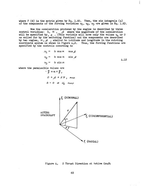
Now the acceleration produced by the engine is described by three<br />
control variables: b, LL , ,& where the magnitude of the acceleration<br />
will be specified by, 6 . (This variable will have only the values u. or 0<br />
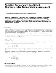
as called for by the switching function) <strong>and</strong> the components are described<br />
by two angles, Q!,,& , similar to latitude <strong>and</strong> longitude in the rotating<br />
coordinate system as shown in Figure &,2. Thus, the forcing functions are<br />
specified by the controls according to<br />
.Ul = b cosa cos p<br />
u2 = b coso( sin /<br />
“3 =<br />
bsinoc<br />
where the permissible values are<br />
6 = 0 C?? 0, ONLY<br />
ACTIVE<br />
SPACECRAFT<br />
Figure 4, 2 Thrust Direction at Active Craft<br />
62<br />
4.12