LTC4007 TYPICAL APPLICATIO U APPLICATIO S U DESCRIPTIO ...
LTC4007 TYPICAL APPLICATIO U APPLICATIO S U DESCRIPTIO ...
LTC4007 TYPICAL APPLICATIO U APPLICATIO S U DESCRIPTIO ...

Create successful ePaper yourself
Turn your PDF publications into a flip-book with our unique Google optimized e-Paper software.
<strong>LTC4007</strong><br />
<strong>TYPICAL</strong> PERFOR A CE CHARACTERISTICS<br />
PI FU CTIO S<br />
6<br />
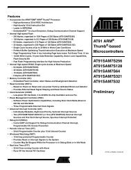
EFFICIENCY (%)<br />
100<br />
95<br />
90<br />
85<br />
80<br />
75<br />
U U U<br />
UW<br />
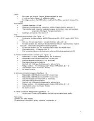
Efficiency at 19VDC VIN<br />
16.8V<br />
12.6V<br />
0.50 1.00 1.50 2.00 2.50 3.00<br />
CHARGE CURRENT (A)<br />
4007 G10<br />
DCIN (Pin 1): External DC Power Source Input. Bypass<br />
this pin with at least 0.01μF. See Applications Information.<br />
CHG (Pin 2): Charge Status Output. When the battery is<br />
being charged, the CHG pin is pulled low by an internal<br />
N-channel MOSFET. Internal 10μA pull-up to 3.5V. If<br />
VLOGIC is greater than 3.3V, add an external pull-up. The<br />
timer function can be defeated by forcing this pin below 1V<br />
(or connecting it to GND).<br />
ACP(Pin 3): Open-Drain output to indicate if the AC<br />
adapter voltage is adequate for charging. This pin is pulled<br />
low by an internal N-channel MOSFET if DCIN is below<br />
BAT. A pull-up resistor is required. The pin is capable of<br />
sinking at least 100μA.<br />
RT (Pin 4): Timer Resistor. The timer period is set by<br />
placing a resistor, RRT , to GND. This resistor is always<br />
required.<br />
The timer period is tTIMER = (1hour • RRT/154K). If this resistor is not present, the charger will not start.<br />
FAULT (Pin 5): Active low open-drain output that indicates<br />
charger operation has stopped due to a low-battery<br />
conditioning error, or that charger operation is suspended<br />
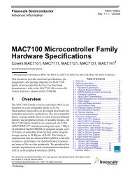
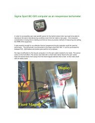
EFFICIENCY (%)<br />
100<br />
95<br />
90<br />
85<br />
80<br />
75<br />
Efficiency at 12.6V with 15VDC VIN<br />
0.50 1.00 1.50 2.00 2.50 3.00<br />
CHARGE CURRENT (A)<br />
4007 G11<br />
due to the thermistor exceeding allowed values. A pull-up<br />
resistor is required if this function is used. The pin is<br />
capable of sinking at least 100μA.<br />
GND (Pin 6): Ground for Low Power Circuitry.<br />
3C4C (Pin 7): Select 3-cell or 4-cell float voltage by<br />
connecting this pin to GND or open, respectively. Internal<br />
14μA pull-up to 5.3V. This pin can also be driven with<br />
open-collector/drain logic levels. High: 4 cell. Low: 3 cell.<br />
LOBAT (Pin 8): Low-Battery Indicator. Active low digital<br />
output. Internal 10μA pull-up to 3.5V. If the battery<br />
voltage is below 2.5V/cell (or 2.44V/cell for 4.1V chemistry<br />
batteries) LOBAT will be low. The pin is capable of<br />
sinking at least 100μA. If V LOGIC is greater than 3.3V, add<br />
an external pull-up.<br />
NTC (Pin 9): A thermistor network is connected from NTC<br />
to GND. This pin determines if the battery temperature is<br />
safe for charging. The charger and timer are suspended<br />
and the FAULT pin is driven low if the thermistor indicates<br />
a temperature that is unsafe for charging. The thermistor<br />
function may be disabled with a 300k to 500k resistor from<br />
DCIN to NTC.<br />
4007f