LTC4007 TYPICAL APPLICATIO U APPLICATIO S U DESCRIPTIO ...
LTC4007 TYPICAL APPLICATIO U APPLICATIO S U DESCRIPTIO ...
LTC4007 TYPICAL APPLICATIO U APPLICATIO S U DESCRIPTIO ...

You also want an ePaper? Increase the reach of your titles
YUMPU automatically turns print PDFs into web optimized ePapers that Google loves.
<strong>LTC4007</strong><br />
<strong>APPLICATIO</strong> S I FOR ATIO<br />
the full-scale voltage is reduced then, R4 = R5 = 2.49k and<br />
RPROG = 26.7k, the maximum charging current is still 2.5A<br />
but the FLAG trip point is maintained at 10% of full scale.<br />
There are other effects to consider. The voltage across the<br />
current comparator is scaled to obtain the same values as<br />
the 100mV sense voltage target, but the input referred<br />
sense voltage is reduced, causing some careful consideration<br />
of the ripple current. Input referred maximum comparator<br />
threshold is 117mV, which is the same ratio of 1.4x<br />
the DC target. Input referred IREV threshold is scaled back<br />
to –24mV. The current at which the switcher starts will be<br />
reduced as well so there is some risk of boost activity.<br />
These concerns can be addressed by using a slightly larger<br />
inductor to compensate for the reduction of tolerance to<br />
ripple current.<br />
Charger Voltage Programming<br />
Pins CHEM and C3C4 are used to program the charger final<br />
output voltage. The CHEM pin programs Li-Ion battery<br />
chemistry for 4.1V/cell (low) or 4.2V/cell (high). The C3C4<br />
pin selects either 3 series cells (low) or 4 series cells<br />
(high). It is recommended that these pins be shorted to<br />
ground (logic low) or left open (logic high) to effect the<br />
desired logic level. Use open-collector or open-drain outputs<br />
when interfacing to the CHEM and 3C4C pins from a<br />
logic control circuit.<br />
Table 3. Charger Voltage Programming<br />
VFINAL (V) 3C4C CHEM<br />
12.3 LOW LOW<br />
12.6 LOW HIGH<br />
16.4 HIGH LOW<br />
16.8 HIGH HIGH<br />
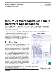
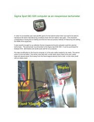
Setting the Timer Resistor<br />
The charger termination timer is designed for a range of<br />
1hour to 3 hour with a ±15% uncertainty. The timer is<br />
programmed by the resistor RRT using the following<br />
equation:<br />
tTIMER = 10 • 227 • RRT • 17.5pF (seconds)<br />
14<br />
U W U U<br />
t TIMER (MINUTES)<br />
200<br />
180<br />
160<br />
140<br />
120<br />
100<br />
80<br />
60<br />
40<br />
20<br />
0<br />
100<br />
150 200 250 300 350 400 450 500<br />
RRT (kΩ)<br />
Figure 7. t TIMER vs R RT<br />
4007 F07<br />
It is important to keep the parasitic capacitance on the R T<br />
pin to a minimum. The trace connecting R T to R RT should<br />
be as short as possible.<br />
Soft-Start<br />
The <strong>LTC4007</strong> is soft started by the 0.12μF capacitor on the<br />
ITH pin. On start-up, ITH pin voltage will rise quickly to<br />
0.5V, then ramp up at a rate set by the internal 40μA pullup<br />
current and the external capacitor. Battery charging<br />
current starts ramping up when ITH voltage reaches 0.8V<br />
and full current is achieved with ITH at 2V. With a 0.12μF<br />
capacitor, time to reach full charge current is about 2ms<br />
and it is assumed that input voltage to the charger will<br />
reach full value in less than 2ms. The capacitor can be<br />
increased up to 1μF if longer input start-up times are<br />
needed.<br />
Input and Output Capacitors<br />
The input capacitor (C2) is assumed to absorb all input<br />
switching ripple current in the converter, so it must have<br />
adequate ripple current rating. Worst-case RMS ripple<br />
current will be equal to one half of output charging current.<br />
Actual capacitance value is not critical. Solid tantalum low<br />
ESR capacitors have high ripple current rating in a relatively<br />
small surface mount package, but caution must be<br />
4007f