Negative Temperature Coefficient Thermistors for Temperature ...
Negative Temperature Coefficient Thermistors for Temperature ...
Negative Temperature Coefficient Thermistors for Temperature ...

You also want an ePaper? Increase the reach of your titles
YUMPU automatically turns print PDFs into web optimized ePapers that Google loves.
<strong>Thermistors</strong> 5<br />
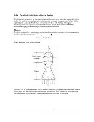
Intuitively, the best choice <strong>for</strong> R1 is the one that results in the (v) vs (T) graph that is closest to a 45° diagonal line over the<br />
temperature range of interest. This can be approximated analytically by using the equalslope concept mentioned be<strong>for</strong>e.<br />
From (11) the slope of the graph is found to be<br />
v<br />
<br />
T <br />
1<br />
Β <br />
s Β T<br />
1<br />
<br />
T0 <br />
<br />
<br />
1<br />
T<br />
Β <br />
s T T<br />
<br />
<br />
1<br />
<br />
T0 <br />
2<br />
<br />
<br />
Setting the slopes equal at the temperature extremes (TH ) and (TL ) produces a <strong>for</strong>mula <strong>for</strong> the ‘optimal’ (s)<br />
Β<br />
<br />
<br />
2 T<br />
<br />
H T<br />
s T H 2 T <br />
L TL 0 <br />
Β<br />
Β<br />
<br />
2 T<br />
<br />
H TH <br />
Β<br />
Β<br />
2 T L T L<br />
For the example at hand, equation (13) suggests setting R1 = 7417 Ohms. The value actually chosen <strong>for</strong> R1 in Fig.1 was 10k<br />
Ohms. 10k is simply a more convenient value. Also, eyeballing Fig.2, it looks like 10k might be a better choice, even if it isn’t,<br />
it’s close enough.<br />
So far in this example, we have relied exclusively on the simplified model. It would be nice to know the magnitude of the errors<br />
being introduced by using the simple model. To investigate that we need to compare the simplified model to the real thermistor<br />
behavior. For theoretical purposes this can be done by comparing the simplified model to the full cubic approximation because<br />
we know from experience that the cubic model is very accurate.<br />
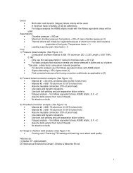
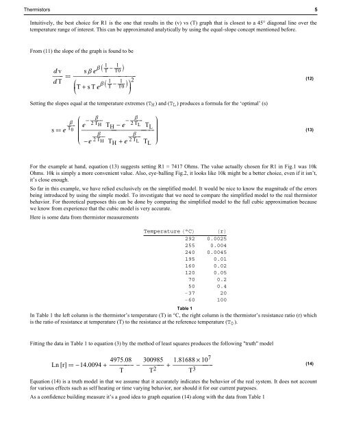
Here is some data from thermistor measurements<br />
<strong>Temperature</strong> °C r<br />
292 0.0025<br />
255 0.004<br />
240 0.0045<br />
195 0.01<br />
160 0.02<br />
120 0.05<br />
70 0.2<br />
50 0.4<br />
37 20<br />
60 100<br />
Table 1<br />
In Table 1 the left column is the thermistor’s temperature (T) in °C, the right column is the thermistor’s resistance ratio (r) which<br />
is the ratio of resistance at temperature (T) to the resistance at the reference temperature (T0 ).<br />
Fitting the data in Table 1 to equation (3) by the method of least squares produces the following "truth" model<br />
Ln r 14.0094 4975.08<br />
<br />
T<br />
300985<br />
<br />
T2 1.81688 107<br />
<br />
T3 Equation (14) is a truth model in that we assume that it accurately indicates the behavior of the real system. It does not account<br />
<strong>for</strong> various effects such as self heating or time varying behavior, nor should it <strong>for</strong> our current purposes.<br />
As a confidence building measure it’s a good idea to graph equation (14) along with the data from Table 1<br />
(12)<br />
(13)<br />
(14)