Negative Temperature Coefficient Thermistors for Temperature ...
Negative Temperature Coefficient Thermistors for Temperature ...
Negative Temperature Coefficient Thermistors for Temperature ...

You also want an ePaper? Increase the reach of your titles
YUMPU automatically turns print PDFs into web optimized ePapers that Google loves.
<strong>Thermistors</strong> 3<br />
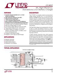
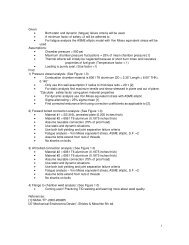
Here is the electrical circuit diagram <strong>for</strong> the sensor<br />
1<br />
C1<br />
10k 25C<br />
b<br />
RT1<br />
Off Board<br />
T<br />
10.0k<br />
R1<br />
0.1<br />
C2<br />
ADC<br />
Figure 1<br />
The thermistor (RT1) is connected to the positive supply. The positions of RT1 and R1 could have as easily been reversed and<br />
RT1 connected to the negative supply, but the positive connection has the advantage of producing an output voltage that<br />
increases with temperature. Also, if the Analog to Digital Converter (ADC) has a fairly consistent input impedance, its effect on<br />
R1 can be included as a simple parallel sum.<br />
The parameters given <strong>for</strong> RT1 (Β = 3750 and R0 = 10k Ohms) are the manufacture’s typical values. There are usually several<br />
tolerance grades available with ±10% being the least expensive. 5% tolerance units are very common, while 1% or better units<br />
begin to cost a lot more. The repeatability of a given unit is usually very good. Even a unit with a 10% manufacturing tolerance<br />
can be calibrated to measure with an accuracy better than 0.1°C over a wide temperature range. The long term stability of a<br />
thermistor sensor is usually determined by the packaging. Hermetic glass bead packages have good long term stability, as do<br />
some glasscoated surface mount units.<br />
Referring to Fig.1, capacitor C2 is a radio frequency interference filter. C2 may not be required <strong>for</strong> many applications. Capacitor<br />
C1 acts as a low pass filter, it not only reduces high frequency noise, it also reduces errors due to ADC charge injection. For<br />
many applications C1 could be reduced or eliminated. The thermistor’s own thermal time constant is often several seconds,<br />
which tends to be the limiting factor on signal bandwidth.<br />
Selecting the value of R1 is an interesting problem. Different values <strong>for</strong> R1 produce different curvatures in the circuit’s temperature<br />
to voltage relationship. For temperature controllers operating at a fixed temperature, R1 is usually selected to give the<br />
greatest sensitivity at the operating temperature. For measuring instruments, like this one, a common choice is to pick R1 so that<br />
the sensitivity is equal at the extremes of the measurement range. This constraint is easy to express analytically, and it tends to<br />
reduce the nonlinearity of the voltage vs temperature relationship over the range of interest.