The Atmel ATmega168A Microcontroller
The Atmel ATmega168A Microcontroller
The Atmel ATmega168A Microcontroller

You also want an ePaper? Increase the reach of your titles
YUMPU automatically turns print PDFs into web optimized ePapers that Google loves.
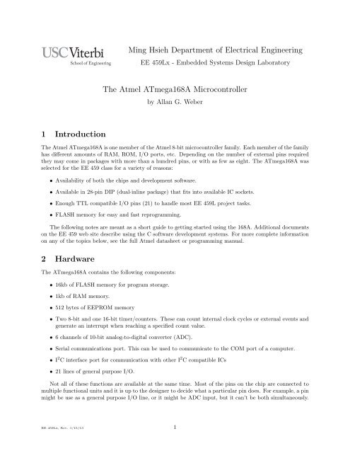
1 Introduction<br />
Ming Hsieh Department of Electrical Engineering<br />
EE 459Lx - Embedded Systems Design Laboratory<br />
<strong>The</strong> <strong>Atmel</strong> <strong>ATmega168A</strong> <strong>Microcontroller</strong><br />
by Allan G. Weber<br />
<strong>The</strong> <strong>Atmel</strong> <strong>ATmega168A</strong> is one member of the <strong>Atmel</strong> 8-bit microcontroller family. Each member of the family<br />
has different amounts of RAM, ROM, I/O ports, etc. Depending on the number of external pins required<br />
they may come in packages with more than a hundred pins, or with as few as eight. <strong>The</strong> <strong>ATmega168A</strong> was<br />
selected for the EE 459 class for a variety of reasons:<br />
• Availability of both the chips and development software.<br />
• Available in 28-pin DIP (dual-inline package) that fits into available IC sockets.<br />
• Enough TTL compatible I/O pins (21) to handle most EE 459L project tasks.<br />
• FLASH memory for easy and fast reprogramming.<br />
<strong>The</strong> following notes are meant as a short guide to getting started using the 168A. Additional documents<br />
on the EE 459 web site describe using the C software development systems. For more complete information<br />
on any of the topics below, see the full <strong>Atmel</strong> datasheet or programming manual.<br />
2 Hardware<br />
<strong>The</strong> <strong>ATmega168A</strong> contains the following components:<br />
• 16kb of FLASH memory for program storage.<br />
• 1kb of RAM memory.<br />
• 512 bytes of EEPROM memory<br />
• Two 8-bit and one 16-bit timer/counters. <strong>The</strong>se can count internal clock cycles or external events and<br />
generate an interrupt when reaching a specified count value.<br />
• 6 channels of 10-bit analog-to-digital converter (ADC).<br />
• Serial communications port. This can be used to communicate to the COM port of a computer.<br />
• I 2 C interface port for communication with other I 2 C compatible ICs<br />
• 21 lines of general purpose I/O.<br />
Not all of these functions are available at the same time. Most of the pins on the chip are connected to<br />
multiple functional units and it is up to the designer to decide what a particular pin does. For example, a pin<br />
might be use as a general purpose I/O line, or it might be ADC input, but it can’t be both simultaneously.<br />
EE 459Lx, Rev. 1/15/13 1
2.1 Minimum Connections<br />
In order to make the microcontroller operate the following connections must be made.<br />
2.1.1 Power and Ground<br />
<strong>The</strong> power supply voltage (5 volts) must be connected to the VCC input on pin 7. <strong>The</strong> ground connections<br />
are on pins 8 and 22.<br />
2.1.2 Clock<br />
Some sort of clock signal must be provided in order for the microcontroller to operate. On the <strong>ATmega168A</strong><br />
the clock can come from one of three different sources. <strong>The</strong> selection of the clock source is done by programming<br />
fuse bits in the chip.<br />
A TTL-compatible clock signal can be generated externally by other logic and connected to the XTAL1<br />
input (pin 9.) This probably the easiest way to generate the clock for the EE 459 projects. <strong>The</strong> lab has a<br />
supply of DIP oscillators in some of the more common frequencies. <strong>The</strong>se output a TTL level square wave<br />
that can be fed directly into the microcontroller and to other chips.<br />
Alternatively, the processor can generate a clock if a crystal is connected to the XTAL1 and XTAL2<br />
inputs. This method uses a plain crystal, not the DIP crystal oscillators as described above.<br />
<strong>The</strong> third method uses an internal oscillator that runs at approximately 8MHz. This is probably the<br />
least accurate way to generate a clock. Do not use this method if your project requires a clock running close<br />
to a specified frequency. <strong>The</strong> advantage of using the internal clock is that you do not need to provide any<br />
external signal and other functions are now available on pin 9. For example it can now be used as Port B<br />
bit 6 (PB6) thus giving the microcontroller 22 I/O pins.<br />
In applications where the UART0 serial communications interface is being used, the choice of clock<br />
frequency determines the baud rates that can be used for transmitting and receiving serial data. <strong>The</strong><br />
accuracy of the frequency of the baud rate depends on the clock frequency used for the microcontroller. If<br />
a high degree of accuracy is required, an external oscillator of the correct frequency will be needed. See<br />
Sec. 2.4 for more information.<br />
2.1.3 Reset<br />
<strong>The</strong> reset input (RESET, pin 1) must be in the high state for the processor to operate normally. This pin<br />
has an internal pull-up and does not have to be externally pulled-up to VCC in order for the processor to<br />
operate normally.<br />
2.1.4 SPI Programming<br />
<strong>The</strong> Flash memory on the <strong>ATmega168A</strong> is programed using connections to the reset input and three other<br />
pins: PB3, PB4 and PB5. <strong>The</strong>se three I/O pins can be used for other purposes as long as the design allows<br />
the programming hardware to have sole access to these pins during the programming process. Make sure<br />
that none of these pins is used as in input from some source that will continue to drive a signal at the 168A<br />
while the reset line is in the low state.<br />
2.2 I/O Ports<br />
When used with an external clock, the <strong>ATmega168A</strong> has 21 pins that can be configured for general purpose<br />
I/O. Many of these can also be used for other purposes such as analog-to-digital conversion, timers, etc. All<br />
the I/O port bits are capable of sourcing or sinking current to drive higher-current devices like LEDs.<br />
For each port there are three registers that control the actions of the individual bits of the port:<br />
Data Direction Register (DDRx) - <strong>The</strong>se registers determine whether the pins for that port are serving as<br />
inputs or outputs. Initially, or upon a reset signal, the bits in the DDRs are all zero which makes the<br />
corresponding I/O port bits inputs. To use a I/O port bit as an output, the corresponding bit in the<br />
DDR must be set to a one.<br />
EE 459Lx, Rev. 1/15/13 2
Input,<br />
pull-up off<br />
Output = 0<br />
DDxn, PORTxn<br />
0, 0 0, 1<br />
1, 0<br />
1, 1<br />
Input,<br />
pull-up on<br />
Output = 1<br />
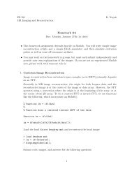
Figure 1: State of port bits when changing between input and output<br />
Data Register (PORTx) - When an I/O bit is configured as an output the corresponding bit in the PORTx<br />
register control the state of the output. If the bit is a one, the output line will go high. If the bit is a<br />
zero, the output line will go low. When an I/O bit is configured as in input, the bits in the PORTx<br />
register determine whether the internal pull-up resister is enabled. Writing a one to a bit in PORTx<br />
register turns on the corresponding pull-up resistor, and writing a zero turns it off.<br />
Port Input Pins (PINx) - <strong>The</strong> PINx registers are read-only registers that contain the value on the corresponding<br />
pin when the pin is configured to be an input. If the pin is high the value in the register is a<br />
one, and if the pin is low the value is a zero.<br />
A potential problem can sometimes occur in a design that requires switching bits in a port between input<br />
and output. Since the direction of the port bit and the output state of the port bit are controlled by bits<br />
in separate registers it’s not possible to switch both conditions at the same time. <strong>The</strong>y must be changed<br />
individually and this can lead to the port bit briefly being in an undesirable intermediate state.<br />
This situation is illustrated by the state diagram in Fig. 1. When changing a port bit from being an input<br />
with the pull-up resistors off to a high output, the port bit must briefly be either an input with pull-ups on,<br />
or a low output as shown by the solid lines between the states. Same would apply when make the reverse<br />
change. Similarly, when changing a port bit from being an input with pull-up on to a low output (or the<br />
reverse), the port bit must briefly be either an input with pull-up off, or a high output as shown by the<br />
dashed lines in the figure.<br />
2.2.1 Port B (PB)<br />
Port B on the <strong>ATmega168A</strong> has seven usable pins (PB0 through PB5 and PB7). A eighth bit, PB6, shares<br />
a pin with the XTAL1 input. If the chip is configured for an external clock, this pin is not available for I/O.<br />
Three of the pins (PB3, PB4 and PB5) are use for the SPI interface for programming the Flash memory.<br />
<strong>The</strong>se pins should not be used as inputs connected to sources that will continue to drive signals at the 168A<br />
while in the reset state.<br />
2.2.2 Port C (PC)<br />
Port C on the 168A has six pins (PC0 through PC5). A seventh bit, PC6, shares a pin with the RESET<br />
input. By changing the configuration fuse settings this bit can be use for I/O. Most of the pins in PC are<br />
shared with the analog-to-digital converter so if the ADC function is used one or more pins will not be<br />
available for general purpose I/O. In addition, PC4 and PC5 are use for the I 2 C interface and will not be<br />
available for general I/O if I 2 C is used.<br />
2.2.3 Port D (PD)<br />
Port D on the 168A has eight pins (PD0 through PD7). Two of the pins, PD0 and PD1, are shared with<br />
the serial communications interface and can not be used as I/O if the USART0 functions are used.<br />
EE 459Lx, Rev. 1/15/13 3
2.3 Timer/Counters<br />
<strong>The</strong> <strong>ATmega168A</strong> contains three timers:<br />
Timer/Counter0 - an 8-bit counter.<br />
Timer/Counter1 - a 16-bit counter.<br />
Timer/Counter2 - an 8-bit counter similar to Timer/Counter0 but with asynchronous clocking capability.<br />
<strong>The</strong> internal timers can be used to count events and generate an interrupt when a specified number of<br />
events has occurred. A common use of a timer is to implement a delay function by counting the number of<br />
internal clock cycles that occur. See the sample programs for examples of using the timers for this function.<br />
<strong>The</strong> example on the class web site uses the 16-bit timer but the the procedure is similar for the 8-bit<br />
timers. To implements a delay first set the timer for “Clear Timer on Compare Match” (CTC) mode using<br />
Output Compare Register A (OCR1A). <strong>The</strong> mode is set using four bits: WGM12 and WGM13 in TCCR1B,<br />
and WGM10 and WGM11 in TCCR1A. In most situations enabling the CTC interrupt is also required. This<br />
is done by setting the OCIE1A bit in the TIMSK1 register. In this mode the counter counts up to the value<br />
in OCR1A, generates an interrupt, clears the count and starts counting up again.<br />
Use the rate of the internal clock to calculate what count value the counter will need to count to. If<br />
the maximum value exceeds the range of the timer’s 16-bit register (greater then 65,535), determine what<br />
value to use in the prescaler to divide the internal clock by (8, 64, 256 or 1024) before it reaches the timer.<br />
<strong>The</strong> maximum count value, after any prescaling, is loaded into the Output Capture Register (OCR1A). <strong>The</strong><br />
prescaler is controlled by bits CS10, CS11 and CS12 in TCCR1B. <strong>The</strong> action of setting the prescaler bits to<br />
something other than all zeros starts the timer counting. To turn the timer off, set the prescaler bits to all<br />
zero.<br />
When the counter reaches the maximum count value, it generates an interrupt, resets the count value<br />
to zero and continues to count. <strong>The</strong> user program should service the interrupt and take whatever action<br />
is necessary. Keep in mind that the counter does not stop and wait for the interrupt to be serviced. It<br />
continues to count regardless of when or if the user program services the interrupt.<br />
2.4 Serial Communications Interface<br />
<strong>The</strong> <strong>ATmega168A</strong> contains a Universal Synchronous and Asynchronous serial Receiver and Transmitter<br />
(USART) that can be used to interface to the “COM” port on a PC or to another device. <strong>The</strong> data is<br />
transmitted from the <strong>ATmega168A</strong> on the TxD pin, and data is received on the RxD pin. If the external<br />
device is using RS-232 voltage levels for signaling, an external RS-232 transceiver chip like a Maxim MAX232<br />
is needed to translate between the voltage levels the <strong>ATmega168A</strong> uses and RS-232 positive and negative<br />
voltages.<br />
<strong>The</strong> USART0 transmitter (TxD) and receiver (RxD) use the same pins on the chip as I/O ports PD1<br />
and PD0. This means that applications that use the USART0 can not also use these two bits in Port D. It<br />
is not necessary to set any bits in the DDRD register in order to use the USART0<br />
<strong>The</strong> baud rates for sending and receiving serial data are derived from the main clock that drives the<br />
processor. <strong>The</strong> baud rate is determine by the value in the Baud Rate Register (UBBR) which is determined<br />
by the following equation.<br />
fosc<br />
UBRR =<br />
− 1<br />
16 × BAUD<br />
where fosc is the processor clock rate and BAUD is the desired baud rate.<br />
Since the baud rate is the result of dividing the clock by some integer value, in order to get an accurate<br />
baud rate it may be necessary to select an oscillator with a frequency that is not one of the normal sounding<br />
rates like 8MHz, 10MHz and 12MHz since these will not generate baud rates at exactly the correct frequency.<br />
For more detailed information on using the serial interface, see the document “Using the Serial Communications<br />
Interface” on the class web site.<br />
EE 459Lx, Rev. 1/15/13 4
2.5 I 2 C Interface<br />
<strong>The</strong> <strong>ATmega168A</strong> has the ability to communicate to other IC’s using the IIC or I 2 C serial interface. This is<br />
a two line bi-directional interface designed for medium speed communications between ICs on a board. One<br />
line is the clock, the other is for data. Numerous ICs are available on the market that have I 2 C interface<br />
such as EEPROMs, real-time-clocks, RAM, etc.<br />
On the 168A, the I 2 C interface is available on pins 27 and 28. <strong>The</strong>se pins are shared with both the ADC<br />
function and by Port C (PC4 and PC5). If the I 2 C interface is enabled then any other function on those<br />
pins is not available.<br />
If the pins mentioned above are not available for use, it is still possible to implement an I 2 C interface<br />
by using software to perform all the I 2 C transactions. Several I 2 C libraries are available from Internet sites,<br />
most of which will probably have to be modified to work with the 168A.<br />
For more information on using I 2 C, see the document “Using the IIC Interface” on the class web site.<br />
This document also contains information on using the oscilloscopes in the lab to debug I 2 C transactions.<br />
2.6 A/D Conversion<br />
<strong>The</strong> 168A has an internal 10-bit analog-to-digital converter for converting analog voltages to a binary value.<br />
<strong>The</strong> ADC inputs can be used for a variety of tasks such as sampling a voltage to determine the position of<br />
an input control. <strong>The</strong> ADC generates a value from 0 to 1023 for input levels between ground and whatever<br />
upper reference voltage is selected. For simple measurements, the upper reference voltage can be the ADC<br />
supply voltage input (AVCC) which is normally connected to the chips VCC supply voltage.<br />
<strong>The</strong> ADC can accept input from any one of 6 pins depending on the bits in control register. It can<br />
only do a conversion of one input at a time. <strong>The</strong> following example shows how to make the ADC sample a<br />
voltage between ground and AVCC on input ADC3 (pin 26). <strong>The</strong> conversion process requires an internal<br />
clock that can be generated from the microcontroller clock by configuring a prescalar to divide it down to<br />
reach a frequency between 50kHz and 200kHz.<br />
<strong>The</strong> following lines set the source of the reference voltage to AVCC, set the output to have the 8 most<br />
significant bits of the 10-bit result stored in the ADCH register, set the prescaler to divide the clock by 128,<br />
set the channel to be ADC3, and enable the ADC.<br />
ADMUX |= (1
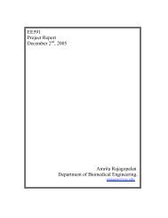
Figure 2: 6-pin ISP header mounted on a<br />
project board<br />
2.7 SPI Programming Interface<br />
PB5 (pin 19)<br />
Reset (pin 1) PB4 (pin 18)<br />
1<br />
6-pin ISP<br />
PB3 (pin 17)<br />
+5<br />
Connector<br />
Figure 3: Top view of connections to the<br />
6-pin ISP header<br />
In order to program the <strong>ATmega168A</strong> a project board needs to have a six-pin header on the board (Fig. 2)<br />
with connections to power, ground, reset and PB3, PB4 and PB5. Figure 3 shows the connections that need<br />
to be made. This is the view of the connector from the top of the board (component side). This six-pin<br />
header mates with the connector on the AVRISP mkII programming modules provided in the lab. When<br />
mounting the header on your board make sure to leave some room around it for the connector to mate with<br />
it. <strong>The</strong> cable to the connector comes in from the side where the power and ground pins are located so it’s<br />
best to leave extra space on this side of the connector for the cable.<br />
3 Software<br />
<strong>The</strong>re are several ways to create the code that gets programmed into the FLASH memory of the processor.<br />
<strong>The</strong> Mac Pro systems in the EE 459 lab have development software for programming in C and hardware for<br />
downloading the executable code to the microcontroller. <strong>The</strong> C development software runs in the MacOS X<br />
environment and is based on the “gcc” compiler package. It includes the compiler and linker, and software for<br />
downloading the program to the <strong>ATmega168A</strong>. <strong>The</strong> software is free and can be installed on any Intel-based<br />
Mac. Software for the 168A is discussed in a separate document available on the EE459 web site.<br />
EE 459Lx, Rev. 1/15/13 6