Installing and Testing a GFCI Receptacle - Leviton
Installing and Testing a GFCI Receptacle - Leviton
Installing and Testing a GFCI Receptacle - Leviton

Create successful ePaper yourself
Turn your PDF publications into a flip-book with our unique Google optimized e-Paper software.
<strong>Installing</strong> <strong>and</strong><br />
<strong>Testing</strong> a <strong>GFCI</strong><br />
<strong>Receptacle</strong><br />
Please read this leaflet<br />
completely before getting started.<br />
PK-93693-10-00-0A-X1<br />
3. Should you install it?<br />
F S<br />
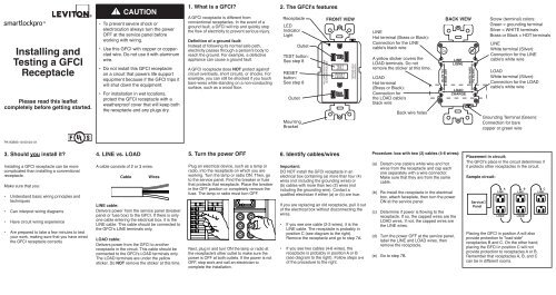
<strong>Installing</strong> a <strong>GFCI</strong> receptacle can be more<br />
complicated than installing a conventional<br />
receptacle.<br />
Make sure that you:<br />
• Underst<strong>and</strong> basic wiring principles <strong>and</strong><br />
techniques<br />
• Can interpret wiring diagrams<br />
• Have circuit wiring experience<br />
• Are prepared to take a few minutes to test<br />
your work, making sure that you have wired<br />
the <strong>GFCI</strong> receptacle correctly<br />
!<br />
CAUTION<br />
• To prevent severe shock or<br />
electrocution always turn the power<br />
OFF at the service panel before<br />
working with wiring.<br />
• Use this <strong>GFCI</strong> with copper or copperclad<br />
wire. Do not use it with aluminum<br />
wire.<br />
• Do not install this <strong>GFCI</strong> receptacle<br />
on a circuit that powers life support<br />
equipment because if the <strong>GFCI</strong> trips it<br />
will shut down the equipment.<br />
• For installation in wet locations,<br />
protect the <strong>GFCI</strong> receptacle with a<br />
weatherproof cover that will keep both<br />
the receptacle <strong>and</strong> any plugs dry.<br />
4. LINE vs. LOAD<br />
A cable consists of 2 or 3 wires.<br />
Cable Wires<br />
LINE cable:<br />
Delivers power from the service panel (breaker<br />
panel or fuse box) to the <strong>GFCI</strong>. If there is only<br />
one cable entering the electrical box, it is the<br />
LINE cable. This cable should be connected to<br />
the <strong>GFCI</strong>'s LINE terminals only.<br />
LOAD cable:<br />
Delivers power from the <strong>GFCI</strong> to another<br />
receptacle in the circuit. This cable should be<br />
connected to the <strong>GFCI</strong>'s LOAD terminals only.<br />
The LOAD terminals are under the yellow<br />
sticker. Do NOT remove the sticker at this time.<br />
1. What is a <strong>GFCI</strong>?<br />
A <strong>GFCI</strong> receptacle is different from<br />
conventional receptacles. In the event of a<br />
ground fault, a <strong>GFCI</strong> will trip <strong>and</strong> quickly stop<br />
the flow of electricity to prevent serious injury.<br />
Definition of a ground fault:<br />
Instead of following its normal safe path,<br />
electricity passes through a person's body to<br />
reach the ground. For example, a defective<br />
appliance can cause a ground fault.<br />
A <strong>GFCI</strong> receptacle does NOT protect against<br />
circuit overloads, short circuits, or shocks. For<br />
example, you can still be shocked if you touch<br />
bare wires while st<strong>and</strong>ing on a non-conducting<br />
surface, such as a wood floor.<br />
5. Turn the power OFF<br />
Plug an electrical device, such as a lamp or<br />
radio, into the receptacle on which you are<br />
working. Turn the lamp or radio ON. Then, go<br />
to the service panel. Find the breaker or fuse<br />
that protects that receptacle. Place the breaker<br />
in the OFF position or completely remove the<br />
fuse. The lamp or radio must turn OFF.<br />
Next, plug in <strong>and</strong> turn ON the lamp or radio at<br />
the receptacle's other outlet to make sure the<br />
power is OFF at both outlets. If the power is not<br />
OFF, stop work <strong>and</strong> call an electrician to<br />
complete the installation.<br />
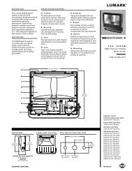
2. The <strong>GFCI</strong>'s features<br />
<strong>Receptacle</strong><br />
LED<br />
Indicator<br />
Light<br />
Outlet<br />
TEST button:<br />
See step 8<br />
RESET<br />
button:<br />
See step 8<br />
Outlet<br />
Mounting<br />
Bracket<br />
FRONT VIEW<br />
FOLLOW INSTRUCTIONS<br />
SUIVEZ INSTRUCTION<br />
6. Identify cables/wires<br />
RESET<br />
RESET<br />
Important:<br />
DO NOT install the <strong>GFCI</strong> receptacle in an<br />
electrical box containing (a) more than four (4)<br />
wires (not including the grounding wires) or<br />
(b) cables with more than two (2) wires (not<br />
including the grounding wire). Contact a<br />
qualified electrician if either (a) or (b) are true.<br />
If you are replacing an old receptacle, pull it out<br />
of the electrical box without disconnecting the<br />
wires.<br />
• If you see one cable (2-3 wires), it is the<br />
LINE cable. The receptacle is probably in<br />
position C (see diagram to the right).<br />
Remove the receptacle <strong>and</strong> go to step 7A.<br />
• If you see two cables (4-6 wires), the<br />
receptacle is probably in position A or B<br />
(see diagram to the right). Follow steps a-e<br />
of the procedure to the right.<br />
TESTTEST<br />
TEST MONTHLY<br />
TEST MENSUEL<br />
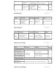
LINE<br />
Hot terminal (Brass or Black):<br />
Connection for the LINE<br />
cable's black wire<br />
A yellow sticker covers the<br />
LOAD terminals. Do not<br />
remove the sticker at this time.<br />
LOAD<br />
Hot terminal<br />
(Brass or Black):<br />
Connection for<br />
the LOAD cable's<br />
black wire<br />
Procedure: box with two (2) cables (4-6 wires):<br />
(a) Detach one cable's white wire <strong>and</strong> hot<br />
wires from the receptacle <strong>and</strong> cap each<br />
one separately with a wire connector.<br />
Make sure that they are from the same<br />
cable.<br />
(b) Re-install the receptacle in the electrical<br />
box, attach faceplate, then turn the power<br />
ON at the service panel.<br />
(c) Determine if power is flowing to the<br />
receptacle. If so, the capped wires are the<br />
LOAD wires. If not, the capped wires are<br />
the LINE wires.<br />
(d) Turn the power OFF at the service panel,<br />
label the LINE <strong>and</strong> LOAD wires, then<br />
remove the receptacle.<br />
(e) Go to step 7B.<br />
Back wire holes<br />
Cu<br />
HOT WIRE<br />
FIL ACTIF<br />
BACK VIEW<br />
LINE<br />
LIGNE<br />
LOAD<br />
CHARGE<br />
AL<br />
WHITE WIRE<br />
FIL BLANC<br />
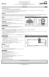
Placement in circuit:<br />
The <strong>GFCI</strong>'s place in the circuit determines if<br />
it protects other receptacles in the circuit.<br />
Sample circuit:<br />
Service<br />
Panel<br />
Screw (terminal) colors:<br />
Green = grounding terminal<br />
Silver = WHITE terminals<br />
Brass or Black = HOT terminals<br />
LINE<br />
White terminal (Silver):<br />
Connection for the LINE<br />
cable's white wire<br />
LOAD<br />
White terminal (Silver):<br />
Connection for the LOAD<br />
cable's white wire<br />
Grounding Terminal (Green):<br />
Connection for bare<br />
copper or green wire<br />
A B C<br />
LINE<br />
LINE LINE<br />
LOAD<br />
LOAD<br />
Placing the <strong>GFCI</strong> in position A will also<br />
provide protection to "load side"<br />
receptacles B <strong>and</strong> C. On the other h<strong>and</strong>,<br />
placing the <strong>GFCI</strong> in position C will not<br />
provide protection to receptacles A or B.<br />
Remember that receptacles A, B, <strong>and</strong> C<br />
can be in different rooms.
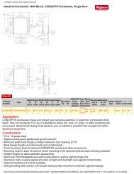
7. Connect the wires (choose A or B)... only after reading other side completely<br />
A: One Cable (2 or 3 wires) entering the box OR B: Two cables (4 or 6 wires) entering the box<br />
Grounding connection<br />
to box (if box has a<br />
grounding terminal)<br />
Wire Connector<br />
Electrical<br />
Box<br />
About Wire Connections:<br />
Side Wire:<br />
Wire<br />
LINE cable brings<br />
power to the <strong>GFCI</strong><br />
White<br />
Black<br />
Cu<br />
HOT WIRE<br />
FIL ACTIF<br />
LINE<br />
LIGNE<br />
LOAD<br />
CHARGE<br />
AL<br />
WHITE WIRE<br />
FIL BLANC<br />
Yellow<br />
sticker<br />
remains<br />
in place<br />
to cover<br />
the LOAD<br />
terminals<br />
Connect the LINE cable wires to the LINE terminals:<br />
• The white wire connects to the WHITE terminal (Silver)<br />
• The black wire connects to the HOT terminal (Brass or Black)<br />
Connect the grounding wire (only if there is a grounding wire):<br />
• For a box with no grounding terminal (diagram not shown): Connect the LINE cable's bare<br />
copper (or GREEN) wire directly to the grounding terminal on the <strong>GFCI</strong> receptacle.<br />
• For a box with a grounding terminal (diagram shown above): Connect a 6-inch bare copper<br />
(or GREEN) 12 or 14 AWG wire to the grounding terminal on the <strong>GFCI</strong>. Also connect a<br />
similar wire to the grounding terminal on the box. Connect the ends of these wires to the<br />
LINE cable's bare copper (or GREEN) wire using a wire connector. If these wires are<br />
already in place, check the connections.<br />
Complete the installation:<br />
• Fold the wires into the box, keeping the grounding wire away from the WHITE <strong>and</strong> HOT<br />
terminals. Screw the receptacle to the box <strong>and</strong> attach the faceplate.<br />
• Go to step 8.<br />
3/4" (1.9 cm)<br />
For Side wire -<br />
Loop clockwise 2/3 of the<br />
way around screw<br />
Back Wire:<br />
Wire<br />
3/4" (1.9 cm)<br />
For Back wire -<br />
Insert bare wire fully <strong>and</strong><br />
tighten terminal clamp on<br />
conductor ONLY<br />
Cu<br />
HOT WIRE<br />
FIL ACTIF<br />
LINE<br />
LIGNE<br />
LOAD<br />
CHARGE<br />
AL<br />
WHITE WIRE<br />
FIL BLANC<br />
Grounding connection<br />
to box (if box has a<br />
grounding terminal)<br />
Wire<br />
Connector<br />
Electrical<br />
Box<br />
For Side wire -<br />
Loop clockwise 2/3 of the<br />
way around screw<br />
LINE cable brings<br />
power to the <strong>GFCI</strong><br />
White<br />
Black<br />
Black<br />
White<br />
Cu<br />
HOT WIRE<br />
FIL ACTIF<br />
LINE<br />
LIGNE<br />
LOAD<br />
CHARGE<br />
AL<br />
WHITE WIRE<br />
FIL BLANC<br />
For Back wire -<br />
Insert bare wire fully <strong>and</strong><br />
tighten terminal clamp on<br />
conductor ONLY<br />
8. Test your work<br />
Why perform this test?<br />
• If you miswired the <strong>GFCI</strong> it may not prevent personal injury or death due<br />
to a ground fault (electrical shock).<br />
ORRESET<br />
LOAD cable feeds<br />
power to other<br />
receptacle(s)<br />
About Wire Connections:<br />
Side Wire:<br />
3/4" (1.9 cm)<br />
Wire<br />
Back Wire:<br />
Wire<br />
3/4" (1.9 cm)<br />
Connect the LINE cable wires to the LINE terminals:<br />
• The white wire connects to the WHITE terminal (Silver)<br />
• The black wire connects to the HOT terminal (Brass or Black)<br />
Connect the LOAD cable wires to the LOAD terminals:<br />
• Remove the YELLOW sticker to reveal the LOAD terminals<br />
• The white wire connects to the WHITE terminal (Silver)<br />
• The black wire connects to the HOT terminal (Brass or Black)<br />
Connect the grounding wires (only if there is a grounding wire):<br />
• Connect a 6-inch bare copper (or GREEN) 12 or 14 AWG wire to the grounding terminal on the<br />
<strong>GFCI</strong>. If the box has a grounding terminal, also connect a similar wire to the grounding terminal<br />
on the box. Connect the ends of these wires to the LINE or LOAD cable's bare copper (or<br />
GREEN) wire using a wire connector. If these wires are already in place, check the connections.<br />
Complete the installation:<br />
• Fold the wires into the box, keeping the grounding wire away from the WHITE <strong>and</strong> HOT<br />
terminals. Screw the receptacle to the box <strong>and</strong> attach the faceplate.<br />
• Go to step 8.<br />
Cu<br />
HOT WIRE<br />
FIL ACTIF<br />
LINE<br />
LIGNE<br />
LOAD<br />
CHARGE<br />
AL<br />
WHITE WIRE<br />
FIL BLANC<br />
• If you mistakenly connect the LINE wires to the LOAD terminals, the <strong>GFCI</strong><br />
will not reset <strong>and</strong> will not provide power to either the <strong>GFCI</strong><br />
receptacle face or any receptacles fed from the <strong>GFCI</strong>.<br />
Procedure:<br />
(a) This <strong>GFCI</strong> is shipped from the factory in the tripped condition <strong>and</strong> cannot<br />
be reset until it is wired correctly <strong>and</strong> power is supplied to the device.<br />
Plug a lamp or radio into the <strong>GFCI</strong> (<strong>and</strong> leave it plugged in). Turn the<br />
power ON at the service panel. Ensure that the <strong>GFCI</strong> is still in the tripped<br />
condition by pressing the TEST button. If the indicator light on the <strong>GFCI</strong><br />
receptacle face is ON <strong>and</strong> the lamp or radio is OFF go to the<br />
Troubleshooting section because LINE <strong>and</strong> LOAD wiring connections have<br />
been reversed. You will not be able to RESET the <strong>GFCI</strong> in this condition.<br />
(b) Press the RESET button fully. If the lamp or radio turns ON <strong>and</strong> the<br />
Indicator Light turns ON, the <strong>GFCI</strong> has been installed correctly. If the <strong>GFCI</strong><br />
cannot be reset, go to the Troubleshooting section.<br />
(c) If you installed your <strong>GFCI</strong> using step 7B press the TEST button, then plug<br />
a lamp or radio into surrounding receptacles to see which one(s), in<br />
addition to the <strong>GFCI</strong>, lost power when you pressed the TEST button. DO<br />
NOT plug life saving devices into any of the receptacles that lost power.<br />
Place a "<strong>GFCI</strong> PROTECTED OUTLET" sticker on every receptacle that<br />
lost power, then press the RESET button to reset the <strong>GFCI</strong>.<br />
(d) Press the TEST button (then RESET button) every month to assure proper operation. If the<br />
Indicator light does not go out <strong>and</strong> come back on or if the <strong>GFCI</strong> cannot be reset, then it must<br />
be replaced.<br />
NOTE:<br />
<strong>GFCI</strong>'s contain a lockout feature that will prevent RESET if:<br />
• There is no power being supplied to the <strong>GFCI</strong>.<br />
• The <strong>GFCI</strong> is miswired due to reversal of the LINE <strong>and</strong> LOAD leads.<br />
• The <strong>GFCI</strong> cannot pass its internal test, indicating that it may not be able to provide protection<br />
in the event of a ground fault.<br />
TROUBLESHOOTING<br />
Turn the power OFF <strong>and</strong> check the wire connections against the appropriate wiring diagram in step 7A<br />
or 7B. Make sure that there are no loose wires or loose connections. Start the test from the beginning of<br />
step 8 if you rewired any connections to the <strong>GFCI</strong>.<br />
Cat. No.<br />
X7599<br />
X7899<br />
General Information<br />
Ratings<br />
15A-125V AC, 60 Hz<br />
Tamper Resistant Shallow <strong>GFCI</strong> <strong>Receptacle</strong><br />
20A-125V AC, 60 Hz<br />
Tamper Resistant Shallow <strong>GFCI</strong> <strong>Receptacle</strong><br />
All devices rated 20A feed-through<br />
© 2010 <strong>Leviton</strong> Mfg. Co., Inc.<br />
For Technical Assistance Call: 1-800-824-3005 (U.S.A. Only)<br />
1 800 405-5320 (Canada Only)<br />
www.leviton.com<br />
TESTTEST<br />
RESET<br />
TESTTEST<br />
RESET<br />
RESET<br />
TESTTEST<br />
RESET<br />
RESET<br />
This product is covered by Patent Nos. US 6,040,967; US 6,246,558;<br />
US 6,282,070; US 6,381,112; US 6,437,953; US 6,646,838; US 6,657,834;<br />
US 6,864,766; US 6,944,001; US 7,336,458; US 7,400,479; US 7,463,124;<br />
CA 2,425,810; MX 234,458; HK 1,059,844; CN ZL01819728.0;<br />
CN ZL200510089460.7; US 6,900,972; US 7,082,021; US 6,788,173;<br />
MX 251,584, US 7,355,117.<br />
Smartlock Pro is a Trademark of <strong>Leviton</strong> Manufacturing Co., registered in<br />
the United States, Canada <strong>and</strong> Mexico<br />
LIMITED 2 YEAR WARRANTY AND EXCLUSIONS<br />
<strong>Leviton</strong> warrants to the original consumer purchaser <strong>and</strong> not for the benefit of anyone else that this product at the time of its sale by <strong>Leviton</strong><br />
is free of defects in materials <strong>and</strong> workmanship under normal <strong>and</strong> proper use for two years from the purchase date. <strong>Leviton</strong>’s only obligation<br />
is to correct such defects by repair or replacement, at its option, if within such two year period the product is returned prepaid, with proof of<br />
purchase date, <strong>and</strong> a description of the problem to <strong>Leviton</strong> Manufacturing Co., Inc., Att: Quality Assurance Department, 201 North<br />
Service Road, Melville, New York 11747. This warranty excludes <strong>and</strong> there is disclaimed liability for labor for removal of this product or<br />
reinstallation. This warranty is void if this product is installed improperly or in an improper environment, overloaded, misused, opened,<br />
abused, or altered in any manner, or is not used under normal operating conditions or not in accordance with any labels or instructions.<br />
There are no other or implied warranties of any kind, including merchantability <strong>and</strong> fitness for a particular purpose, but if any<br />
implied warranty is required by the applicable jurisdiction, the duration of any such implied warranty, including merchantability <strong>and</strong> fitness for<br />
a particular purpose, is limited to two years. <strong>Leviton</strong> is not liable for incidental, indirect, special, or consequential damages, including<br />
without limitation, damage to, or loss of use of, any equipment, lost sales or profits or delay or failure to perform this warranty<br />
obligation. The remedies provided herein are the exclusive remedies under this warranty, whether based on contract, tort or otherwise.<br />
PK-93693-10-00-0A-X1