BURNDY - Nedco
BURNDY - Nedco
BURNDY - Nedco

Create successful ePaper yourself
Turn your PDF publications into a flip-book with our unique Google optimized e-Paper software.
C-26<br />
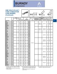
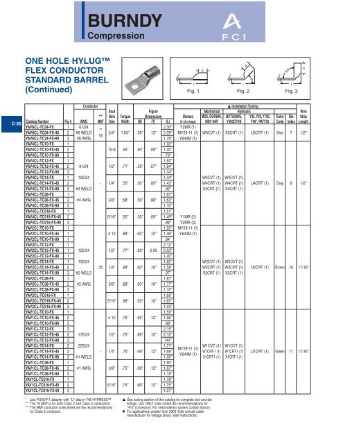
ONE HOLE HYLUG<br />
FLEX CONDUCTOR<br />
STANDARD BARREL<br />
(Continued)<br />
* Use PUADP-1 adapter with "U" dies in Y46 HYPRESS<br />
** The 16 MM 2 is for both Class 2 and Class 5 conductors.<br />
*** The MM 2 conductor sizes listed are the recommendations<br />
for Class 5 conductor.<br />
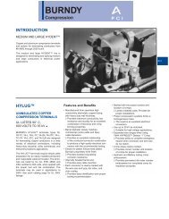
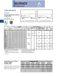
<strong>BURNDY</strong><br />
Compression<br />
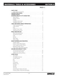
T<br />
L<br />
Fig. 1<br />
B<br />
B<br />
T T<br />
45°<br />
L<br />
90°<br />
Fig. 2 Fig. 3<br />
Conductor ▲ Installation Tooling<br />
Stud Figure Mechanical Hydraulic Wire<br />
*** Hole Tongue Dimensions Dieless MD6, OUR840, BCT500HS, Y35, Y39, Y750, Color Die Strip<br />
Catalog Number Fig # AWG MM2 Size Width (B) (T) (L) (# of crimps) MD7-34R Y500CTHS Y46*, PAT750 Code Index Length<br />
YAV6CL-TC34-FX<br />
YAV6CL-TC34-FX-45<br />
YAV6CL-TC34-FX-90<br />
1<br />
2<br />
3<br />
61/24<br />
#6 WELD<br />
#6 AWG<br />
**<br />
16<br />
3/4 1.05 .50 .13<br />
2.30<br />
2.39<br />
1.78<br />
Y2MR (1)<br />
MY29-11 (1)<br />
Y644M (1)<br />
W5CVT (1) X5CRT (1) U5CRT (1) Blue 7 1/2<br />
YAV4CL-TC10-FX 1 1.32<br />
YAV4CL-TC10-FX-45 2 10-8 .55 .50 .09 1.30<br />
YAV4CL-TC10-FX-90 3 .79<br />
YAV4CL-TC12-FX 1 1.92<br />
YAV4CL-TC12-FX-45 2 91/24 1/2 .71 .50 .07 1.84<br />
YAV4CL-TC12-FX-90 3 1.34<br />
YAV4CL-TC14-FX 1 105/24 1.44 W4CVT (1) W4CVT (1)<br />
YAV4CL-TC14-FX-45 2 - 1/4 .55 .50 .09 1.43 W4CRT (1) W4CRT (1) U4CRT (1) Gray 8 1/2<br />
YAV4CL-TC14-FX-90 3 #4 WELD .92 X4CRT (1) X4CRT (1)<br />
YAV4CL-TC38-FX 1 1.67<br />
YAV4CL-TC38-FX-45 2 #4 AWG 3/8 .58 .50 .08 1.63<br />
YAV4CL-TC38-FX-90 3 1.10<br />
YAV4CL-TC516-FX 1 1.51<br />
YAV4CL-TC516-FX-45 2 5/16 .55 .50 .09 1.49 Y1MR (2)<br />
YAV4CL-TC516-FX-90 3 .98 Y2MR (2)<br />
YAV2CL-TC10-FX 1 1.50 MY29-11 (1)<br />
YAV2CL-TC10-FX-45 1 # 10 .68 .63 .10 1.46 Y644M (1)<br />
YAV2CL-TC10-FX-90 1 .84<br />
YAV2CL-TC12-FX 1 2.12<br />
YAV2CL-TC12-FX-45 1 125/24 1/2 .77 .63 0.09 2.03<br />
YAV2CL-TC12-FX-90 1 1.40<br />
YAV2CL-TC14-FX 1 150/24 1.62 W2CVT (1) W2CVT (1)<br />
YAV2CL-TC14-FX-45 2 35 1/4 .68 .63 .10 1.58 W2CRT (1) W2CRT (1) U2CRT (1) Brown 10 11/16<br />
YAV2CL-TC14-FX-90 3 #2 WELD .97 X2CRT (1) X2CRT (1)<br />
YAV2CL-TC38-FX 1 1.81<br />
YAV2CL-TC38-FX-45 2 #2 AWG 3/8 .68 .63 .10 1.77<br />
YAV2CL-TC38-FX-90 3 1.15<br />
YAV2CL-TC516-FX 1 1.69<br />
YAV2CL-TC516-FX-45 2 5/16 .68 .63 .10 1.65<br />
YAV2CL-TC516-FX-90 3 1.03<br />
YAV1CL-TC10-FX 1 1.59<br />
YAV1CL-TC10-FX-45 2 # 10 .75 .69 .12 1.56<br />
YAV1CL-TC10-FX-90 3 .88<br />
YAV1CL-TC12-FX 3 2.15<br />
YAV1CL-TC12-FX-45 2 175/24 1/2 .75 .69 .12 2.12<br />
YAV1CL-TC12-FX-90 3 144<br />
YAV1CL-TC14-FX<br />
YAV1CL-TC14-FX-45<br />
2<br />
3<br />
225/24<br />
- 1/4 .75 .69 .12<br />
1.71<br />
1.69<br />
W1CVT (1) W1CVT (1)<br />
MY29-11 (1) YAV1CL-TC14-FX-90 3 #1 WELD 1.00<br />
Y644M (1)<br />
W1CRT-1 (1)<br />
X1CRT-1 (1)<br />
W1CRT-1 (1)<br />
X1CRT-1 (1)<br />
U1CRT (1) Green 11 11/16<br />
YAV1CL-TC38-FX 1 1.90<br />
YAV1CL-TC38-FX-45 2 #1 AWG 3/8 .75 .69 .12 1.87<br />
YAV1CL-TC38-FX-90 3 1.19<br />
YAV1CL-TC516-FX 1 1.78<br />
YAV1CL-TC516-FX-45 2 5/16 .75 .69 .12 1.75<br />
YAV1CL-TC516-FX-90 3 1.07<br />
▲ See tooling section of this catalog for complete tool and die<br />
listings. Use ONLY color-coded die recommendations for<br />
“-FX” connectors. For nest/indentor system contact factory.<br />
◆ For applications greater than 2000 Volts consult cable<br />
manufacturer for voltage stress relief instructions.<br />
L<br />
B
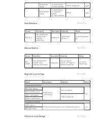
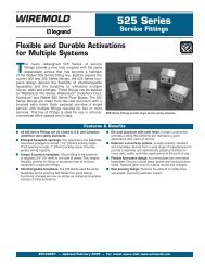
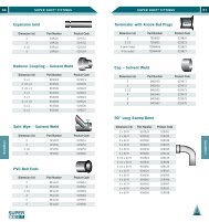
This chart provides a cross-reference between<br />
die index numbers marked on <strong>BURNDY</strong><br />
COMPRESSION CONNECTORS and the<br />
CORRESPONDING DIE SETS used with the<br />
various <strong>BURNDY</strong> INSTALLATION TOOLS.<br />
This is the only way to have a <strong>BURNDY</strong><br />
compression system.<br />
A die index number has been assigned to each<br />
required groove configuration. A prefix letter is<br />
used to indicate the specific installation tool for<br />
which the die has been designed, as shown<br />
below.<br />
<strong>BURNDY</strong><br />
Reference<br />
PRESENT INSTALLATION TOOL INDEX<br />
U 34 ART<br />
A - Y34A<br />
B - Y34BH<br />
C - Y48B<br />
12 - #12<br />
10 - #10<br />
8C - # 8<br />
6C - # 6<br />
5C - # 5<br />
4C - #4<br />
3C - #3<br />
2C - #2<br />
1C - #1<br />
25 - 1/0<br />
E - Y44B<br />
F - Y486RB<br />
G - Y34C<br />
L - Y60B<br />
Installation Tool<br />
Corresponding Die Set<br />
DIE IDENTIFICATION NUMBERING SYSTEM<br />
USE CHART (CHART III)<br />
WIRE SIZE (CHART II) OR INDEX<br />
TOOL TYPE (CHART I)<br />
CHART I<br />
P - Y46<br />
S - Y45<br />
U - Y35<br />
W - MD-6/OUR840<br />
CHART II<br />
26 - 2/0<br />
27 - 3/0<br />
28 - 4/0<br />
29 - 250 MCM<br />
30 - 300 MCM<br />
CHART III<br />
A - ALUMINUM<br />
B - INDENTOR NEST (USED WITH INDENTOR DIE # Y34P**)<br />
R - ROUND DIE (CIRCUMFERENTAL)<br />
T - TWIN DIE (BOTH HALVES)<br />
31 - 350 MCM<br />
32 - 400 MCM<br />
34 - 500 MCM<br />
36 - 600 MCM<br />
39 - 750 MCM<br />
44 - 1000 MCM<br />
X - OUR840/MD-6<br />
OR INDEX<br />
i.e., U312<br />
312 Die Index<br />
O-31