4.5 Air Standard Diesel Cycle: - nptel - Indian Institute of Technology ...
4.5 Air Standard Diesel Cycle: - nptel - Indian Institute of Technology ...
4.5 Air Standard Diesel Cycle: - nptel - Indian Institute of Technology ...

Create successful ePaper yourself
Turn your PDF publications into a flip-book with our unique Google optimized e-Paper software.
Gas Power <strong>Cycle</strong>s Pr<strong>of</strong>. U.S.P. Shet , Pr<strong>of</strong>. T. Sundararajan and Pr<strong>of</strong>. J.M . Mallikarjuna<br />
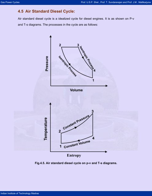
<strong>4.5</strong> <strong>Air</strong> <strong>Standard</strong> <strong>Diesel</strong> <strong>Cycle</strong>:<br />
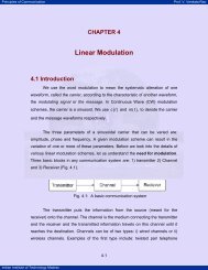
<strong>Air</strong> standard diesel cycle is a idealized cycle for diesel engines. It is as shown on P-v<br />
and T-s diagrams. The processes in the cycle are as follows:<br />
<strong>Indian</strong> <strong>Institute</strong> <strong>of</strong> <strong>Technology</strong> Madras<br />
2<br />
2<br />
1<br />
3<br />
Volume<br />
Entropy<br />
Fig.<strong>4.5</strong>. <strong>Air</strong> standard diesel cycle on p-v and T-s diagrams.<br />
1<br />
3<br />
4<br />
4
Gas Power <strong>Cycle</strong>s Pr<strong>of</strong>. U.S.P. Shet , Pr<strong>of</strong>. T. Sundararajan and Pr<strong>of</strong>. J.M . Mallikarjuna<br />
Process 1-2: Reversible adiabatic Compression.<br />
Process 2-3: Constant pressure heat addition.<br />
Process 3-5: Reversible adiabatic Compression.<br />
Process 4-1: Constant volume heat rejection.<br />
Consider ‘m’ kg <strong>of</strong> working fluid. Since the compression and expansion processes are<br />
reversible adiabatic processes, we can write,<br />
Now, we can write, thermal efficiency as,<br />
<strong>Indian</strong> <strong>Institute</strong> <strong>of</strong> <strong>Technology</strong> Madras<br />
( ) ( )<br />
Heat sup plied = m C T - T = h - h<br />
p 3 2 3 2<br />
( ) ( )<br />
Heat rejected = m C T - T = u - u<br />
v 4 1 4 1<br />
Workdone = m Cp ( T 3 - T 2) - m Cv( T 4 - T1)<br />
η =<br />
th<br />
( ) ( )<br />
m C ( T - T )<br />
m C T - T - m C T - T<br />
p 3 2 v 4 1<br />
p 3 2<br />
1 ⎛T - T ⎞<br />
= 1 - ⎜ ⎟<br />
4 1<br />
γ ⎝ T3 - T2<br />
⎠<br />
v v<br />
T 2 = T 1 r ; r = =<br />
v v<br />
2 2<br />
γ-1<br />
1 4<br />
2 2<br />
T3 v3<br />
= = r c = cut<strong>of</strong>f ratio<br />
T v<br />
T r T r T r γ<br />
= =<br />
3 c 2 c 1<br />
γ-1<br />
⎛ v3 ⎞ v4<br />
4 3⎜ ⎟ 3<br />
v4 v3<br />
⎛ ⎞<br />
T = T = T ⎜ ⎟<br />
⎝ ⎠ ⎝ ⎠<br />
-1<br />
γ-1
Gas Power <strong>Cycle</strong>s Pr<strong>of</strong>. U.S.P. Shet , Pr<strong>of</strong>. T. Sundararajan and Pr<strong>of</strong>. J.M . Mallikarjuna<br />
Hence,<br />
<strong>Indian</strong> <strong>Institute</strong> <strong>of</strong> <strong>Technology</strong> Madras<br />
1-γ<br />
⎛v4 v2<br />
⎞<br />
3<br />
⎝v2 v3<br />
⎠<br />
= T ⎜ . ⎟<br />
= r c T 1 r ⎜ ⎟<br />
r<br />
⎛ r ⎞<br />
= T3 ⎜ ⎟<br />
⎝rc⎠ 1-γ<br />
1-γ<br />
γ-1 ⎛ r ⎞<br />
γ<br />
; T 4 = r c T1<br />
⎝ c ⎠<br />
1 ⎧ γ<br />
⎪ r c T1- T ⎫<br />
1 ⎪<br />
η th = 1 - ⎨ γ-1 γ-1<br />
⎬<br />
γ<br />
⎩⎪r c r T 1 - r T1⎭⎪<br />
⎧ γ<br />
1-γ ⎪ rc-1 ⎫⎪<br />
= 1 - r ⎨ ⎬<br />
⎪⎩ γ ( rc-1) ⎭⎪<br />
From the above equation, it is observed that, the thermal efficiency <strong>of</strong> the diesel engine<br />
can be increased by increasing the compression ratio, r, by decreasing the cut-<strong>of</strong>f ratio,<br />
α2, or by using a gas with large value <strong>of</strong> γ. Since the quantity (r γ -1)/γ(rp-1) in above<br />
equation is always greater than unity, the efficiency <strong>of</strong> a <strong>Diesel</strong> cycle is always lower<br />
than that <strong>of</strong> an Otto cycle having the same compression ratio. However, practical <strong>Diesel</strong><br />
engines uses higher compression ratios compared to petrol engines.<br />
Mean effective Pressure:<br />
=<br />
Net workdone<br />
mep =<br />
Displacement volume<br />
( ) ( )<br />
m C T - T - m C T - T<br />
p 3 2 v 4 1<br />
v - v<br />
1 2<br />
⎛ v2 ⎞ ⎛ 1 ⎞<br />
v1 - v 2 = v1⎜1 - ⎟ = v1⎜1 - ⎟<br />
⎝ v1⎠ ⎝ r⎠<br />
⎛r - 1⎞<br />
⎝ r ⎠<br />
= m R T1<br />
⎜ ⎟<br />
( )<br />
m Cv γ -1 T1 ⎛r - 1⎞<br />
= ⎜ ⎟<br />
P ⎝ r ⎠<br />
1
Gas Power <strong>Cycle</strong>s Pr<strong>of</strong>. U.S.P. Shet , Pr<strong>of</strong>. T. Sundararajan and Pr<strong>of</strong>. J.M . Mallikarjuna<br />
<strong>Indian</strong> <strong>Institute</strong> <strong>of</strong> <strong>Technology</strong> Madras<br />
mep<br />
=<br />
( ) ( )<br />
m C T - T - m C T -T<br />
p 3 2 v 4 1<br />
⎛γ- 1⎞⎛r - 1⎞<br />
m C T ⎜ ⎟⎜ ⎟<br />
P ⎝ r ⎠<br />
v 1<br />
⎝ 1 ⎠<br />
⎛ P 1 r ⎞⎛ 1 ⎞⎧⎪⎛T<br />
3 - T2<br />
⎞ ⎛T 4 - T1<br />
⎞⎫⎪<br />
= ⎜ -<br />
r - 1<br />
⎟⎜ ⎟⎨γ⎜<br />
⎟ ⎜ ⎟⎬<br />
⎝ ⎠⎝γ- 1⎠⎪⎩ ⎝ T1 ⎠ ⎝ T1<br />
⎠⎭⎪<br />
( c ) ( c )<br />
⎧ γ-1 γ ⎫<br />
⎪<br />
γ r r - 1 - r - 1<br />
⎪<br />
= P 1 r⎨<br />
⎬<br />
⎪ ( r - 1 )( γ - 1)<br />
⎩ ⎭<br />
⎪<br />
Difference between Actual <strong>Diesel</strong> and the Otto Engines:<br />
Otto Engine<br />
1. Homogenous mixture <strong>of</strong> fuel and air<br />
formed in the carburetor is supplied<br />
to engine cylinder.<br />
2. Ignition is initiated by means <strong>of</strong> an<br />
electric spark plug.<br />
3. Power output is controlled by varying<br />
the mass <strong>of</strong> fuel-air mixture by<br />
means <strong>of</strong> a throttle valve in the<br />
carburetor.<br />
<strong>Diesel</strong> Engine<br />
1. No carburetor is used. <strong>Air</strong> alone is<br />
supplied to the engine cylinder. Fuel is<br />
injected directly into the engine<br />
cylinder at the end <strong>of</strong> compression<br />
stroke by means <strong>of</strong> a fuel injector.<br />
Fuel-air mixture is heterogeneous.<br />
2. No spark plug is used. Compression<br />
ratio is high and the high temperature<br />
<strong>of</strong> air ignites fuel.<br />
3. No throttle value is used. Power output<br />
is controlled only by means <strong>of</strong> the<br />
mass <strong>of</strong> fuel injected by the fuel<br />
injector.