Sub Module 2.12 Measurement of vacuum - nptel - Indian Institute of ...
Sub Module 2.12 Measurement of vacuum - nptel - Indian Institute of ...
Sub Module 2.12 Measurement of vacuum - nptel - Indian Institute of ...

Create successful ePaper yourself
Turn your PDF publications into a flip-book with our unique Google optimized e-Paper software.
Mechanical <strong>Measurement</strong>s Pr<strong>of</strong>. S.P.Venkateshan<br />
<strong>Indian</strong> <strong>Institute</strong> <strong>of</strong> Technology Madras<br />
<strong>Sub</strong> <strong>Module</strong> <strong>2.12</strong><br />
<strong>Measurement</strong> <strong>of</strong> <strong>vacuum</strong><br />
Pressure below the atmospheric pressure is referred to as <strong>vacuum</strong> pressure.<br />
The gage pressure is negative when we specify <strong>vacuum</strong> pressure. Absolute<br />
pressure, however, is certainly positive! It is possible to use, U tube<br />
manometers, Bourdon gages for the measurement <strong>of</strong> <strong>vacuum</strong> as long as it is<br />
not high <strong>vacuum</strong>. In the case <strong>of</strong> the U tube with mercury as the manometer<br />
liquid we can practically go all the way down to -760 mm mercury but there is<br />
no way <strong>of</strong> using it to measure <strong>vacuum</strong> pressures involving less than a fraction<br />
<strong>of</strong> a mm <strong>of</strong> mercury (also referred to as Torr – short for Torricelly). A U tube<br />
manometer can thus be used for rough measurement <strong>of</strong> <strong>vacuum</strong>. Figure 91<br />
(a) shows how it is done. A Bourdon gage capable <strong>of</strong> measuring <strong>vacuum</strong><br />
pressure will have the zero (zero gage pressure) somewhere in the middle <strong>of</strong><br />
the dial with the pointer going below zero while measuring <strong>vacuum</strong> and the<br />
pointer going above zero while measuring pressures above the atmosphere.<br />
A typical Bourdon gage capable <strong>of</strong> measuring <strong>vacuum</strong> is shown in Figure 91<br />
(b). Again a bourdon gage can not be used for measurement <strong>of</strong> high <strong>vacuum</strong>.<br />
Figure 91 (a) <strong>Measurement</strong> <strong>of</strong> <strong>vacuum</strong> by a U tube manometer<br />
(Visit http://hydraulicspneumatics.com/200/FPE/Pneumatics/Article/True/6460/Pneumatics)
Mechanical <strong>Measurement</strong>s Pr<strong>of</strong>. S.P.Venkateshan<br />
<strong>Indian</strong> <strong>Institute</strong> <strong>of</strong> Technology Madras<br />
(b) Bourdon gage to measure pressures above and below atmospheric<br />
pressure<br />
(Visit http://en.wikipedia.org/wiki/Image:WPGaugeFace.jpg)<br />
Now we discuss those instruments that are useful for measuring moderate<br />
and high <strong>vacuum</strong> ranging from, say 0.1 mm mercury to 10 -6 mm mercury.<br />
Such low pressures (absolute pressures) are used in many applications and<br />
hence there is a need to measure such pressures.<br />
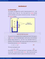
McLeod gage:<br />
Vacuum to<br />
be measured<br />
Capillary<br />
Bulb<br />
y<br />
Opening<br />
Reference level<br />
Movable<br />
Reservoir<br />
Manometer<br />
liquid<br />
Flexible<br />
hose<br />
Range: 10 -2 to 100 μm gage or 0.001 to 10 Pa<br />
Figure 92 Schematic <strong>of</strong> a McLeod gage<br />
McLeod gage is basically manometric method <strong>of</strong> measuring a <strong>vacuum</strong><br />
pressure that is useful between 0.01 and 100 μm <strong>of</strong> mercury column. This<br />
range translates to absolute pressure in the range <strong>of</strong> 0.001 to 10 Pa. Note<br />
that this range will also translate to 10 -8 to 10 -4 bar. The principle <strong>of</strong> operation<br />
<strong>of</strong> the McLeod gage is as described below (refer Figure 92).<br />
A known volume (V) <strong>of</strong> the gas at the <strong>vacuum</strong> pressure (p) given by the<br />
volume <strong>of</strong> the capillary, the bulb and the bottom tube up to the opening is<br />
trapped by lowering the movable reservoir down to the appropriate extent. It<br />
is then slowly raised till the level <strong>of</strong> the manometer liquid (usually mercury) in<br />
the movable reservoir is in line with the reference level marked on the stem <strong>of</strong><br />
the forked tube. This operation compresses the trapped gas to a pressure
Mechanical <strong>Measurement</strong>s Pr<strong>of</strong>. S.P.Venkateshan<br />
<strong>Indian</strong> <strong>Institute</strong> <strong>of</strong> Technology Madras<br />
(pc) equivalent to the head y indicated by the manometer as shown. The<br />
corresponding volume <strong>of</strong> the gas is given by the clear volume <strong>of</strong> the capillary<br />
Vc= ay where a is the area <strong>of</strong> cross section <strong>of</strong> the capillary. The gage is<br />
exposed to the ambient and hence remains at the ambient temperature during<br />
this operation.<br />
Since the entire process is isothermal Boyle’s law holds and hence we have<br />
pV = pV c c = pcay (97)<br />
Manometer equation gives<br />
pc − p= y<br />
(98)<br />
Note that all pressures are in mm <strong>of</strong> mercury in the above and y is also in mm.<br />
The area <strong>of</strong> cross section a is in mm 2 and the volume V is in mm 3 . We<br />
eliminate pc from Equations 97 and 98 to get<br />
ay ay<br />
p = ≈<br />
V ay V<br />
( − )<br />
2 2<br />
(99)<br />
The approximation is valid if the initial volume V is much greater than the final<br />
volume ay.
Mechanical <strong>Measurement</strong>s Pr<strong>of</strong>. S.P.Venkateshan<br />
<strong>Indian</strong> <strong>Institute</strong> <strong>of</strong> Technology Madras<br />
Example 33<br />
A McLeod gage has a volume <strong>of</strong> 100 ml and a capillary <strong>of</strong> 0.5 mm<br />
diameter. Estimate the pressure indicated by a reading <strong>of</strong> 25 mm <strong>of</strong><br />
mercury.<br />
What will be the error if the approximate formula is made use <strong>of</strong>?<br />
Volume <strong>of</strong> trapped gas V = 100 ml = 100× 10 = 10 mm<br />
3 5 3<br />
Capillary bore is d = 0.5 mm and hence the area <strong>of</strong> cross section <strong>of</strong> the<br />
capillary is<br />
The gage reading is y = 25 mm<br />
2 2<br />
πdπ× 0.5<br />
a = = = 0.196 mm<br />
4 4<br />
Using accurate formula given by first part <strong>of</strong> Equation 99, we have<br />
2 2<br />
ay 0.196× 25<br />
p= = = 0.00122724 Torr<br />
5<br />
( V − ay)<br />
( 10 − 0.196× 25)<br />
If we use the approximate formula (latter part <strong>of</strong> Equation 99), we get<br />
2 2<br />
ay 0.196× 25<br />
p ≈ = = 0.00122719 Torr<br />
5<br />
V 10<br />
Thus there is negligible error in the use <strong>of</strong> the approximate formula.<br />
The answer may be rounded to 1.227 milli-Torr.<br />
2
Mechanical <strong>Measurement</strong>s Pr<strong>of</strong>. S.P.Venkateshan<br />
Pirani gage:<br />
<strong>Indian</strong> <strong>Institute</strong> <strong>of</strong> Technology Madras<br />
Figure 93 Pirani gage with temperature compensation<br />
Another useful gage for measuring <strong>vacuum</strong> is the Pirani gage. The<br />
temperature <strong>of</strong> a heated resistance increases with a reduction <strong>of</strong> the<br />
background pressure. The rise in temperature changes its resistance just as<br />
we found in the case <strong>of</strong> RTD. As shown in Figure 93 the Pirani gage consists<br />
<strong>of</strong> two resistances connected in one arm <strong>of</strong> a bridge. One <strong>of</strong> the resistors is<br />
sealed in after evacuating its container while the other is exposed to the<br />
<strong>vacuum</strong> space whose pressure is to be measured. Ambient conditions will<br />
affect both the resistors alike and hence the gage will respond to only the<br />
changes in the <strong>vacuum</strong> pressure that is being measured. The Pirani gage is<br />
calibrated such that the imbalance current <strong>of</strong> the bridge is directly related to<br />
the <strong>vacuum</strong> pressure being measured. The range <strong>of</strong> this gage is from 1 μm<br />
mercury to 1 mm mercury that corresponds to 0.1 – 100 Pa absolute pressure<br />
range.<br />
R1<br />
R2<br />
R3<br />
I<br />
To<br />
Vacuum<br />
Range: 1 μm to 1 Torr gage or 0.1 to 100 Pa<br />
Evacuated<br />
and sealed
Mechanical <strong>Measurement</strong>s Pr<strong>of</strong>. S.P.Venkateshan<br />
Ionization gage:<br />
<strong>Indian</strong> <strong>Institute</strong> <strong>of</strong> Technology Madras<br />
Figure 94 Ionization gage circuitry<br />
Very high <strong>vacuum</strong> pressures (higher the <strong>vacuum</strong>, lower the absolute<br />
pressure) are measured using an ionization gage. Schematic <strong>of</strong> such a gage<br />
is shown in Figure 94. Physical construction <strong>of</strong> the ion gage is as shown in<br />
Figure 95.<br />
To<br />
Vacuum<br />
Grid<br />
Filament<br />
Plate<br />
Figure 95 Ion gage construction<br />
(Visit: thinksrs.com/downloads/ PDFs/ApplicationNotes/IG1BAGapp.pdf)<br />
The ion gage is similar to a triode valve which was used in radio receivers<br />
built with <strong>vacuum</strong> tubes, before the advent <strong>of</strong> transistors. The gage consists<br />
<strong>of</strong> a heated cathode that emits electrons. These electrons are accelerated<br />
Eg<br />
Ep<br />
ig ip<br />
Range: 1 to 10 -5 μm gage or 0.01 to 10 -6 Pa
Mechanical <strong>Measurement</strong>s Pr<strong>of</strong>. S.P.Venkateshan<br />
<strong>Indian</strong> <strong>Institute</strong> <strong>of</strong> Technology Madras<br />
towards the grid, basically wire mesh, which is maintained at a potential<br />
positive with respect to the cathode. The high speed electrons suffer<br />
collisions with the molecules <strong>of</strong> the residual gas in the bulb (that is exposed to<br />
the <strong>vacuum</strong> space) and ionizes these gas molecules. The electrons move<br />
towards the grid and manifest in the form <strong>of</strong> grid current ig. The positive ions<br />
move towards the plate that is maintained at a potential negative with respect<br />
to the grid. These ions are neutralized at the plate and consequently we have<br />
the plate current ip. The pressure in the bulb is then given by<br />
1 ip<br />
p =<br />
Sig<br />
(100)<br />
Here S is a proportionality called the ionization gage sensitivity. S has a<br />
typical value <strong>of</strong> 200 Torr -1 or or 2.67 kPa -1 . The gage cannot be used when<br />
the pressure is greater than about 10 -3 Torr since the filament is likely to burn<br />
<strong>of</strong>f. In practice the following is what is done:<br />
The <strong>vacuum</strong> space is provided with different pressure measuring devices<br />
such as:<br />
a) U tube mercury manometer for indicating that the initial evacuation is<br />
complete, usually achieved by a rotary pump or a reciprocating pump.<br />
b) A Pirani gage to measure the reduced pressure as the higher <strong>vacuum</strong><br />
is achieved by a diffusion pump or a turbo-molecular pump coupled<br />
with a cold trap.<br />
c) After the pressure has reduced to below 10 -6 Torr the ion gage is<br />
turned on measure the pressure in the high <strong>vacuum</strong> range.<br />
For more details the reader should look at books dealing with high <strong>vacuum</strong><br />
engineering.
Mechanical <strong>Measurement</strong>s Pr<strong>of</strong>. S.P.Venkateshan<br />
Alphatron gage:<br />
<strong>Indian</strong> <strong>Institute</strong> <strong>of</strong> Technology Madras<br />
To Vacuum<br />
Ion Collector<br />
Radioactive source<br />
Figure 96 Schematic <strong>of</strong> an Alphatron gage<br />
In the Alphatron gage ionization <strong>of</strong> the residual gas is brought about by alpha<br />
particles that are emitted by a radioactive material. The gage is similar to a<br />
common smoke detector in its operation. Since there is no hot cathode as in<br />
the case <strong>of</strong> ion gage considered earlier, the gage may be exposed to the<br />
atmospheric pressure without any fear <strong>of</strong> losing a filament! The rate <strong>of</strong> ion<br />
production is dependent on the residual pressure in the gage, and this<br />
pressure is the same <strong>of</strong> the <strong>vacuum</strong> pressure that is being measured. A<br />
collector electrode is maintained at a positive potential as shown in Figure 96.<br />
The ion current produces a potential drop Vo across the load resistor and this<br />
is indicative <strong>of</strong> the pressure. The output is fairly linear over the entire range<br />
from 1 milli Torr to the atmospheric pressure or 0.1 to 10 5 Pa.<br />
V<br />
R<br />
Vo<br />
Range: 0.001 to 1000 Torr gage or 0.1 to 10 5 Pa