SL-M810 - Canyon
SL-M810 - Canyon
SL-M810 - Canyon

Create successful ePaper yourself
Turn your PDF publications into a flip-book with our unique Google optimized e-Paper software.
ITEM<br />
NO.<br />
1<br />
2<br />
3<br />
4<br />
5<br />
6<br />
7<br />
8<br />
9<br />
1<br />
7<br />
5<br />
SHIMANO<br />
CODE NO.<br />
Y-6R1 98010<br />
Y-6R1 98020<br />
Y-6CD33000<br />
Y-6R1 02000<br />
Y-6R2 52000<br />
Y-6R1 98030<br />
Y-6R1 98040<br />
Y-6MP01200<br />
Y-6NX51200<br />
Y-6MP98080<br />
Y-8U9 14000<br />
Y-6R1 04000<br />
Y-6R2 54000<br />
Y-6R1 98050<br />
8<br />
9<br />
2<br />
DESCRIPTION<br />
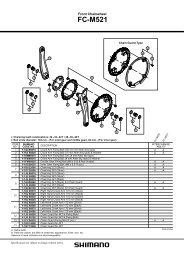
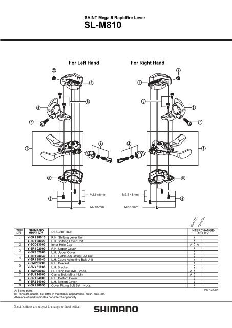
R.H. Shifting Lever Unit<br />
L.H. Shifting Lever Unit<br />
Inner Hole Cap<br />
R.H. Upper Cover<br />
L.H. Upper Cover<br />
R.H. Cable Adjustting Bolt Unit<br />
L.H. Cable Adjustting Bolt Unit<br />
R.H. Bracket<br />
L.H. Bracket<br />
<strong>SL</strong> Fixing Bolt (M4) 2pcs.<br />
Clamp Bolt (M6 x 14.8)<br />
R.H. Bottom Cover<br />
L.H. Bottom Cover<br />
Cover Fixing Bolt Set 4pcs.<br />
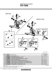
A: Same parts.<br />
B: Parts are usable, but differ in materirals, appearance, finish, size, etc.<br />
Absence of mark indicates non-interchangeability.<br />
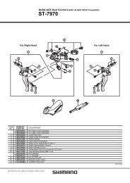
SAINT Mega-9 Rapidfire Lever<br />
<strong>SL</strong>-<strong>M810</strong><br />
For Left Hand For Right Hand<br />
6<br />
3<br />
4<br />
M2.6 8mm<br />
M2 5mm<br />
4<br />
M2.6 8mm<br />
M2 5mm<br />
3<br />
6<br />
2<br />
9<br />
8<br />
A<br />
A<br />
A<br />
5<br />
<strong>SL</strong>-M770<br />
7<br />
1<br />
<strong>SL</strong>-M530<br />
INTERCHANGE-<br />
ABILITY<br />
A<br />
0804-2829A
SI-6R20A-003-00<br />
General Safety Information<br />
WARNING<br />
• Downhill bicycle riding and freeriding are inherently dangerous<br />
activities. There is a risk of being involved in an accident that<br />
can result in a serious injury or even death. It is strongly recommended<br />
that riders wear protective head and body gear and<br />
perform thorough safety checks of their bicycles before riding.<br />
Please remember that you are riding at your own risk and that<br />
you have to consider your experience and your skills very carefully.<br />
• Obtain and read the service instructions carefully prior to installing<br />
the parts. Loose, worn or damaged parts may cause the bicycle to fall<br />
over and serious injury may occur as a result. We strongly recommend<br />
only using genuine Shimano replacement parts.<br />
• Read these Technical Service Instructions carefully, and keep them in a<br />
safe place for later reference.<br />
Note<br />
• If gear shifting operations do not feel smooth, wash the derailleur and<br />
lubricate all moving parts.<br />
• If the amount of looseness in the links is so great that adjustment is not<br />
possible, you should replace the derailleur.<br />
• If gear shifting adjustment cannot be carried out, check the degree of<br />
parallelism at the rear end of the bicycle. Also check if the cable is lubricated<br />
and if the outer casing is too long or too short.<br />
• Use a frame with internal cable routing is strongly discouraged as it has<br />
tendencies to impair the SIS shifting function due to its high cable resistance.<br />
• Use an outer casing which still has some length to spare even when the<br />
handlebars are turned all the way to both sides. Furthermore, check that<br />
the shifting lever does not touch the bicycle frame when the handlebars<br />
are turned all the way.<br />
• A special grease is used for the gear shifting cable. Do not use DURA-<br />
ACE grease or other types of grease, otherwise they may cause deterioration<br />
in gear shifting performance.<br />
• Grease the inner cable and the inside of the outer casing before use to<br />
ensure that they slide properly.<br />
• For smooth operation, use the specified outer casing and the bottom<br />
bracket cable guide.<br />
• Operation of the levers related to gear shifting should be made only<br />
when the front chainwheel is turning.<br />
• This shifting lever is compatible with triple front chainwheels.<br />
• This product is not warranted against damage resulting from use such<br />
as jumping while riding or if the bicycle falls over, except if such malfunctions<br />
result from non conforming materials or manufacturing methods.<br />
• Parts are not guaranteed against natural wear or deterioration resulting<br />
from normal use.<br />
• For maximum performance we highly recommend Shimano lubricants<br />
and maintenance products.<br />
• For any questions regarding methods of installation, adjustment, maintenance<br />
or operation, please contact a professional bicycle dealer.<br />
Technical Service Instructions SI-6R20A-003<br />
<strong>SL</strong>-<strong>M810</strong><br />
Shifting lever<br />
In order to realize the best performance, we recommend that the following<br />
combination be used.<br />
Series SAINT<br />
Shifting lever <strong>SL</strong>-<strong>M810</strong><br />
Outer casing OT-SP41 (SIS-SP41)<br />
Gears 9 / 18<br />
Front derailleur FD-M815 / FD-M817<br />
Front chainwheel FC-<strong>M810</strong>/ FC-M815<br />
Rear derailleur RD-<strong>M810</strong> / RD-<strong>M810</strong>-A<br />
Type SS /GS<br />
Freehub FH-<strong>M810</strong> / FH-M815<br />
Cassette sprocket CS-M770 / CS-HG80 / CS-6500<br />
Chain CN-HG93<br />
Bottom bracket guide SM-SP17 / SM-BT17<br />
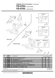
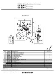
Gear shifting operation<br />
• This release lever is equipped with a 2-way release mechanism<br />
which allows release operations to be carried out by either pushing<br />
or pulling the lever.<br />
• Both lever (A) and lever (B) always return to the initial position<br />
when they are released after shifting. When operating one of the<br />
levers, always be sure to turn the crank arm at the same time.<br />
• This lever is designed for use with double and triple chainwheels.<br />
When used in combination with a double chainwheel, if you try to<br />
overstretch the shifting lever to the top position, it may break.<br />
< Rear ><br />
To shift from a small sprocket to a larger sprocket<br />
(Lever A)<br />
To shift one step only, press lever (A) to the (1) position. To shift two<br />
steps at one time, press to the (2) position.<br />
To shift from a large sprocket to a smaller sprocket<br />
(Lever B)<br />
Press lever (B) once to shift one step from a larger to a smaller<br />
sprocket.<br />
< Front ><br />
Lever (A) initial position<br />
Lever (B)<br />
2-way release<br />
To shift from the small chainring to the large chainring<br />
(Lever A)<br />
When lever (A) is pressed once, there is a shift of one step from the<br />
small chainring to the large chainring.<br />
To shift from the large chainring to the small chainring<br />
(Lever B)<br />
When lever (B) is pressed once, there is a shift of one step from the<br />
large chainring to the small chainring.<br />
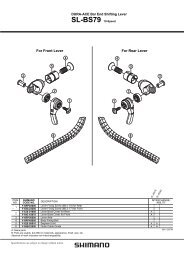
Installation of the lever<br />
Lever (B)<br />
2-way release<br />
Lever (A) initial position<br />
Use a handlebar grip with a maximum outer diameter of 36 mm.<br />
< Front ><br />
4 mm Allen key<br />
< Rear ><br />
Tightening torque :<br />
5 N·m {44 in. lbs.}<br />
This shifting lever can be installed either on the inside or the outside<br />
of the brake lever.<br />
If adjusting the position, be sure to secure it in the new position<br />
with the two fixing bolts.<br />
Tightening torque :<br />
2.5 N·m {22 in. lbs.}<br />
< Rear ><br />
< Front ><br />
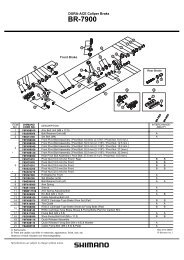
Installing the shifting cable<br />
< Rear ><br />
Connecting and securing the inner<br />
cable<br />
Operate the lever (B) 8 times or more to<br />
set the lever to the highest position. Then<br />
remove the inner hole cover and connect<br />
the inner cable.<br />
Move lever B in the direction of the arrow,<br />
and then install the inner hole cover by<br />
turning it as shown in the illustration until<br />
it stops. Do not turn it any further than<br />
this, otherwise it may damage the screw<br />
thread of the cover.<br />
Tightening torque :<br />
0.3 - 0.5 N·m {3 - 4 in. lbs.}<br />
Inner hole cover<br />
Be sure to read these service instructions in conjunction<br />
with the service instructions for the RD-<strong>M810</strong> / <strong>M810</strong>-A<br />
before use.<br />
< Front ><br />
Outboard Inboard<br />
3 mm Allen key<br />
Outboard Inboard<br />
• Install the shifting lever in a position where it will not obstruct brake<br />
operation and gear shifting operation.<br />
• Do not use in a combination which causes brake operation to be<br />
obstructed.<br />
• When installing the components to carbon frame/handle bar surfaces,<br />
verify with the manufacturer of the carbon frame/parts for<br />
their recommendation on tightening torque in order to prevent over<br />
tightening that can cause damage to the carbon material and/or<br />
under tightening that can cause lack of fixing strength for the components.<br />
Connect the cable to the rear<br />
derailleur and, after taking up<br />
the initial slack in the cable,<br />
re-secure to the rear derailleur<br />
as shown in the illustration.<br />
Pull<br />
3 mm Allen key<br />
Connecting and securing the inner<br />
cable<br />
Operate the lever (B) 2 times or more to<br />
set the lever to the lowest position. Then<br />
remove the inner hole cover and connect<br />
the inner cable.<br />
Lever (B)<br />
Inner cable<br />
Inner hole cover<br />
Inner cable<br />
Lever (B)<br />
Inner hole cover<br />
Note: Be sure that the cable is<br />
securely in the groove.<br />
Groove<br />
Tightening torque :<br />
5 - 7 N·m {44 - 60 in. lbs.}<br />
Move lever B in the direction of the arrow,<br />
and then install the inner hole cover by<br />
turning it as shown in the illustration until<br />
it stops. Do not turn it any further than<br />
this, otherwise it may damage the screw<br />
thread of the cover.<br />
• FD-M815<br />
< Normal type ><br />
• FD-M817<br />
< Normal type ><br />
After taking up the initial slack in the cable, re-secure to the front<br />
derailleur as shown in the illustration.<br />
Normal type<br />
Tightening torque :<br />
6 - 7 N·m {52 - 60 in. lbs.}<br />
Pull<br />
Note:<br />
Pass the cable<br />
through as shown<br />
in the illustration.<br />
Wire<br />
fixing bolt<br />
Note:<br />
Pass the cable<br />
through as shown<br />
in the illustration.<br />
Wire<br />
fixing bolt<br />
Top route type<br />
< Top route type ><br />
5 mm Allen key<br />
< Top route type ><br />
Be sure to read these service instructions in conjunction<br />
with the service instructions for the FD-M815 / M817<br />
before use.<br />
Cutting the outer casing (Rear / Front)<br />
When cutting the outer casing, cut the opposite end to the end<br />
with the marking. After cutting the outer casing, make the end<br />
round so that the inside of the hole has a<br />
uniform diameter.<br />
Attach the same outer end cap to the cut end of the outer casing.<br />
Outer end cap<br />
* If the rear derailleur moves to a large degree, such as in bicycles<br />
with rear suspension, it is recommended that you replace<br />
the cap with the accessory aluminum cap.<br />
The end of the outer casing which<br />
has the aluminum cap should be<br />
at the derailleur side.<br />
Aluminum cap<br />
Pull<br />
Derailleur side<br />
Inner hole cover<br />
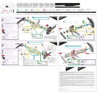
Replacing the covers for the <strong>SL</strong>-<strong>M810</strong><br />
Cover replacement and reassembly<br />
Disassembly and reassembly should only be carried out<br />
when the covers are being replaced.<br />
■ Removal<br />
1. Remove the inner hole cover, inner cable and adjustment<br />
bolt.<br />
2. Remove the three large screws and the small screw<br />
which are securing the cover.<br />
3. Turn the upper cover as shown in Figure 2 and then slide<br />
it in the direction of the arrow in Figure 3 to remove it.<br />
4. Push lever (A) back as far as it will go as shown in Figure<br />
4, and then turn the lower cover as shown in Figure 5 to<br />
remove it.<br />
(Figure 1)<br />
Small screw (x1) Large screws (x3)<br />
Tightening torque :<br />
0.05 N·m {0.4 in. lbs.}<br />
(Figure 2) (Figure 3)<br />
(Figure 4) (Figure 5)<br />
Lever (A)<br />
Upper cover<br />
■ Reassembly<br />
1. First install the lower cover and then the upper cover in<br />
the reverse procedure to removal. Assemble the upper<br />
and lower covers so the fit together with no gap between<br />
them.<br />
2. Tighten the three large screws and the small screw which<br />
secure the covers.<br />
3. Install the adjustment bolt, inner cable and inner hole<br />
cover in that order.<br />
One Holland, Irvine, California 92618, U.S.A. Phone: +1-949-951-5003<br />
Industrieweg 24, 8071 CT Nunspeet, The Netherlands Phone: +31-341-272222<br />
3-77 Oimatsu-cho, Sakai-ku, Sakai-shi, Osaka 590-8577, Japan<br />
Tightening torque :<br />
0.2 N·m {1 in. lbs.}<br />
Lower cover<br />
* Service Instructions in further languages are available at :<br />
http://techdocs.shimano.com<br />
Please note: specifications are subject to change for improvement without notice. (English)<br />
© Jun. 2010 by Shimano Inc. XBC SZK Printed in Japan.