xBoard Manual - Creative
xBoard Manual - Creative
xBoard Manual - Creative

You also want an ePaper? Increase the reach of your titles
YUMPU automatically turns print PDFs into web optimized ePapers that Google loves.
Xboard 1
Owner’s <strong>Manual</strong><br />
© 2006 E-MU Systems<br />
All Rights Reserved<br />
E-MU World Headquarters<br />
E-MU Systems<br />
1500 Green Hills Road<br />
Scotts Valley, CA 95066<br />
USA<br />
Asia Pacific Africa, Middle East<br />
<strong>Creative</strong> Technology Ltd<br />
31 International Business Park<br />
<strong>Creative</strong> Resource, Singapore 609921<br />
SINGAPORE<br />
Europe<br />
<strong>Creative</strong> Labs (Ireland) Ltd<br />
Ballycoolin Business Park<br />
Blanchardstown, Dublin 15<br />
IRELAND<br />
Japan<br />
<strong>Creative</strong> Media K. K.<br />
Kanda Eight Bldg., 3F<br />
4-6-7 Soto-Kanda<br />
Chiyoda-ku, Tokyo 101-0021<br />
JAPAN<br />
2 E-MU Systems
Table of Contents<br />
Introduction .................................................................7<br />
Requirements ...................................................................................................... 8<br />
On a PC: .................................................................................................................. 8<br />
On a Mac: ................................................................................................................ 8<br />
Hardware Installation ........................................................................................ 8<br />
Connecting the Xboard to your Computer ....................................................... 9<br />
USB Connection ..................................................................................................... 9<br />
MIDI Connection ................................................................................................... 9<br />
MIDI Interface ....................................................................................................... 10<br />
Software Installation ........................................................................................ 11<br />
Macintosh OS X .................................................................................................... 11<br />
Windows 2000 ...................................................................................................... 11<br />
Windows XP .......................................................................................................... 12<br />
Uninstalling all Audio Drivers and Applications .............................................. 12<br />
Note About Windows Logo Testing .................................................................... 12<br />
Troubleshooting ............................................................................................... 13<br />
Lost Communication ........................................................................................... 13<br />
Wrong Driver in Windows XP or Windows 2000 ............................................. 13<br />
Main Panel Controls ....................................................17<br />
Controller Knobs ........................................................20<br />
Normal mode ........................................................................................................ 20<br />
16 Channel Controller mode .............................................................................. 20<br />
3D MIDI and NRPN mode .................................................................................. 20<br />
Xboard 3
Xboard 61 Panel Controls ........................................... 21<br />
Using the Numeric Keypad ..................................................................................22<br />
Back Panel Description ............................................... 23<br />
Powering the Xboard ................................................. 24<br />
Inserting Batteries into the Xboard .....................................................................24<br />
Basic Operations ........................................................ 25<br />
Entering Data .................................................................................................... 25<br />
Selecting and Storing Patches .......................................................................... 25<br />
Changing the MIDI Channel ............................................................................ 26<br />
Transposing the Keyboard ............................................................................... 27<br />
Changing Controller CC Channel Numbers ................................................... 27<br />
16 Channel Control Mode ............................................................................... 27<br />
Working With Zones ........................................................................................ 28<br />
Note Latch Mode ............................................................................................... 29<br />
Latch Mode, Zones Disabled ...............................................................................29<br />
Latch Mode, Zones Enabled ................................................................................30<br />
Snap Shot .......................................................................................................... 30<br />
Bypass Mode ..................................................................................................... 31<br />
Editing Patch and Device Settings ................................................................... 31<br />
Scrolling Text Display ...........................................................................................32<br />
Edit Parameters ................................................................................................. 33<br />
PGM Send on Recall .............................................................................................33<br />
Send Program Change ..........................................................................................34<br />
Bank Sel MSB .........................................................................................................34<br />
Bank Sel LSB ..........................................................................................................35<br />
Program Change (PGM) Browse Mode ..............................................................35<br />
CC Send On Recall ...............................................................................................36<br />
Save CC Value in Patch ........................................................................................36<br />
Aftertouch On/Off ................................................................................................37<br />
Semitone Transpose ..............................................................................................37<br />
Velocity Curve Select ............................................................................................38<br />
16 Channel CC Number ......................................................................................38<br />
Latch High/Low Note ...........................................................................................38<br />
X1 and X2 Functions ............................................................................................39<br />
4 E-MU Systems
E-MU Xboard Control ..................................................44<br />
Definitions ........................................................................................................ 44<br />
Xboard Control Window .................................................................................. 45<br />
Bank View .............................................................................................................. 46<br />
Device .................................................................................................................... 47<br />
Basic Operation ................................................................................................ 47<br />
Patch Editor Tab ............................................................................................... 49<br />
MIDI Controller Knob Settings ........................................................................... 49<br />
Keyboard Settings ................................................................................................. 51<br />
Program Change per MIDI Channel ................................................................... 54<br />
Zones Tab .......................................................................................................... 55<br />
Zones Graphical Display ...................................................................................... 55<br />
Zones Settings ....................................................................................................... 56<br />
Menu Items ....................................................................................................... 60<br />
Preferences ............................................................................................................ 60<br />
Loading and Saving .............................................................................................. 61<br />
Edit Menu .............................................................................................................. 63<br />
View Menu ............................................................................................................. 63<br />
Device Menu ......................................................................................................... 63<br />
Help Menu ............................................................................................................. 63<br />
Appendix ...................................................................64<br />
MIDI Background ............................................................................................. 64<br />
MIDI Channels & Continuous Controllers ........................................................ 64<br />
MIDI Program Change Commands .................................................................... 65<br />
MIDI Bank Select Commands ............................................................................. 65<br />
Footpedal Wiring .............................................................................................. 65<br />
MIDI Implementation Chart ............................................................................ 66<br />
Index ..........................................................................71<br />
Xboard 5
6 E-MU Systems
Introduction<br />
INTRODUCTION<br />
Congratulations on your purchase of the E-MU Xboard 25, Xboard 49, or Xboard<br />
61 USB/MIDI controller. Xboard professional USB/MIDI controllers offer<br />
unmatched playability, real-time control and programmability in portable 25 key,<br />
49 key, and 61 key packages. All models feature full-size velocity-sensitive keys<br />
with aftertouch, pitch and modulation wheels, and 16 controller knobs. The<br />
Xboard 61 additionally features 16 Patch Select/Program Change buttons, and<br />
four Zone enable/disable buttons.<br />
These keyboards are ideal for either studio or stage use since they can be used as<br />
stand-alone MIDI controllers or with a USB equipped PC or Macintosh computer.<br />
The Xboard MIDI output can even be used as a MIDI interface for your computer<br />
when connected via USB. The Xboard is ultra-portable and can be powered via<br />
USB, battery, or using the optional 6 VDC power supply.<br />
Each of the 16 controller knobs can be programmed to any controller number on<br />
any MIDI channel. The keyboard can be transposed up or down ±4 octaves in<br />
order to play in any key and any pitch.<br />
You can also assign four different Keyboard Zones to four different MIDI<br />
channels, each using a different key range and velocity range. Also, each Zone can<br />
have different settings for Pitch Wheel, Mod Wheel, Latch, Aftertouch, Pedal, and<br />
Transpose.<br />
All Xboard models contain a host of extra features. The “Snap Shot” feature lets<br />
you send multiple controller values with a single button press. The “Xboard Latch<br />
Mode” lets you define a section of the keyboard as On/Off triggers—perfect for<br />
drum loops. Each of the 16 internal patches has a programmable footpedal/<br />
footswitch setting, can select one of eight velocity curves, and can send program<br />
changes for up to 16 MIDI channels.<br />
Xboard 7
Introduction<br />
Requirements<br />
The included Xboard Control software provides an intuitive desktop interface that<br />
makes it easy to create custom templates for all your favorite hardware and<br />
software instruments.<br />
On a PC:<br />
You must be running Windows 2000, XP, or XP x64 Edition, and your computer<br />
must support USB to communicate with the Xboard. The Xboard can operate in<br />
MIDI Output mode without a computer if power is supplied via a 6VDC adapter<br />
or batteries.<br />
On a Mac:<br />
You must be running Mac OS X 10.3.9 or later to connect the Xboard. The Xboard<br />
can operate in MIDI Output mode without a computer if power is supplied via a<br />
6VDC adapter or batteries.<br />
Hardware Installation<br />
The connection diagrams on the following pages show how to connect the Xboard<br />
to your computer or to another MIDI device.<br />
The supplied USB cable provides power and a two-way data link between the<br />
Xboard and your computer. The USB port on your computer is a small (1/8” x 3/<br />
8”) rectangular opening. The connector is keyed so you cannot plug it in wrong.<br />
The other end of the USB cable is square and plugs into the back of the Xboard.<br />
This end is also keyed to prevent incorrect insertion.<br />
Important: Windows 2000 users must install the software BEFORE the hardware is<br />
connected for the first time.<br />
If the Xboard is not connected to the computer via USB it requires a source of<br />
power in the form of a 6VDC adapter (tip positive) or (3) AA batteries.<br />
E-MU Systems 8
Introduction<br />
Connecting the Xboard to your Computer<br />
6 VDC<br />
Adapter<br />
(optional)<br />
USB Cable<br />
(included)<br />
MIDI Sound Module<br />
In<br />
CO1 A V1 27 P01 R A: P V I NTG<br />
3<br />
022 trn:Mel lotron tr S<br />
MIDI<br />
Cable<br />
(not included)<br />
Out<br />
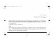
USB Connection<br />
USB provides a two-way data link<br />
between the Xboard and your<br />
computer and also supplies<br />
power to the Xboard. Always<br />
connect to the USB port on the<br />
computer itself—the USB port on<br />
your computer keyboard will not<br />
supply sufficient power.<br />
MIDI Connection<br />
The Xboard sends MIDI performance<br />
data to another MIDI<br />
device, such as a MIDI sound<br />
module. The Xboard always<br />
transmits MIDI data except<br />
when “Thru” mode is enabled.<br />
(See page 39.)<br />
Xboard 9
Introduction<br />
USB Cable<br />
(included)<br />
CO1 A V1 27 P01 R A: P V I NTG<br />
3<br />
022 trn:Mel lotron tr S<br />
E-MU Systems 10<br />
Out<br />
MIDI<br />
Cable<br />
MIDI Interface<br />
MIDI Sound Module<br />
The Xboard can function as a MIDI interface when connected to your computer via<br />
USB. Set the Xboard MIDI port to “Thru” (page 39) to transmit MIDI from your<br />
sequencing application to an external MIDI device.<br />
In
Introduction<br />
Software Installation<br />
Macintosh OS X<br />
Follow these instructions to install the Xboard Control software on a Macintosh<br />
computer.<br />
1. Insert the Xboard installation CD.<br />
2. Double-click the E-MU icon on your desktop.<br />
3. In the E-MU folder that opens, double-click the E-MU Xboard Apps & Docs<br />
installer.<br />
4. Follow the prompts to install the software.<br />
Windows 2000<br />
Follow these instructions to install the Xboard USB drivers and Xboard Control<br />
software on a Windows 2000 computer.<br />
1. Make sure the X-Board is NOT CONNECTED to your computer.<br />
2. Insert the E-MU software Installation CD into your CD-ROM drive. If<br />
Windows AutoPlay mode is enabled for your CD-ROM drive, the CD starts<br />
running automatically. If not, from your Windows desktop, click Start Run<br />
and type d:\setup.exe (replace d:\ with the drive letter of your CD-ROM<br />
drive). You can also simply open the CD and double-click Setup.exe.<br />
3. The installation splash screen appears. Follow the instructions on the screen<br />
to complete the installation. You will have the option to install E-MU Xboard,<br />
and the other software included on the CD.<br />
4. Choose “Continue Anyway” when you encounter the “Windows Logo<br />
Testing” warning screen. See the note on the following page.<br />
5. When prompted, restart your computer.<br />
6. Connect the Xboard to your computer using the supplied USB cable.<br />
Xboard 11
Introduction<br />
Windows XP<br />
Follow these instructions to install the Xboard USB drivers and Xboard Control<br />
software on a Windows XP computer.<br />
1. Connect the Xboard to your computer using the supplied USB cable, and turn it on.<br />
2. If Windows prompts you with an Add New Hardware Wizard, click Cancel.<br />
3. Insert the E-MU software Installation CD into your CD-ROM drive. If<br />
Windows AutoPlay is enabled for your CD-ROM drive, the CD starts running<br />
automatically. If not, click the Start menu, and select Run. Type<br />
d:\setup.exe (where d: is the drive letter of your CD-ROM drive) and<br />
click OK. You can also explore the CD and double-click Setup.exe.<br />
4. The installation splash screen appears. Follow the instructions on the screen<br />
to complete the installation. You will have the option to install E-Mu Xboard,<br />
and the other software included on the CD.<br />
5. Click Continue Anyway when you encounter the “Windows Logo Testing”<br />
warning screen. See “Note About Windows Logo Testing”.<br />
6. When prompted, restart your computer.<br />
Uninstalling all Audio Drivers and Applications<br />
At times you may need to uninstall or reinstall some or all of the Xboard's applications<br />
and device drivers to correct problems, change configurations, or upgrade<br />
outdated drivers or applications. Before you begin, close all Xboard-related<br />
applications. Applications running during the uninstallation will not be removed.<br />
1. Click Start Settings Control Panel.<br />
2. Double-click the Add/Remove Programs icon.<br />
3. Click the Install/Uninstall tab (or Change or Remove Programs button).<br />
4. Select the E-MU Xboard entry and then click the Change/Remove button.<br />
5. In the InstallShield Wizard dialog box, select the Remove ALL option.<br />
6. Click the Yes.<br />
7. Restart your computer when prompted.<br />
8. You may now re-install existing or updated E-MU device drivers or applications.<br />
Note About Windows Logo Testing<br />
When you install the Xboard USB drivers, you see a dialog box that informs you<br />
that the driver has not passed Windows Logo testing.<br />
However, the Xboard USB drivers have been rigorously tested using the same test<br />
procedures that a signed driver requires, and it passes in all important categories,<br />
including those that measure the relative stability of the driver. So, it is perfectly<br />
safe to install these drivers on your computer.<br />
E-MU Systems 12
Introduction<br />
Troubleshooting<br />
Lost Communication<br />
Should you lose MIDI communication between your Xboard and an audio application<br />
(Cubase, Sonar, etc.) or the Xboard Control software, the Xboard drivers<br />
may need to be re-selected in your application.<br />
1. Go to your application's MIDI I/O settings, de-select the Xboard for both<br />
MIDI input and output (or select a different MIDI device).<br />
2. Apply these changes and exit the dialog.<br />
3. Re-enter the application's MIDI settings and re-select the Xboard drivers. If<br />
this does not work, the application may need to be restarted.<br />
Wrong Driver in Windows XP or Windows 2000<br />
You may encounter a situation where the Xboard Control or Proteus X software is<br />
not running properly, even though the MIDI device itself seems to be working fine.<br />
If this is the case, you may be in a situation where the Microsoft USB Audio Device<br />
driver is running, rather than the E-MU USB Xboard Driver. This may happen if<br />
you add a USB Hub, or if you plug the Xboard keyboard into a different USB port<br />
than the one it was plugged into when you installed the Xboard software.<br />
To confirm the problem, do the following:<br />
1. Temporarily disconnect any USB audio devices you may have connected (USB<br />
audio/USB MIDI interfaces, etc.).<br />
2. Connect the Xboard to a USB port and switch the power to the on position.<br />
3. Windows may prompt the user with an Add New Hardware Wizard--Cancel<br />
this wizard.<br />
4. Start menu Settings Control Panel System Hardware Device<br />
Manager.<br />
5. Under Sound, Video and Game Controllers, find the device called either USB<br />
Audio Device or E-MU Xboardxx.<br />
6. Double-click on this device and then click on Driver.<br />
7. If the vendor shown here is E-MU Systems, you have run into a differentproblem,<br />
and you should contact Technical Support.<br />
If the vendor shown here is Microsoft, instead of E-MU Systems, you have<br />
indeed run into this situation. Continue on to the next section.<br />
Xboard 13
Introduction<br />
Windows XP You may recover by doing the following:<br />
1. Click on Update Driver.<br />
2. If you are running Windows Service Pack 2, following dialog box appears.<br />
Select No, not this time, and click Next.<br />
3. Select Install from a specific location (Advanced), and click Next.<br />
E-MU Systems 14
Introduction<br />
4. Select Don't Search, I will choose the driver to install, and click Next.<br />
5. Select E-MU USB-MIDI Device, and click Next.<br />
6. After a few moments, you will see the Microsoft Digital Signature warning.<br />
Click Continue Anyway.<br />
7. You should now be using the correct driver. It may be necessary to reboot<br />
your computer at this point.<br />
Xboard 15
Introduction<br />
Windows 2000 You may recover by doing the following:<br />
1. Double-click the incorrect listing in the Device Manager and choose Update<br />
Driver... from the Driver tab.<br />
2. Click Next, then Display a list of known drivers for this device...<br />
3. Click Next.<br />
4. Click Have Disk...<br />
5. Insert your Xboard install CD. If the disk autoruns, Exit the disk's installer.<br />
6. Click Browse.<br />
7. Browse to the following file, double-click the file, and click OK:<br />
X:\Audio\Drivers\Driver\emuumidi.inf (where X is your CD drive letter).<br />
8. Click Next.<br />
9. Click Next again. The Windows logo testing dialog should appear.<br />
10. Click Yes.<br />
11. Click Finish. It may be necessary to reboot your computer at this point.<br />
E-MU Systems 16
Main Panel Controls<br />
MAIN PANEL CONTROLS<br />
1<br />
2 3 12 14 9 10 11 13<br />
a b c<br />
4 5 6 7 8<br />
1. Data Entry / Master Volume Slider<br />
This control is used to enter data values when editing. When not being used<br />
for editing, the Data Slider functions as a master volume control transmitting<br />
a “Universal Real Time System Exclusive” message for Master Volume.<br />
2. Edit<br />
Press this button to edit the current patch and certain device settings.<br />
To Edit: Press the Edit button, choose the parameter to be edited using the<br />
keyboard keys, enter the value with the slider, then press Enter.<br />
3. MIDI Indicators<br />
The decimal points in the LED flash to indicate USB and MIDI activity.<br />
a. USB In<br />
b. USB Out<br />
c. MIDI Out<br />
The activity indicators can be enabled or disabled from the X1 menu.<br />
See “X1 and X2 Functions” on page 39.<br />
4. Home<br />
The Home button takes you out of edit mode and back into play mode<br />
without saving your edit. You can also think of this button as an Escape<br />
button which returns you to Play mode, the normal operating mode of the<br />
keyboard. The Home LED is lit whenever the Xboard is in Play mode.<br />
Xboard 17<br />
Panic
Main Panel Controls<br />
5. Store Patch<br />
This button stores your keyboard setup in one of the 16 memory locations.<br />
To Store a Patch: After pressing Store, select the desired patch number using<br />
the data slider, the Octave Transpose + and - buttons, or the Direct Patch<br />
Select buttons (Xboard 61 only), then press Enter to store the current setup.<br />
6. Enter<br />
Press Enter to confirm your settings when editing. In most cases, the Home<br />
LED illuminates after Enter is pressed, indicating a return to Play mode.<br />
7. Octave Down<br />
This button transposes the keyboard down one octave each time it is pressed.<br />
The new octave transpose value (-1, -2, -3, -4) momentarily appears in the<br />
display and the LED on the button remains lit unless transpose is set to zero.<br />
8. Octave Up<br />
This button transposes the keyboard up one octave each time it is pressed.<br />
The new octave transpose value (+1, +2, +3, +4) momentarily appears in the<br />
display and the LED on the button remains lit unless transpose is set to zero.<br />
MIDI Panic Button (7 + 8)<br />
Pressing both of the Octave Transpose buttons simultaneously causes the<br />
following MIDI messages to be sent on all 16 channels: “All Notes Off”, “All<br />
Sounds Off”, “Sustain Pedal Off”. This will turn off any “stuck notes” which<br />
occur when a synthesizer receives a note-on message without receiving a<br />
corresponding note-off message.<br />
Increment / Decrement Buttons<br />
The Octave Transpose buttons can be used as increment/decrement buttons<br />
whenever the Data Slider is active for modifying an edit value (either numeric<br />
or non-numeric settings). The increment/decrement buttons allow you to<br />
increase or decrease the value one unit at a time.<br />
9. Patch Select<br />
This button is used to select one of the 16 user patches in memory.<br />
To Select a Patch: Press the Patch Select button, then choose a patch using the<br />
data slider, the Octave Transpose + and - buttons, or the Direct Patch Select<br />
buttons (Xboard 61 only), and press Enter.<br />
E-MU Systems 18
Main Panel Controls<br />
10. MIDI Channel Select<br />
This button selects the Basic MIDI channel for the keyboard and all controls.<br />
To Select a MIDI Channel: Press the MIDI Channel button, then select the<br />
channel using the data slider, the Octave Transpose + and - buttons, or the<br />
Direct Patch Select buttons (Xboard 61 only), and press Enter.<br />
11. 16 Channel Control Mode<br />
In this mode, one MIDI Continuous Controller number is assigned to all 16<br />
knobs and each numbered knob transmits on the same-numbered MIDI<br />
channel. This gives you control of one parameter (such as volume or pan) for<br />
all 16 MIDI channels. See page 27 for detailed information.<br />
12. Latch Mode<br />
In this mode, pressed keys continue to play until they are pressed again to<br />
turn them off. This allows notes to be sustained for any length of time<br />
without having to hold down the keys. A range of latch keys can be defined<br />
using the “Latch High Note” and “Latch Low Note” edit parameters. See<br />
page 29.<br />
13. Knob Bypass<br />
Knob Bypass disables the transmission of MIDI messages from the knobs or<br />
control pedal/footswitch to avoid abrupt parameter jumps in performance.<br />
When Bypass is On, you can pre-set the knobs anywhere you like without<br />
sending MIDI controller messages. When you turn Bypass Off again, nothing<br />
is transmitted, but the knobs are now in the desired position for your performance.<br />
When you turn a knob, the value of the new knob position will be<br />
sent.<br />
This feature can also be used to set up any of the knobs the way you want,<br />
then send the values later using the Snapshot feature. See page 31.<br />
14. Snapshot<br />
When this button is pressed, the stored current settings of all performance<br />
controls (knobs, wheels, footswitch/pedal) are transmitted. This feature can<br />
also be used in conjunction with the Knob Bypass control to setup, and then<br />
send a group of MIDI continuous controllers messages at once.<br />
The Snapshot function is accessible only while in Play mode (i.e., whenever<br />
the Home LED is lit).<br />
Xboard 19
Controller Knobs<br />
CONTROLLER KNOBS<br />
The 16 Controller Knobs are designed to modify the sound during performance.<br />
MIDI Continuous Controller messages are transmitted whenever the knobs are<br />
turned (except when “Knob Bypass” is enabled).<br />
Whenever a controller knob is turned, the current value of the knob is displayed<br />
on the LED. Next, the letters “CC” flash on the display, followed by the MIDI<br />
Continuous Controller assigned to the knob, then the letters “CH”, and finally the<br />
MIDI channel on which the knob currently sends. To set the CC channel numbers<br />
of the knobs see page 27.<br />
Normal mode<br />
Any MIDI Continuous Controller number can be assigned to any knob. For<br />
instructions on setting this from the Xboard, see page 27. For help setting this<br />
using the Xboard Control Software, see page 49.<br />
16 Channel Controller mode<br />
In this mode, one MIDI Continuous Controller number is assigned to all 16 knobs<br />
and each numbered knob transmits on the same-numbered MIDI channel. This<br />
gives you control of one parameter (such as volume or pan) for all 16 MIDI<br />
channels. See page 27.<br />
3D MIDI and NRPN mode<br />
Using the Xboard Control software, any of the 16 Controller Knobs can be<br />
configured to run in 3D MIDI mode, or NRPN mode. For more information, see<br />
page 50.<br />
E-MU Systems 20
Xboard 61 Panel Controls<br />
XBOARD 61 PANEL CONTROLS<br />
1<br />
9<br />
Zones<br />
Enable<br />
2<br />
10<br />
3<br />
11<br />
4<br />
12<br />
1<br />
1 2 3 4<br />
■ Program<br />
Change Mode<br />
2 3 4<br />
1. Patch Select / Numeric Keypad<br />
These buttons serve a number of functions:<br />
• With Program Change mode turned off, you can select a patch from 1 to<br />
16 at any time. The LED for the current patch stays illuminated.<br />
• When changing MIDI channel, or Storing and Loading Patches with the<br />
main panel controls, use buttons 1 through 16 to make a selection.<br />
• For Program change mode, use buttons 1 through 10 to enter numerical<br />
values for Program Changes.<br />
• Use the numerical keypad buttons when entering numerical values, such<br />
as Edit functions.<br />
2. Zones Enable<br />
Enables or disables Zones functions in the active patch. When Zones are<br />
enabled, the LED illuminates.<br />
For the Xboard 25 or Xboard 49, you can enable or disable Zones using the<br />
X2 menu item “ZoE”(page 43) or the Xboard Control software (page 56).<br />
3. Keyboard Zones Buttons<br />
These buttons enable or disable individual Zones. When a Zone is enabled,<br />
the LED illuminates.<br />
For the Xboard 25 or Xboard 49, you can enable or disable individual Zones<br />
using the Xboard Control software (See page 58).<br />
Xboard 21<br />
5<br />
13<br />
6<br />
14<br />
7<br />
15<br />
8<br />
16
Xboard 61 Panel Controls<br />
4. Program Change Mode<br />
When you press this button, you switch between Program Change mode and<br />
Patch Select mode. The LED illuminates when in Program Change mode.<br />
• Program Change mode: allows you to send MIDI program changes to<br />
other equipment using the numerical buttons. (0-9)<br />
• Patch Select mode: allows you to select from 16 internal patches (1-16).<br />
The Program Change Mode button also doubles as the Enter button when it,<br />
along with the Enter button, flashes.<br />
Using the Numeric Keypad<br />
The numeric keypad allows you to enter numeric values for Program Changes, and<br />
other settings.<br />
Use 1-10 to Enter Numerical Values<br />
1<br />
9<br />
2<br />
10<br />
To use the numeric keypad to enter data, use the buttons labeled 1 through 10 to<br />
enter a value. The current value is reflected in the display. The “10” button acts as<br />
the value of 0, so if you want to enter a value of 109, you would press:<br />
1 + 10 + 9 +<br />
3<br />
11<br />
4<br />
12<br />
5<br />
13<br />
If you enter a value you don’t like, you can clear the value by entering “0” three<br />
times.<br />
E-MU Systems 22<br />
6<br />
14<br />
7<br />
15<br />
8<br />
16
Back Panel Description<br />
BACK PANEL DESCRIPTION<br />
1 2 3 4 5<br />
1. Footswitch / Footpedal Input<br />
This jack accepts either a footswitch or continuously variable footpedal. The<br />
default setting is for a footswitch. To use a footpedal, see page 40.<br />
Footswitch - Accepts either a normally-open or normally-closed momentary<br />
footswitch. The Xboard auto-senses the polarity on power-up.<br />
Footpedal - Accepts most standard footpedal types with a stereo plug. See the<br />
wiring diagram shown on page 65 for pedal wiring specifications.<br />
2. MIDI Output<br />
Outputs note and controller MIDI data from the Xboard. This jack can also be<br />
used as a MIDI interface from a computer software application. See page 39.<br />
Use a standard MIDI cable to connect the Xboard to the MIDI input jack of<br />
other MIDI devices.<br />
3. USB<br />
Connects Xboard to your computer via the supplied USB cable. The USB<br />
connection provides two-way communication when connected to the<br />
computer and also supplies power to the Xboard. Always connect to the USB<br />
jack on the computer itself and NOT to a low-power USB connection that<br />
may be present on your computer keyboard or other USB peripheral.<br />
4. 6 Volt DC Power<br />
This jack allows the Xboard to be powered from a standard 6VDC Adapter<br />
(positive tip) when not connected to the computer via USB.<br />
5. On/Off Switch<br />
This switch turns the Xboard on or off whether powered via USB, AC Adapter,<br />
or batteries.<br />
Xboard 23
Powering the Xboard<br />
POWERING THE XBOARD<br />
The Xboard can be powered using any of the following power sources:<br />
• USB from the host computer<br />
• 6 VDC Adapter (Optional - Part Number: 70EM779006000)<br />
• (3) AA batteries<br />
The priority of power sources is as follows:<br />
1. 6VDC power - will be used over all other power sources if available.<br />
2. USB power - will be used if connected and 6VDC is not available.<br />
3. Battery power - will be used only if no other power source is available.<br />
Inserting Batteries into the Xboard<br />
Sometimes it’s nice not to have to hassle with power at all. Thankfully the Xboard<br />
can be operated using (3) AA batteries. Battery life generally exceeds 5 hours using<br />
standard alkaline batteries. Lithium batteries typically last 16+ hours.<br />
To Insert Batteries:<br />
The battery compartment is located on the bottom of the unit.<br />
1. Press the two tabs toward the middle of the battery door while lifting up. The<br />
compartment door lifts up and out.<br />
2. Insert (3) AA batteries. Make sure you install them as indicated at the bottom<br />
of the battery compartment with + aligned with the + side of the battery.<br />
The battery compartment on the Xboard 25 and Xboard 49<br />
This Side<br />
Not Used<br />
Insert Batteries<br />
here<br />
3. Insert the tabs of the battery compartment door into the hinge slots, then<br />
press down to snap the door closed.<br />
E-MU Systems 24
Basic Operations<br />
BASIC OPERATIONS<br />
Entering Data<br />
There are several ways to enter data from the Xboard.<br />
• Data Slider - Move the slider to select the data value.<br />
• Octave Transpose buttons - Increment and decrement by pressing the “+”<br />
and “-” buttons.<br />
• Keyboard Data Entry - The black and white keyboard keys marked with<br />
numbers can be used to directly enter data values (except when changing the<br />
MIDI channel number or storing and selecting patches, since the keyboard remains<br />
“live” at these times).<br />
• Numeric Keypad (Xboard 61 only) - Type in the value using keys 1-10. See<br />
page 22.<br />
Selecting and Storing Patches<br />
The Xboard can hold 16 patches in its internal memory. A patch contains the<br />
settings for all user programmable controls of the Xboard.<br />
In addition, depending on the patch settings, the Xboard can send MIDI program<br />
changes message(s) and initial controller settings for the knobs, wheels and<br />
footswitch/pedal when a particular patch is selected.<br />
To Select a Patch Using the Main Panel:<br />
1. Press the Patch Select button, illuminating the LED. The Enter button and<br />
Program Change Mode button (Xboard 61) begin flashing.<br />
2. Select the desired patch number using the Data Slider or the Octave<br />
Transpose + and - buttons. On the Xboard 61, you can also use the Direct<br />
Patch Select buttons 1 through 16.<br />
On the Xboard 61, the new patch you selected begins flashing.<br />
3. Press Enter to confirm the operation. Press Home to cancel the operation.<br />
2<br />
1<br />
3<br />
Xboard 25<br />
Panic
Basic Operations<br />
To Select a Patch Using Direct Patch Select Buttons (Xboard 61):<br />
1. Make sure Program Change mode is off. The Program Change Mode button’s<br />
LED should not be lit.<br />
2. Press one of the Direct Patch Select buttons 1 through 16.<br />
To Store a Patch:<br />
1. Press the Store button. The Enter and Direct Patch Select (Xboard 61) LEDs<br />
begin flashing.<br />
2. Select the desired patch number using the Data Slider or the Octave<br />
Transpose + and - buttons. On the Xboard 61, you can also use the Direct<br />
Patch Select buttons 1 through 16.<br />
On the Xboard 61, the new patch you selected begins flashing.<br />
3. Press Enter to store the patch. Press Home to cancel the operation.<br />
2 1<br />
3<br />
Changing the MIDI Channel<br />
The MIDI specification allows for up to 16 channels to be used. This control allows<br />
you to set the Basic MIDI channel for data transmitted by the Xboard keyboard<br />
and controllers. Note that this setting is stored in and recalled from patches.<br />
To Change the MIDI Channel:<br />
1. Press the MIDI Channel button. The MIDI Channel LED illuminates. On the<br />
Xboard 61, the Direct Patch Select button representing the Current MIDI<br />
channel also illuminates.<br />
2. Select the desired MIDI channel using the Data Slider or the Octave<br />
Transpose + and - buttons. On the Xboard 61, you can also use the Direct<br />
Patch Select buttons 1 through 16.<br />
The Enter and Direct Patch Select (Xboard 61) buttons will be flashing. On<br />
the Xboard 61, the Direct Patch Select button representing the new MIDI<br />
channel begins flashing as well.<br />
3. Press Enter to confirm the operation, or press Home to cancel the operation.<br />
E-MU Systems 26<br />
Panic
Basic Operations<br />
Transposing the Keyboard<br />
The keyboard can be transposed up and down ±4 octaves<br />
by pressing the Octave Transpose buttons. The octave<br />
number appears momentarily in the display. The LED on<br />
the transpose button remains lit to remind you that the<br />
keyboard is transposed. The transposition value is stored<br />
with the patch.<br />
Octave Transpose works differently depending on your zones settings:<br />
• With Zones disabled, the keyboard is simply transposed by octaves.<br />
• With Zones enabled and Octave Transpose Mode set to Pre Zone(page 56),<br />
the keyboard is transposed, but each Zone’s tuning stays the same.<br />
• With Zones enabled and Octave Transpose Mode set to Post Zone(page 56),<br />
any Zone that has Post Zone Octave Transpose enabled (page 59) is transposed,<br />
while the keyboard’s tuning stays the same.<br />
Changing Controller CC Channel Numbers<br />
You can change MIDI continuous controller numbers (0-127) for each knob,<br />
pedal, or the Mod Wheel on the Xboard. The Xboard CC numbers must match the<br />
CC numbers on your synthesizer in order to operate.<br />
To Change Controller CC Channel Numbers:<br />
1. Press the Edit button.<br />
2. Move the controller you want to change. This can be any of the 16 controller<br />
knobs, a pedal, or the Mod Wheel. The Enter button blinks and the display<br />
shows you the controller’s current CC Channel number.<br />
3. Select the desired CC Channel number using the Data Slider or the Octave<br />
Transpose + and - buttons. On the Xboard 61, you can also use the Direct<br />
Patch Select buttons 1 through 16.<br />
4. Press Enter to confirm the operation. Or, press Home to cancel the operation.<br />
16 Channel Control Mode<br />
16 Channel Control mode is a special performance mode in which all 16 knobs<br />
send one CC number on MIDI channels 1 through 16. This allows you to control a<br />
single parameter on all 16 MIDI channels. For example, if the controller number<br />
were set to #7 (Channel Volume), the knobs could be used to mix the volumes of<br />
all 16 MIDI channels.<br />
Xboard 27
Basic Operations<br />
In 16 Channel Control Mode, each knob transmits on its same-numbered MIDI Channel.<br />
All knobs transmit the same MIDI Controller Number.<br />
To Select 16 Channel Control Mode:<br />
1. Press the 16 Channel button. The 16 Channel LED illuminates.<br />
2. Press the button again to exit 16 Channel Control Mode. The LED goes off.<br />
To Set the 16 Channel Control Number:<br />
1. Press the Edit button. The Edit LED illuminates.<br />
2. Press the keyboard key marked 16-Ch. CC Number.<br />
3. Select a CC number from 0-127 using the Data Slider, the Octave Transpose<br />
buttons, or the Numeric Keyboard keys. The Enter button flashes.<br />
4. Press Enter to confirm the operation. Press Home to cancel the operation.<br />
Working With Zones<br />
To Enable or Disable the Zones Function:<br />
• Use the ZoE function in the X2 menu. See page 43.<br />
• For the Xboard 25, 49, or 61, use the Zones Enable button in the Xboard<br />
Control software. See page 56.<br />
• On the Xboard 61, press the Zones Enable button. When enabled, the LED<br />
illuminates.<br />
Note: Semitone Transpose is disabled when Zones are enabled.<br />
To Enable or Disable a Specific Zone:<br />
• On the Xboard 61, press the corresponding button for Zone 1, 2, 3, or 4.<br />
When a zone is enabled, its LED illuminates.<br />
• For the Xboard 25, 49, or 61, Enable Zones in the Xboard Control software.<br />
See page 58.<br />
E-MU Systems 28
Basic Operations<br />
Note Latch Mode<br />
This is a performance mode in which a selected range of keys can be set to Latch. A<br />
latched key remains on when pressed once. Pressing the key again turns the note<br />
off. Latched notes can be useful to trigger loops or repeating rhythmic patterns<br />
without having to hold the key.<br />
Latched notes work differently depending on whether Zones are enabled or<br />
disabled.<br />
Latch Mode, Zones Disabled<br />
Any range of keys (0-127) can be specified as latch notes. Therefore, you could set<br />
a range of latch keys that are only accessible with the keyboard transposed down,<br />
so as to be out the way in normal operation. Note that you cannot set a low key<br />
number higher than the high key, or a high key number lower than the low key.<br />
Note latching is independent per MIDI channel. Notes can remain latched on a<br />
given channel while you switch to a different channel, either via direct channel<br />
setting change or via patch load. Additional notes can be latched on the new<br />
channel.<br />
Turning Latch Mode off manually with the Latch button switches off all latched<br />
notes, regardless of their channel or the sequence in which they were latched.<br />
Latched notes are NOT switched off upon loading a new patch in which Latch<br />
Mode is OFF. To turn these notes off, either return to the original MIDI channel<br />
and play the same notes again, or manually switch Latch Mode ON and then OFF.<br />
Latching Notes<br />
Latch<br />
Low Note<br />
Latch<br />
High Note<br />
To Select Latch Mode:<br />
These notes play normally<br />
1. Press the Latch button. The Latch LED illuminates.<br />
2. Press the button again to exit Latch Mode. The LED goes off.<br />
Xboard 29
Basic Operations<br />
To Set the Keyboard Range of Latched Notes:<br />
1. Low Key Press the Edit button, illuminating the LED.<br />
2. Press the keyboard key marked Latch Low Note.<br />
3. Press the keyboard key of the lowest note you want to be in Latch Mode.<br />
4. Press Enter to confirm the operation. Press Home to cancel the operation.<br />
5. High Key Press the Edit button, illuminating the LED.<br />
6. Press the keyboard key marked Latch High Note.<br />
7. Press the keyboard key of the Highest note you want to be in Latch Mode.<br />
8. Press Enter to confirm the operation. Press Home to cancel the operation.<br />
Latch Mode, Zones Enabled<br />
If you have Zones enabled, the Latch Low Note and High Note settings are<br />
ignored. Instead, Latch Mode is handled on a per-zone basis. Use the Xboard<br />
Control software to turn latch mode on or off for each Zone. See “Note Latch<br />
Mode Enable” on page 59.<br />
For zones with Latch Mode enabled, turning on Latch mode using the Latch<br />
button on your Xboard turns on latch for those zones.<br />
Turning Latch Mode off manually with the Latch button switches off all latched<br />
notes, regardless of their channel or the sequence in which they were latched.<br />
Latched notes are NOT switched off upon loading a new patch in which Latch<br />
Mode is OFF. To turn these notes off, either return to the original MIDI channel<br />
and play the same notes again, or manually switch Latch Mode ON and then OFF.<br />
Snap Shot<br />
The Xboard can store the settings of the 16 knobs and footpedal/footswitch with<br />
the Patch. When the Snap Shot button is pressed, the currently stored settings of all<br />
performance controls (knobs, wheels, footpedal) are transmitted. The initial<br />
setting of the footswitch is not transmitted.<br />
Note: Snap Shot cannot transmit values for controls that are set to NRPN mode.<br />
Here’s an example of how you might use this feature. The knob settings can be<br />
stored with the Patch, and can either be transmitted when the Patch is selected or<br />
not. For the purpose of this example, suppose the knob settings are NOT transmitted<br />
when the Patch is selected. At a certain point in your song, you could press Snap<br />
Shot and completely change the sound by sending the stored controller messages.<br />
This feature can also be used in conjunction with the Knob Bypass control to set<br />
up, and then send a group of MIDI continuous controllers messages at once. See<br />
the description of Bypass Mode.<br />
E-MU Systems 30
Basic Operations<br />
Bypass Mode<br />
When you move a controller knob on the Xboard, the position value is immediately<br />
transmitted via MIDI. Knob Bypass disables the transmission of MIDI<br />
messages from the knobs or control pedal/footswitch.<br />
Bypass mode allows you to pre-set the knobs to a known position in order to<br />
avoid abrupt parameter jumps in performance when you turn the knob.<br />
When Bypass is On, you can set the knobs anywhere you like without sending<br />
MIDI controller messages. When you turn Bypass Off again, nothing is transmitted,<br />
but the knobs are now in the desired position for your performance. When<br />
you turn a knob, the value of the new position will be sent.<br />
This feature can also be used in conjunction with the Snap Shot feature. In Bypass<br />
mode, moving the controller knobs temporarily changes the stored settings.<br />
Pressing Snap Shot in Bypass mode transmits the stored settings with any changes<br />
you made while in Bypass mode.<br />
Note: Snap Shot cannot transmit values for controls that are set to NRPN mode.<br />
Editing Patch and Device Settings<br />
Many editable settings are accessed using the labelled keyboard keys or other<br />
controls.<br />
To Edit a Setting:<br />
1. Press the Edit button. The Edit LED illuminates.<br />
2. Select the desired setting by pressing one of the marked keyboard keys. (The<br />
Velocity Curve is being edited in the example below.)<br />
3. Adjust the value of the parameter using the Data Slider, the Numeric<br />
Keyboard Keys, the Octave Transpose buttons, or the Numeric Keypad<br />
(Xboard 61 only). The Enter button will be flashing.<br />
4. Press Enter to confirm the operation. Press Home to cancel the operation.<br />
5. Remember to Store the Patch or your changes will be lost the next time you<br />
recall a stored patch, or when the Xboard is turned off. See page 26.<br />
Xboard 31
Basic Operations<br />
3<br />
1<br />
2 4<br />
Semitone Vel 16-Ch CC Latch<br />
Transpose Curve Number Low<br />
Select<br />
Note<br />
Latch<br />
High<br />
Note<br />
Editing Patch and<br />
Device Settings:<br />
1. Press Edit.<br />
2. Select Function.<br />
3. Adjust Value.<br />
4. Press Enter.<br />
Save CC<br />
CC Send PGM Send Bank<br />
Val in<br />
On On Sel<br />
Patch<br />
Recall Recall MSB<br />
Scrolling Text Display<br />
In Edit mode, and in some other situations, the 3-digit numeric display serves<br />
double duty as a scrolling text display. When you first press the Edit button, the<br />
word “SELECt” scrolls continuously across the display, prompting you to select an<br />
edit parameter as described above. Once an edit parameter is selected, the current<br />
value of the parameter is displayed. After a short delay, the edit parameter name<br />
begins scrolling periodically across the display as a reminder of which parameter<br />
you’re editing. Once you enter a value, the display stops scrolling.<br />
You’ll notice that the scrolling messages mix upper and lower case characters. This<br />
is a necessary compromise to display alphabetical characters on a numeric display.<br />
E-MU Systems 32<br />
Bank<br />
Sel<br />
LSB<br />
Send<br />
Prog<br />
Change<br />
After<br />
Touch
Basic Operations<br />
Edit Parameters<br />
These parameters are accessed via the Edit button. See “Editing Patch and Device<br />
Settings” on page 31 for detailed instructions about how to access the Edit mode.<br />
PGM Send on Recall<br />
Every Xboard patch stores a MIDI program change number (as well as Bank Select<br />
MSB and LSB settings) for each of the 16 MIDI channels. The “PGM Send On<br />
Recall” setting is a master switch which enables or disables transmission of the<br />
stored MIDI program change settings when a patch is recalled.<br />
Select on to transmit the program changes, etc. stored in a patch when that patch is<br />
recalled. This allows you to reconfigure all of your MIDI instruments at once by<br />
simply recalling that patch. Select oFF if you don’t want the stored program<br />
changes transmitted on patch recall.<br />
This feature has a couple of tricky aspects which you need to be aware of in order<br />
to use it as intended:<br />
• In addition to the master on/off switch, there is also an on/off switch per<br />
MIDI channel. When the master switch is set to on, program changes will be<br />
sent upon patch recall only on channels whose per-channel on/off switch is<br />
also set to on in the patch. This allows you to restrict program change sends<br />
to only the desired channels. However, unlike the master switch, these perchannel<br />
switch settings can only be modified using the Xboard Control editor<br />
application. Since all of these switches are set to off by default, full setup of<br />
this feature is possible only using that application.<br />
• The master and per-channel on/off settings, as well as the program change<br />
and bank select numbers, are stored in and recalled from patches. They are<br />
not global settings and can be different from one patch to the next. Since they<br />
are applied immediately following recall of a patch, these settings must<br />
already be stored in a patch in order to have any effect upon what happens<br />
when the patch is recalled, and will apply only to that patch. It follows that<br />
the patch must be stored again anytime these settings get changed –<br />
otherwise, any changed settings will be lost.<br />
Xboard 33
Basic Operations<br />
Send Program Change<br />
This function sends MIDI program changes to your external gear on the currently<br />
selected Basic MIDI channel. (At the same time, it edits the program change number for<br />
the current MIDI channel in the active patch. See “PGM Send on Recall” on page 33 for<br />
more info.)<br />
Note that the program change send includes a send of Bank Select MSB and Bank<br />
Select LSB according to the settings for those parameters on the same MIDI<br />
channel in the current patch. See page 34.<br />
To Send an External Program Change Via the Main Control Panel:<br />
1. Press the Edit button.<br />
2. Press the Send Prog Change keyboard key.<br />
3. Select the desired program change number from 0-127 using the Data Slider,<br />
Octave Transpose buttons, or Numeric Keyboard Keys.<br />
4. Press Enter to send the program change.<br />
5. Press Home to exit without sending the program change. (This also leaves the<br />
program change setting for the current MIDI channel unmodified in the active patch.)<br />
To Send an External Program Change (Xboard 61):<br />
1. Make sure the Program Change Mode button’s LED is lit. If not, press the<br />
button to light it.<br />
2. Use the Direct Patch Select numerical buttons to enter a one- to three-digit<br />
program change number. Use the button labeled “10” to enter a “0.”<br />
3. Do one of the following:<br />
• If Zones are enabled, press the corresponding Zone button for the MIDI<br />
channel you want to send the Program change across. If you want to send<br />
the Program Change over the current MIDI channel, press Enter or the<br />
Program Change Mode button (they will be blinking).<br />
• If Zones are not enabled, press Enter or the Program Change Mode<br />
button (they will both be blinking).<br />
Bank Sel MSB<br />
This parameter allows you to select the MIDI Bank Select MSB (most significant<br />
byte) that will be used when sending program changes via the Prog Change, PGM<br />
Browse Mode or PGM Send On Recall features.<br />
Select a Bank MSB from 0-127. Note that this merely edits the Bank Select MSB<br />
setting for the current MIDI channel in the active patch. It does not cause a MIDI<br />
message to be sent immediately.<br />
For more information on MIDI Bank Select commands, see page 65.<br />
E-MU Systems 34
Basic Operations<br />
Bank Sel LSB<br />
This parameter allows you to select the MIDI Bank Select LSB (least significant<br />
byte) that will be used when sending program changes via the Send Prog Change,<br />
PGM Browse Mode or PGM Send On Recall features.<br />
Select a Bank Select LSB from 0-127. Note that this merely edits the Bank Select<br />
LSB setting for the current MIDI channel in the active patch. It does not cause a<br />
MIDI message to be sent immediately. For more information on MIDI Bank Select<br />
commands, see page 65.<br />
Program Change (PGM) Browse Mode<br />
This function allows you to play the keyboard and use the wheels and rotary<br />
controls while browsing through MIDI programs. Program change messages are<br />
sent on the Basic MIDI channel as described above (See “Send Program Change”<br />
on page 34.). This includes sending Bank Select MSB and Bank Select LSB<br />
according to current settings for that MIDI channel in the active patch.<br />
To Browse MIDI Program Changes:<br />
1. Press the Edit button.<br />
2. Press the PGM Browse Mode keyboard key. The display shows the current<br />
program change setting for the patch’s basic MIDI channel.<br />
3. Select the desired program change number using the Data Slider or the<br />
Octave Transpose buttons. The program change numbers are shown on the<br />
display. (In order to avoid sending continuous barrages of program change<br />
messages which might confuse receiving equipment, program change<br />
messages are transmitted only when the slider stops moving for one second.<br />
The display will briefly show “---” whenever this occurs.) You can play the<br />
keyboard and use other performance controllers to audition the selected<br />
program.<br />
4. Press Enter.<br />
Press Home to leave the program change setting for the current MIDI channel<br />
unmodified in the active patch. The unmodified setting is used in one final<br />
program change message send to restore the previously-loaded program in<br />
any device which is receiving on that channel.<br />
Xboard 35
Basic Operations<br />
CC Send On Recall<br />
Every Xboard patch stores an initial value (position) setting for each of the 16<br />
Controller Knobs, the Pitch Wheel, the Mod Wheel and the Footpedal. The “CC<br />
Send On Recall” setting enables or disables transmission of these stored values<br />
when a patch is recalled.<br />
Select on to transmit the values stored in a patch when that patch is recalled. In<br />
conjunction with the “Save CC Values In Patch” feature, which lets you control the<br />
settings which get stored in a patch (see below), this allows you to simultaneously<br />
preset many individual parameters of your MIDI instruments exactly as desired, by<br />
simply recalling that patch. (If “PGM Send On Recall” is also switched on in the<br />
same patch, the program changes are sent first, followed by the controller<br />
messages, so that the controller messages will affect the newly-loaded programs.)<br />
When set to oFF, the continuous controller settings will not be transmitted when<br />
the patch is selected.<br />
Note: This feature has a tricky aspect which you need to be aware of in order<br />
to use it as intended:<br />
The “CC Send On Recall” setting is stored in and recalled from patches. It is<br />
not a global setting and can be different from one patch to the next. Since it is<br />
applied immediately following recall of a patch, this setting must be stored in<br />
a patch in order to have any effect upon what happens when the patch is<br />
recalled, and will apply only to that patch. It follows that the patch must be<br />
stored again anytime this setting gets changed – otherwise, the changed<br />
setting will be lost.<br />
Save CC Value in Patch<br />
This setting is useful in conjunction with the “CC Send On Recall” feature (see<br />
above). When this parameter is set to On, the current initial value (position)<br />
settings of the 16 Controller Knobs, the Pitch Wheel. the Mod Wheel and the<br />
Footpedal will be stored in a patch when the patch is stored. If this setting is oFF,<br />
the existing controller initial value settings in the patch are retained, even if you<br />
have adjusted one or more controls in the meantime. Therefore, turning this<br />
option oFF effectively “locks” the controller initial value settings into the patch.<br />
Note that this setting is applied when you store a patch, not just after the patch is<br />
recalled, and is thus effective immediately upon being changed – unlike some<br />
settings discussed above, it doesn't need to first be stored in a patch in order to<br />
become effective.<br />
Note: You cannot save values for controllers that are set to NRPN mode.<br />
E-MU Systems 36
Basic Operations<br />
Tips for Use…<br />
Assuming you wish to use the “CC Send On Recall” feature with a particular patch,<br />
turn this option on while editing the controller initial value settings in that patch.<br />
Once you’ve stored the patch with the desired initial controller settings, switch this<br />
option oFF and store the patch one more time. This will save the oFF setting for<br />
this option in the patch. Since the on/oFF setting will also be recalled whenever<br />
you recall the patch, the oFF setting ensures that the initial controller settings<br />
won’t be accidentally overwritten if you later change some other setting in the<br />
patch and store it again. If you later want to change one or more of these settings,<br />
simply switch the setting back on before storing the patch with the updated<br />
settings (and don’t forget afterwards to switch the option back oFF and store the<br />
patch again as described above, to lock in the updated settings).<br />
Aftertouch On/Off<br />
When Aftertouch is On, the keyboard will transmit channel aftertouch messages.<br />
Aftertouch is transmitted when additional pressure is applied to the keyboard after<br />
the keys have been pressed.<br />
Select on to turn Aftertouch on, or oFF to turn it off.<br />
Note: This setting, unlike most of the settings described in this section, is a device<br />
setting, which is not stored in or recalled from patches. It is thus also a global<br />
setting which affects all patches in common – or rather, it affects device behavior<br />
independently of patches.<br />
Semitone Transpose<br />
The keyboard can be transposed up or down in one-semitone steps. Transpose<br />
works by shifting the keyboard position relative to middle C.<br />
The transposition range is -64 to +63 semitones.<br />
Note: Semitone Transpose is disabled when Zones are enabled.<br />
Xboard 37
Basic Operations<br />
Velocity Curve Select<br />
This function selects one of the eight velocity curves to customize the feel of the<br />
keyboard. When playing a velocity-sensitive sound (such as piano), select a curve<br />
that provides the most natural response to your playing style.<br />
Select a curve from 1 to 8.<br />
1 2 3 4<br />
Linear - No change<br />
to velocity.<br />
5 6 7 8<br />
Low Vel 1 - Extreme<br />
compression. Outputs<br />
low velocity values.<br />
Compressed -<br />
For hard players.<br />
Low Vel 2 - Extreme<br />
compression. Outputs<br />
low velocity values.<br />
Medium - Outputs<br />
medium velocity.<br />
Compressed dynamics<br />
Compressed - with<br />
top and bottom ends<br />
cut.<br />
Compress/Limit -<br />
Outputs medium<br />
values. Limits dynamics.<br />
Full Velocity - Only<br />
outputs full velocity.<br />
You can also select the MIDI minimum velocity, which essentially reduces the<br />
vertical scale of the above drawings. See page 42.<br />
16 Channel CC Number<br />
16 Channel Control mode is a special performance mode in which all 16 knobs<br />
send one CC number on MIDI channels 1 through 16. This allows you to control a<br />
single parameter on all 16 MIDI channels. See “16 Channel Control Mode” on<br />
page 27 for more information about how to use this function.<br />
Latch High/Low Note<br />
These keys allow you to set the keyboard range for Latch mode. See page 29, for<br />
detailed information about Latch mode.<br />
E-MU Systems 38
Basic Operations<br />
X1 and X2 Functions<br />
The X1 key accesses the X1 functions. These are global functions that affect all<br />
patches. For example, if Pedal is set to Sus, it will remain so for all patches.<br />
• Mid - Out or Thru - When Out is selected, the MIDI output transmits local<br />
data from the keyboard and knobs. When Thru is selected, the MIDI output<br />
transmits data from the host application.<br />
• PEd - Selects between a footswitch (SuS) or a continuous footpedal (ctL)<br />
• ind - Turns the decimal point USB/MIDI indicators on or off. See page 17.<br />
• Zod - Turns the zones status message on or off.<br />
• PbM - Determines the behavior of the Numeric Keypad after you send a<br />
program change.<br />
• CAL - The Calibration sub-menu. The functions here allow you to make very<br />
specific calibrations. These settings are for advanced users.<br />
The X2 key accesses the X2 functions. These are global functions which affect only<br />
the active patch. For example, if you turn Zones off it will remain so for only the<br />
active patch.<br />
• ZoE - Enables and disables Zones functions in the active patch.<br />
To Select one of the X1 or X2 Functions:<br />
1. Press the Edit button. The Edit LED illuminates.<br />
2. Select X1 or X2.<br />
3. Adjust the data slider or use the Octave Transpose buttons to view the<br />
functions.<br />
4. Press Enter to select the desired function.<br />
5. Select the desired value using the data slider or the Octave Transpose buttons<br />
(except with CAL).<br />
6. Press Enter to confirm your selection. Press Home to cancel the operation.<br />
X1 Menu Items<br />
The following is a description of the items located in the X1 menu.<br />
MIDI (Mid)<br />
The Xboard can function as a MIDI interface between your computer applications<br />
and external MIDI gear. When set to Thru, MIDI data from your computer application<br />
is transmitted on the Xboard’s MIDI output jack. When Out is selected, the<br />
MIDI output transmits local data from the keyboard and knobs.<br />
Xboard keyboard and controller data is NOT transmitted from the MIDI output<br />
when this function is set to Thru. (Keyboard/Controller data is always sent via USB.)<br />
Xboard 39
Basic Operations<br />
Pedal (PEd)<br />
This function sets up the Footswitch / Footpedal input to accept a switch or a<br />
variable pedal control input.<br />
• SuS = Sustain or footswitch input. In this mode, the Xboard automatically<br />
senses the footswitch polarity on power up (either normally-open, or<br />
normally-closed). Because of the automatic sensing feature, you should not<br />
hold down the footswitch during power up or the switch action will be<br />
reversed.<br />
• ctL = Control Pedal. The Xboard accepts control pedals wired as shown on<br />
page 65.<br />
Indicators (ind)<br />
The decimal points in the LED indicate USB and MIDI activity. Select on or oFF.<br />
1st = USB In; 2nd = USB Out; 3rd = MIDI Out.<br />
Zones On/Off Status Display (Zod)<br />
Select on or oFF.<br />
If on, when you select a new patch, the Edit LED display shows a message<br />
indicating whether zones enabled or disabled in the new patch. This is especially<br />
useful for the Xboard 25 and Xboard 49, since they don’t have a Zones Enable<br />
button.<br />
Patch Buttons Program Change Mode Auto-Disable (PbM)<br />
Select on or oFF.<br />
With this setting on, the Program Change Mode button turns off automatically<br />
after you send a program change, returning the numeric keypad to Direct Patch<br />
Select Mode.<br />
With this setting off, the Numeric Keypad remains in Program Change mode after<br />
you send a program change.<br />
Calibrate Sub-Menu (CAL)<br />
When you select CAL and press Enter, you are taken to the CAL sub-menu, which<br />
contains calibration functions. To select a function, use the data slider to select a<br />
Calibration function, and press Enter. To cancel, press Home.<br />
CCM<br />
This feature enables you to calibrate any control on your Xboard, one at a time,<br />
optimizing your Xboard’s action for your playing technique.<br />
After you select the CCM function and press Enter, all LEDs on the Xboard turn off<br />
(except the display, which says “adjust a control”). This is Calibration Standby<br />
mode. What you do next depends on which control you want to calibrate.<br />
E-MU Systems 40
Basic Operations<br />
To Calibrate a Controller Knob, Mod Wheel, or Data Entry Slider:<br />
1. Sweep through all possible values without pressing harder either direction<br />
than you normally would. As you adjust, the display shows raw control values,<br />
reverting to the name of the control you are adjusting.<br />
2. Press Enter to store the calibration, or press Home to back out of the process.<br />
You are returned to the Calibration Standby mode.<br />
3. Press Enter to calibrate another control, or Home to finish.<br />
To Calibrate the Pitch Wheel:<br />
1. Sweep through all possible values without pressing harder in either direction<br />
than you normally would. As you adjust, the display shows raw control<br />
values, reverting to the word “Pit” (as in “Pitch Wheel”).<br />
2. Let the Pitch Wheel spring back to its normal position in the center.<br />
3. Press the illuminated Snap Shot button. The Edit LED should say “Ctr” (as<br />
in “Center”). You can repeat this step as many times as you want.<br />
4. Press Enter. You are returned to the Calibration Standby mode.<br />
5. Press Enter to calibrate another control, or Home to finish.<br />
To Calibrate Aftertouch using One or More Keys:<br />
1. Press and hold the key(s) you want to use for calibration. Use the maximum<br />
amount of force you want for Aftertouch. The Edit LED alternates between<br />
the current key value and the word “Aft” (as in “Aftertouch”).<br />
2. Press and hold the key(s) with the minimum amount of force at which you<br />
want the Xboard to begin sending Aftertouch messages.<br />
3. While holding the key(s), press the Snap Shot button. The Edit LED should<br />
say “tHr” (as in Threshold).You can repeat this step as many times as you<br />
want.<br />
4. Press Enter to store the calibration, or press Home to back out of the process.<br />
You are returned to the Calibration Standby mode.<br />
5. Press Enter to calibrate another control, or Home to finish.<br />
Xboard 41
Basic Operations<br />
MIDI Minimum Velocity (UMi)<br />
This setting allows you to choose the lowest possible velocity for your Xboard.<br />
Raising the lowest possible velocity keeps the shape of the velocity curves, but in<br />
effect “crunches” them. Look at the example below. If you’re using Velocity Curve<br />
1, and you change the low velocity to 28, the curve maintains the same shape, but<br />
has a smaller vertical scale.<br />
1 1<br />
Low Velocity = 1 (default)<br />
Low Velocity = 28<br />
Bear in mind that you aren’t changing the actual Velocity Curve— you’re changing<br />
a device setting that affects all velocity curves the same way. So, if you switch to a<br />
different velocity curve, the Low Velocity stays the same.<br />
Velocity Sense Time Limit Low (tLo)<br />
Select a Value between 0 and 998 (default value: 20).<br />
This sets the lower limit for keystroke timing, and thus adjusts the detection of<br />
maximum velocity. The lower you set this setting, the harder you will have to strike<br />
the keys in order to produce a maximum-velocity MIDI Note On message. Below a<br />
setting of 10 or so, you may find it impossible to produce a maximum-velocity<br />
MIDI Note On message.<br />
Velocity Sense Time Limit High (tHi)<br />
Select a Value between 1 and 999 (default value: 255).<br />
This sets the upper limit for keystroke timing, and thus adjusts the detection of<br />
minimum velocity. The higher you set this setting, the softer you will have to strike<br />
the keys in order to produce a minimum-velocity MIDI Note On message.<br />
Note that increasing the Low setting beyond the existing High setting will result in<br />
the High setting being changed automatically so that it remains higher than the<br />
new Low setting, and vice versa. Setting the velocity sense time limit values too<br />
close to one another will result in jumpy, "either/or" playing dynamics (either very<br />
loud or very soft).<br />
E-MU Systems 42
Basic Operations<br />
Aftertouch Sense Level Limit Low (ALo)<br />
Select a Value between 0 and 998 (default value: 80).<br />
This sets the lower limit for the Aftertouch sensing circuit. It is thus the threshold<br />
setting, which determines how much pressure you have to apply in order to make<br />
the Xboard begin ending Aftertouch messages. If this setting is adjusted too low,<br />
you may find it difficult to play the keyboard without sending Aftertouch messages.<br />
Aftertouch Sense Level Limit High (AHi)<br />
Select a Value between 1 and 999 (default value: 600).<br />
This sets the upper limit for the Aftertouch sensing circuit. It thus determines how<br />
much pressure you have to apply in order to make the Xboard send a maximumvalue<br />
Aftertouch message. If this setting is adjusted too high, you may find it<br />
impossible to produce a maximum-value Aftertouch message, regardless of how<br />
hard you press.<br />
Note that increasing the Low setting beyond the existing High setting will result in<br />
the High setting being changed automatically so that it remains higher than the<br />
new Low setting, and vice versa. Setting the aftertouch sense level limit values too<br />
close to one another will result in jumpy, "either/or" response (either no aftertouch<br />
or maximum aftertouch).<br />
X2 Menu Items<br />
The following is a description of the items located in the X2 menu.<br />
Zones Enable in Patch (ZoE)<br />
Select on or oFF.<br />
Turns all zones on or off in the active patch. For the Xboard 61, this serves the<br />
exact same function as the Zones Enable button. It is most useful on the Xboard 25<br />
or Xboard 49, since they don’t have a Zones Enable button.<br />
Xboard 43
E-MU Xboard Control<br />
E-MU XBOARD CONTROL<br />
The E-MU Xboard Control software allows you to easily edit and then archive<br />
Xboard patches on your PC or Mac. All the features of the Xboard are logically<br />
displayed on a single page, which makes patch editing a breeze.<br />
Xboard Control makes it easy to mix and match your favorite Xboard patches, then<br />
save or archive them on your host computer.<br />
In addition, the Xboard Control allows you to program several other parameters,<br />
which are not accessible from the Xboard keyboard. The additional features are as<br />
follows:<br />
• Xboard can send a different program change on any or all MIDI channels<br />
when a new Patch is selected.<br />
• The MIDI channel and CC number can be set independently for each of the<br />
16 controller knobs.<br />
• The Pitch Wheels and Control Pedal can be reprogrammed to send any<br />
desired CC message.<br />
• Knob controllers and Xboard patches and banks can be named with up to 16<br />
characters.<br />
Definitions<br />
Active Patch The “live” patch in the Xboard – the one that’s currently “in<br />
control”. Whenever you edit patch settings using the Xboard<br />
Control Patch Editor view or via the Xboard’s front panel, you’re<br />
editing the active patch. This patch usually starts out as a copy of<br />
one of the stored patches, but is itself only temporary -– it must<br />
be stored in order to retain any changes you make to patch<br />
settings, which are otherwise lost the next time a patch is<br />
recalled or the Xboard is switched off.<br />
Bank A set of 16 patches representing one complete memory dump<br />
from the Xboard.<br />
Patch One complete set of parameters for the Xboard.<br />
Refresh This function updates the Xboard Control application so that it<br />
holds current copies of the stored patches and the active patch in<br />
the Xboard. Refresh is not performed automatically, You must<br />
manually Refresh if you have made edits on the Xboard.<br />
Store The act of writing a patch into the Xboard non-volatile memory.<br />
E-MU Systems 44
E-MU Xboard Control<br />
Zone One of four user-defined ranges of keys and velocities that<br />
share certain parameters such as MIDI channel, Aftertouch,<br />
Sustain pedal, etc. In essence, using multiple zones allows you<br />
to divide your keyboard into different keyboards with different<br />
settings. When Zones overlap, and are enabled, pressing a key<br />
that is shared by both zones sends information across each<br />
Zone’s MIDI channel using each zone’s settings. Enable or<br />
disable individual Zones using the Keyboard Zones buttons on<br />
the Xboard 61, or using E-MU Xboard Control software.<br />
Xboard Control Window<br />
The Xboard Control window is divided into two sections: Bank View, and Patch<br />
Editor/Zones View.<br />
Currently<br />
selected<br />
Patch<br />
Bank View<br />
Section<br />
Select a Patch by Clicking on it Here<br />
Patch Editor/<br />
Zones Tabs<br />
Patch Editor/<br />
Zones Section<br />
Xboard 45
E-MU Xboard Control<br />
Bank View<br />
The bank view shows the set of 16 patches that is currently<br />
stored in the Xboard.<br />
Select a Patch by clicking its Name in the Bank View<br />
section.<br />
IMPORTANT: Any changes made via the Bank View are<br />
relayed immediately to the Xboard and modify the patches<br />
stored there. This ensures that the Bank View always<br />
accurately depicts the state of the Xboard’s patch storage –<br />
as long as all changes are made from Xboard Control only.<br />
The reverse is NOT true – changes made directly on the<br />
Xboard itself are NOT transferred back to Xboard Control<br />
until you update it using the Refresh function in the View<br />
menu.<br />
Depending on the setting in the Preferences menu, a patch<br />
which has been modified in the Patch Editor will either be<br />
automatically stored in the Xboard when you select a new<br />
patch via the Bank View, or a pop-up dialog box will appear asking whether or not<br />
you want to store the patch. Whenever an edited patch is Stored, the Patch Name<br />
turns Red until the bank or patch is saved to disk.<br />
Dragging and Dropping<br />
You can browse through your computer to locate Xboard bank and patch files.<br />
Loading Bank or Patch Files:<br />
• Bank files can be loaded by simply dragging them from your desktop onto<br />
the Bank View section.<br />
• Patch files can be loaded by simply dragging them from your desktop onto a<br />
patch location in the Bank View.<br />
IMPORTANT: Note that banks or patches that are loaded into Xboard Control<br />
from disk files will be immediately downloaded to the Xboard and will overwrite<br />
patches that are stored there.<br />
Changing the Order of Patches<br />
You can change the numerical position of a patch by selecting it<br />
and clicking the Up and Down buttons.<br />
E-MU Systems 46
E-MU Xboard Control<br />
Device<br />
Desktop You can drag and drop Patches<br />
and Banks from your Desktop<br />
to the Bank View section.<br />
Bank View<br />
The Device field allows you to switch to a different Xboard in the event that you<br />
have more than one Xboard connected to your computer. The list displays only the<br />
Xboard devices which are connected to the system. When a new selection is made,<br />
that connection becomes the default connection the next time the program is<br />
launched.<br />
Re-selecting the current Xboard is useful to re-establish lost communication<br />
between your computer and the Xboard and will also “Refresh” the editor with the<br />
current Xboard settings.<br />
Basic Operation<br />
Select a Patch by clicking its<br />
Name in the Bank View section.<br />
Change the order of patches<br />
using the Up or Down buttons<br />
All patch parameters can be edited in this screen.<br />
IMPORTANT: Any changes made via the Patch Editor are downloaded immediately<br />
to the Xboard’s active patch and become immediately effective there (note<br />
that these changes DO NOT affect stored patches until you store the modified<br />
patch via one of the methods described below). This ensures that the Patch Editor<br />
always accurately depicts the state of the Xboard’s active patch – as long as all<br />
changes are made from Xboard Control only. The reverse is NOT true – changes<br />
made directly on the Xboard itself are NOT transferred back to Xboard Control<br />
until you update it using the Refresh function in the View menu.<br />
Xboard 47
E-MU Xboard Control<br />
Changing Settings:<br />
• Knob or wheel changes can be made by moving the knob or wheel.<br />
• Numeric values can be edited by typing in the field.<br />
Storing Patches:<br />
• Pressing the Store button immediately stores the current Patch to the Xboard.<br />
• Selecting a different patch in the Bank View section causes the patch you last<br />
were editing to be automatically stored in the Xboard. See Prefs on page 60.<br />
Changing Patches:<br />
• Select a new patch from the Bank View, Patches section. Any changes you<br />
made to the previous patch will be automatically stored in the Xboard.<br />
Patch Modified Indicator<br />
This indicator lights whenever the displayed patch settings are not identical to the<br />
same-numbered patch stored in the Xboard.<br />
Patch Name<br />
This field allows you to assign a name of up to 16 characters to each patch.<br />
E-MU Systems 48
E-MU Xboard Control<br />
Patch Editor Tab<br />
Current Patch<br />
Number<br />
MIDI<br />
Controller<br />
Knob<br />
Settings<br />
Keyboard<br />
Settings<br />
Velocity<br />
Curves<br />
Patch Modified<br />
Indicator<br />
MIDI Controller Knob Settings<br />
Store Current<br />
Patch Button<br />
Stored Program Changes Sent on Patch Recall<br />
This group of 16 controls corresponds to the 16<br />
controller knobs on the Xboard. The 8-character<br />
label is visible only in the Xboard Control.<br />
Initial Knob Settings<br />
Turning the knob on the screen won’t affect your<br />
soft-synth since this doesn’t cause any CC<br />
messages to be sent. Instead, you can set the value<br />
Patch<br />
Name<br />
Label Field<br />
MIDI Channel<br />
CC Type Dropdown<br />
Value Knob<br />
using the Xboard knob, which does send CC messages, then select Refresh from<br />
the View menu to update the screen.<br />
NOTE: NRPN Mode does not have initial knob settings.<br />
Xboard 49
E-MU Xboard Control<br />
MIDI Channel<br />
This field allows you to set the MIDI channel for each knob. This field is “greyed<br />
out” (and unavailable) unless the “MIDI Channel Number Per Control” option is<br />
selected (see below). Normally, all the controller knobs use the Basic MIDI<br />
channel. The “MIDI Channel Number Per Control” option allows you to select a<br />
different MIDI channel for each knob, the wheels, and the footpedal. This feature<br />
is only accessible from the Xboard Control software.<br />
CC Type<br />
From the CC type drop-down menu, there are three available types of continuous<br />
controllers: CC mode, 3D MIDI mode, and NRPN mode.<br />
CC Mode<br />
This is the standard (and default) Continuous Controller mode.<br />
The continuous controller is stepped in values from 0 through<br />
127.<br />
Val This field displays the exact initial position of the continuous controller<br />
knob. Numeric values from 0 to 127 can be directly typed in.<br />
CC The CC Channel number field allows you to set the MIDI continuous<br />
controller number (0-127) for each knob. The Xboard CC numbers<br />
must match the CC numbers on your synthesizer in order to operate.<br />
Note: Don’t confuse MIDI channels with MIDI CC numbers. See “MIDI<br />
Channels & Continuous Controllers” on page 64 for more information.<br />
3D MIDI Mode<br />
For <strong>Creative</strong> products, such as the X-Fi, that support<br />
3D MIDI technology.<br />
Val This field displays the exact initial position<br />
of the controller knob. Numeric values from<br />
0 to 16383 can be directly typed in.<br />
3D The 3D number field allows you to set the 3D<br />
MIDI parameter number (0-8) for each knob.<br />
Right-click the 3D field to see and select from a<br />
description of values 0 through 8 (values<br />
above 8 are not currently used for 3D MIDI).<br />
Right-Click<br />
E-MU Systems 50
E-MU Xboard Control<br />
NRPN Mode<br />
For devices that support NRPNs (Non-Registered Parameter<br />
Numbers). NRPN messages can span across two controller<br />
numbers (LSB and MSB), increasing the range of potential values.<br />
A complete NRPN message consists of NRPN parameters LSB and<br />
MSB (set in the Xboard Control) and NRPN data LSB and MSB<br />
(sent by the Continuous Controller).<br />
NOTE: NRPN mode does not have an Initial Controller setting.<br />
L This value (0-127) defines NRPN parameter LSB (Least Significant Byte).<br />
M This value (0-127) defines NRPN parameter MSB (Most Significant Byte).<br />
Keyboard Settings<br />
Basic MIDI Channel:<br />
The keyboard always transmits on the basic MIDI channel. The controller knobs,<br />
wheels and footpedal/footswitch also transmit on the Basic MIDI channel, except<br />
when the “MIDI Channel Number Per Control” option is selected.<br />
MIDI Channel Number Per Control<br />
The keyboard ALWAYS transmits on<br />
this MIDI channel. The knobs also<br />
transmit on this channel, except<br />
when “MIDI Channel” Number Per<br />
Control” is selected.<br />
Normally, the keyboard and all controllers are transmitted on the Basic MIDI<br />
channel. This option allows you to select any MIDI channel for each knob, the two<br />
wheels and the footpedal. The example below shows how you might control four<br />
parameters on four different synthesizers using the sixteen controller knobs.<br />
Volume on MIDI Ch. 1-4 Filter Cutoff on MIDI Ch. 1-4<br />
Env. Decay on MIDI Ch. 1-4 LFO Rate on MIDI Ch. 1-4<br />
Xboard 51
E-MU Xboard Control<br />
16 Channel Control Mode CC Number<br />
This is the continuous controller number that will be used for all 16 knobs when<br />
the 16 Channel Control mode is enabled. See page 27.<br />
16 Channel Control mode is a special performance mode in which all 16 knobs send<br />
one CC number on MIDI channels 1 through 16. This allows you to control one<br />
parameter on all 16 MIDI channels. For example, if the controller number were set to #7<br />
(Channel Volume), the knobs could be used to mix the volume of all 16 MIDI channels.<br />
Pitch Wheel Settings<br />
MIDI Channel<br />
Initial Wheel<br />
Setting<br />
CC Channel No.<br />
The pitch wheel can either be programmed as a<br />
MIDI pitch bender or set to any MIDI<br />
continuous controller number with an initial<br />
setting, CC number and MIDI channel.<br />
The normal use for the spring-loaded pitch<br />
wheel is a pitch bender. A pitch wheel is a<br />
special type of MIDI controller with higher<br />
resolution and its own dedicated CC channel.<br />
When any alphabetical character is typed into the CC channel number field, the entry<br />
changes to read “PW”, and the control operates as a pitch wheel. (The “Restore Pitch<br />
Wheel” option in the Edit menu also sets this controller to the Pitch Wheel function.)<br />
When moved with the mouse, the screen wheel jumps back to the center setting<br />
when released, just like its counterpart on the Xboard. You can pre-set the initial<br />
setting of the Pitch Wheel by typing a number into the value field.<br />
If a number from 0-127 is entered in the CC fields, the wheel becomes an ordinary<br />
continuous controller and the screen wheel no longer jumps back to the center<br />
position when released.<br />
The MIDI Channel field allows you to set the MIDI channel for the pitch wheel.<br />
This field is unavailable unless the “MIDI Channel Number Per Control” option is<br />
selected. (See page 49.) Note that it is possible to use this control to set the pitch<br />
wheel to a MIDI channel other than the one the keyboard is using.<br />
Mod Wheel Settings<br />
MIDI Channel<br />
Initial Wheel<br />
Setting<br />
CC Channel No.<br />
The modulation wheel settings are programmable<br />
just like the other controller knobs with an<br />
initial setting, CC number and MIDI channel.<br />
The MIDI Channel field allows you to set the<br />
MIDI channel for the mod wheel. This field is<br />
unavailable unless the “MIDI Channel Number<br />
Per Control” option is selected. (See page 49.)<br />
You will normally leave the Mod Wheel set to its default setting of CC 1, since this<br />
is a standard function on every MIDI synthesizer.<br />
E-MU Systems 52
E-MU Xboard Control<br />
Pedal/Footswitch Settings<br />
The Control Pedal input accepts either a<br />
MIDI Channel<br />
CC Channel No<br />
Initial<br />
Pedal Setting<br />
momentary-on footswitch or a continuously<br />
variable pedal. Like the other controllers, an initial<br />
setting, CC number and MIDI channel can be<br />
programmed. The MIDI Channel field allows you<br />
to set the MIDI channel for the mod wheel. This<br />
field is unavailable unless the “MIDI Channel<br />
Number Per Control” option is selected (See<br />
page 49.) The default setting for the Control Pedal is CC 64, which is the standard<br />
MIDI sustain pedal number.<br />
Octave / Semitone Transpose Settings<br />
These settings allow you to transpose the keyboard<br />
up or down in octave or semitone steps. The octave<br />
transpose range is ±4 octaves. The semitone transposition<br />
range is -64 to +63 semitones.<br />
Note: Semitone Transpose is disabled when Zones are enabled.<br />
Note Latch Mode Settings<br />
This section allows you to program the high and<br />
low keys for latch mode, as described on page 29.<br />
You can also turn latch mode on or off by pressing<br />
the amber-colored button. Note that you cannot<br />
set a low key number higher than the high key, or<br />
a high key number lower than the low key.<br />
Save Controller Values in Patch<br />
When this parameter is set to On, the<br />
current initial value (position) settings<br />
of the 16 Controller Knobs, the Pitch<br />
Wheel, the Mod Wheel and the<br />
Footpedal will be stored in the patch when the patch is stored via the Xboard front<br />
panel. Note that this setting has no effect upon storage of patches from Xboard Control, in<br />
which all settings are always stored to the Xboard exactly as they appear onscreen.<br />
If this parameter is Off, the existing continuous controller settings are retained.<br />
Xboard 53
E-MU Xboard Control<br />
Send Controller Values on Patch Recall<br />
When this parameter is set to On, the stored initial value (position) settings of the<br />
16 Controller Knobs, the Pitch Wheel, the Mod Wheel and the Footpedal will be<br />
transmitted when the patch is recalled via the Xboard front panel. When set to Off,<br />
the stored controller initial value settings will not be transmitted when the patch is<br />
recalled via the Xboard front panel. This setting affects only the behavior of the Xboard<br />
itself. Selecting patches in Xboard Control does not cause controller messages to be sent<br />
from either the host computer or the Xboard.<br />
Note: Pressing the Xboard’s Snapshot button will immediately send the patch’s<br />
stored controller values, regardless of whether this parameter is On or Off.<br />
Velocity Curve Select<br />
This function selects one of the eight velocity curves to customize the velocity<br />
response of the keyboard. Select a synthesizer preset that has velocity programmed<br />
(such as a piano), then choose a curve that gives you the best control.<br />
Click on an image to select the desired velocity curve for the patch. See page 38 for<br />
descriptions of the curves.<br />
Program Change per MIDI Channel<br />
Master Enable<br />
In this example, five program changes will be transmitted.<br />
The Xboard has the ability to transmit a MIDI Program Change on each of the 16<br />
MIDI channels whenever a patch is recalled via the Xboard front panel. This<br />
feature allows you to set up all your MIDI instruments for a performance by<br />
simply selecting a patch on the Xboard. Program Bank MSB and LSB numbers are<br />
also transmitted. See “MIDI Bank Select Commands” on page 65 for more information.<br />
The Master Enable button turns Program Change transmit on or off for the patch<br />
as a whole. (Note: this setting is the same as the Xboard “PGM Send On Recall” setting<br />
described on page 33.) The enable buttons over each channel slot allow you to select<br />
which channels will transmit program change messages when the patch is recalled.<br />
Note that the per-channel enable settings can be edited only via Xboard Control.<br />
E-MU Systems 54
E-MU Xboard Control<br />
Zones Tab<br />
The Zones tab allows you to define your Zones by keyboard range and velocity<br />
range. For each of the four Zones, you can see a graphical representation of the<br />
keyboard and velocity ranges. In addition, for each Zone you can enable/disable<br />
the Mod Wheel, the Pitch Wheel, Aftertouch, the Sustain Pedal, Note Latch and<br />
Octave Transpose.<br />
Current Patch<br />
Number<br />
Zones<br />
Enable<br />
Patch Modified<br />
Indicator<br />
Store Current<br />
Patch Button<br />
Individual Zones Settings<br />
Patch<br />
Name<br />
The information at the top of the Zones tab is the same as that in the Patch tab.<br />
You can see which patch you’re editing, and whether it’s been modified. You can<br />
Store the patch, and change the name.<br />
Zones Graphical Display<br />
The Zones display shows you a graphic representation of the Keyboard and<br />
Velocity range of each Zone.<br />
Horizontally, the display shows you the Keyboard range of each Zone, which<br />
corresponds with the graphical keyboard just below. Vertically, the display shows<br />
the Velocity range of each Zone.<br />
Xboard 55
E-MU Xboard Control<br />
As you can see in the illustration below, Zones 1 and 2 have been set up so they<br />
have the same velocity range, but occupy different areas of the keyboard. This type<br />
of setup is useful for playing different synthesizers with the same controller.<br />
Zones 3 and 4 occupy the same region of the keyboard, but use different velocity<br />
ranges. This type of setup is useful for velocity crosswitching between samples.<br />
Zones Settings<br />
Enable/Disable Zones, and choose Zones settings in the bottom half of the Zones<br />
tab.<br />
Global Zones Settings<br />
The Enable All and Octave Transpose controls affect<br />
all four zones.<br />
Zones Enable<br />
This button enables/disables Zones. This serves the<br />
identical function as the Zones enable button on the<br />
Xboard 61.<br />
Octave Transpose Mode<br />
These radio buttons determine what method of octave transposition is used when<br />
zones are enabled.<br />
E-MU Systems 56
E-MU Xboard Control<br />
Pre Zone<br />
When you press the Octave Transpose buttons on your Xboard, the octave of the<br />
keyboard changes, but individual Zones are not transposed. This is kind of like<br />
sliding the keyboard up or down an octave, which is useful for reaching zones<br />
outside the current keyboard range. In the example below, transposing up two<br />
octaves makes Zone 4 accessible, and Zone 1 inaccessible.<br />
Not<br />
Transposed<br />
Transposed Up<br />
Two Octaves<br />
Zone 1 Zone 2 Zone 3 Zone 4<br />
Controller Range<br />
Zone 1 Zone 2 Zone 3 Zone 4<br />
Controller Range<br />
Post Zone<br />
When you press the Octave Transpose buttons on your Xboard, each zone that has<br />
Post Zone Octave Transpose enabled is transposed.<br />
Not<br />
Transposed<br />
Transposed Up<br />
Two Octaves<br />
Zone 1 Zone 2 Zone 3 Zone 4<br />
Controller Range<br />
Up Two Octaves Up Two Octaves Up Two Octaves Up Two Octaves<br />
Zone 1 Zone 2 Zone 3 Zone 4<br />
Controller Range<br />
Xboard 57
E-MU Xboard Control<br />
Individual Zones Settings<br />
For each zone, you can define the keyboard and velocity range, and enable or<br />
disable Zone-specific settings. Each zone is listed horizontally, with each zone’s<br />
parameters listed vertically.<br />
Zone Enable/Disable<br />
Enables or disables the Zone. When this button is highlighted the Zone is<br />
Enabled. Not highlighted means the Zone is disabled.<br />
Zone Channel<br />
Sets the MIDI channel that each Zone’s keys, mod wheel, pitch wheel, and pedal<br />
send data across. Enter a value between 1 and 16.<br />
Low Note and High Note<br />
Sets the lowest and highest notes for each Zone. Enter a value between 0 and 127.<br />
The Low Note must be a value equal to or less than the value of the high note. The<br />
high note must be a value equal to or greater than the value of the low note.<br />
Low Velocity and High Velocity<br />
Sets the lowest and highest velocities for each Zone. Enter a value between 1 and<br />
127. The Low velocity must be a value equal to or less than the value of the high<br />
note. The high velocity must be a value equal to or greater than the value of the<br />
low note.<br />
Semitone Transpose<br />
Transposes the Zone in semitones.<br />
Send Pitch Wheel on Zone Channel<br />
Enables or disables the Pitch Wheel for each Zone. With this enabled, the pitch<br />
wheel sends messages across the Zone’s assigned MIDI channel.<br />
E-MU Systems 58
E-MU Xboard Control<br />
Send Mod Wheel on Zone Channel<br />
Enables or disables the Mod Wheel for each zone. With this enabled, the mod<br />
wheel sends messages across the Zone’s assigned MIDI channel.<br />
Send Aftertouch on Zone Channel<br />
Enables or disables Aftertouch for each zone. For more information, on aftertouch,<br />
see page 37.<br />
Send Sustain on Zone Channel<br />
Enables or disables the Sustain Pedal for each Zone. With this enabled, the sustain<br />
pedal sends messages across the Zone’s assigned MIDI channel. For more information,<br />
see page 40.<br />
Note Latch Mode Enable<br />
Enables or disables Latch Mode for each zone. This function works in conjunction<br />
with the Latch button on your Xboard. See “Latch Mode, Zones Enabled” on<br />
page 30.<br />
Post Zone Octave Transpose<br />
Enables or disables Octave transpose for each Zone. This setting is relevant only<br />
when Octave Transpose Mode (page 56) is enabled.<br />
So, if you disable Post Zone Octave transpose for Zone 1, when you press the<br />
Octave Transpose button on your Xboard, Zone 1 does not transpose.<br />
Not Transposed Up Two Octaves<br />
Up Two Octaves Up Two Octaves<br />
Zone 1 Zone 2 Zone 3 Zone 4<br />
Controller Range<br />
A case in which you might want to use this feature is with a drawbar organ synthesizer.<br />
You can map Zone 1 to the organ’s pedal controllers, and still be able to<br />
access those notes, even when transposing zones 2, 3, and 4.<br />
Xboard 59
E-MU Xboard Control<br />
Menu Items<br />
Preferences<br />
To access the Preferences menu on a Mac, select Preferences from the E-MU<br />
Xboard menu. On a PC, select Preferences from the File menu.<br />
Backups<br />
These options allow you to choose the location where automatic backups will be<br />
stored and how many backup files will be retained 1-4. Backup files are created<br />
whenever the Xboard Control application uploads all settings from a connected<br />
Xboard (e.g., at application startup, when the Refresh function is used, when the<br />
Device Select function is used, or when you select Save Revert).<br />
Backups<br />
Folder<br />
Num Backups<br />
Retained<br />
Device<br />
Auto-Store<br />
Patches<br />
Startup<br />
Device<br />
Backup Patches and Banks will be stored in the selected folder.<br />
Selects how many backup files will be retained<br />
(1, 2, 3 or 4).<br />
Ask Always - Whenever you change to a different patch without<br />
first storing the modified patch a popup dialog box appears asking<br />
if you want to store a modified patch.<br />
Auto - A modified patch is automatically stored without asking<br />
when you change patches.<br />
Default or Last - This option selects which keyboard will be<br />
selected on startup when you have more than one Xboard connected<br />
to USB. You can choose the default Xboard (as selected in<br />
the Device menu), or you can choose the last Xboard you selected<br />
E-MU Systems 60
E-MU Xboard Control<br />
Loading and Saving<br />
Loading and Saving operations are located in the File menu.<br />
Load From File<br />
This option allows you to Load saved Bank Files, Patch Files or Both into the<br />
Xboard Control.<br />
IMPORTANT: Note that banks or patches which are loaded into Xboard Control<br />
from disk files will be immediately downloaded to the Xboard and will overwrite<br />
patches which are stored there.<br />
To Load a Bank or Patch:<br />
1. First select the desired destination patch location in the Bank view.<br />
2. Select Load from File from the File menu. The Open dialog box appears.<br />
3. Locate the folder containing your Banks and Patches. (The default folder is<br />
set in the Preferences menu.)<br />
4. Select the desired Bank or Patch file.<br />
5. Press Open to load the file or Cancel to cancel the operation.<br />
Save Patch<br />
This option allows you to Save Xboard Patches to your hard disk.<br />
To Save a Patch to Disk:<br />
1. First select that patch in the Bank View.<br />
2. Select Save Patch from the File menu. The Save As dialog box appears.<br />
3. Locate the folder where the Patch will be saved. (The default folder is set in the<br />
Preferences menu.)<br />
4. Select Patch files as the type.<br />
5. Click Save to save the Patch or Cancel to cancel the operation.<br />
To Save a Bank to Disk:<br />
1. Select Save Bank from the File menu. The Save As dialog box appears.<br />
2. Locate the folder where the Bank will be saved. (The default folder is set in the<br />
Preferences menu.)<br />
3. Press Save to save the Bank or Cancel to cancel the operation.<br />
Save Revert<br />
Saves a backup file manually. See “Backups” on page 60.<br />
Xboard 61
E-MU Xboard Control<br />
Store<br />
This menu option stores the current Patch into the Xboard’s non-volatile memory.<br />
This function duplicates the Store button on the Xboard Control Patch Editor<br />
screen.<br />
Revert<br />
The Xboard Control automatically backs up the contents of the Xboard whenever<br />
you open the editor. This is so you can undo any changes you make during an<br />
editing session if you so desire. See “Backups” on page 60.<br />
Revert allows you to select one of the auto-backups so that you can “go back” to a<br />
previous state of the Xboard.<br />
The Revert dialog box is shown below. The date and time of the auto-backups are<br />
recorded. Backup number one is the oldest backup.The number of automatic<br />
backups can be selected in the Preferences menu. See page 60.<br />
IMPORTANT: The Revert function is a “total undo” – it will not only undo edits to<br />
the active patch, but will also undo all changes to stored patches in the Xboard<br />
which have been made since the start of the editing session. Before using the<br />
Revert function, make sure that this is what you want to do!<br />
E-MU Systems 62
E-MU Xboard Control<br />
Edit Menu<br />
Restore Pitch Wheel<br />
The Pitch Wheel controller on the Patch Editor can be reprogrammed to operate as<br />
a standard MIDI real-time controller. This option restores the Pitch Wheel<br />
controller to its normal function as a synthesizer pitch wheel.<br />
View Menu<br />
Editor<br />
This option allows you to either show or hide the patch editor section of the<br />
Xboard Control software. If you’re just moving banks and patches around, and<br />
not editing patch settings, you can use this option to shrink the size of the application<br />
window.<br />
Refresh<br />
Selecting this option updates the Xboard Control display with the current state of<br />
the Xboard, including the active patch and non-volatile memory contents (stored<br />
patches).<br />
Refresh should be performed any time you have changed the Controls on the<br />
Xboard and want the Xboard Control Editor to show these changes. For example,<br />
if you adjust the controller knobs on the Xboard, the display will not reflect the<br />
current state of the knobs until you select Refresh.<br />
Device Menu<br />
Select...<br />
This option selects the current Xboard in the event that you have more than one<br />
Xboard connected to your computer.<br />
Help Menu<br />
The Help menu calls the .pdf version of this operation manual.<br />
Xboard 63
Appendix<br />
APPENDIX<br />
MIDI Background<br />
MIDI Channels & Continuous Controllers<br />
MIDI continuous controllers may seem confusing at first, but they are really very<br />
simple once you understand them. You probably already know that there are 16<br />
MIDI channels per MIDI cable. Information on a MIDI channel will only be<br />
received by an instrument set to receive that channel. MIDI channels are usually<br />
associated with different sounds. In this way, up to 16 sounds per MIDI cable can<br />
be separately controlled.<br />
Each MIDI channels uses three basic types of messages; note on/off, preset<br />
changes, and continuous controller messages. When you play the keyboard, the<br />
Xboard transmits information about which notes were played and how hard.<br />
The Xboard can also send continuous controller information from its 16 knobs, pitch<br />
and mod. wheels as well as aftertouch from the keyboard (key pressure applied after<br />
the notes have been pressed). These controls are used to add more expression or<br />
control.<br />
The controller knobs send out information on separate continuous controller<br />
numbers. There is a set of 128 continuous controller numbers (0-127) for each<br />
MIDI channel. Some continuous controllers, such as modulation wheel, volume,<br />
and pan have standardized numbers. For example, volume is usually sent on<br />
continuous controller #7.<br />
Normally, the Xboard controller knobs and wheels transmit on a single MIDI<br />
channel, but each of the 16 knobs and wheels can be programmed to transmit on<br />
a different MIDI channel if you so desire. See page 50 for more information.<br />
MIDI<br />
Channel 1<br />
Note<br />
On/Off<br />
Program<br />
Change<br />
Continuous<br />
Controllers<br />
MIDI<br />
Channel 2<br />
Note<br />
On/Off<br />
Program<br />
Change<br />
Continuous<br />
Controllers<br />
MIDI<br />
Channel 3<br />
Note<br />
On/Off<br />
Program<br />
Change<br />
Continuous<br />
Controllers<br />
MIDI<br />
Channel 16<br />
Note<br />
On/Off<br />
Program<br />
Change<br />
Continuous<br />
Controllers<br />
E-MU Systems 64
Appendix<br />
MIDI Program Change Commands<br />
The Xboard has the ability to transmit a different MIDI Program Change<br />
command on each of the 16 MIDI channels. This feature can only be programmed<br />
using the Xboard Control software.<br />
MIDI Bank Select Commands<br />
The Xboard also transmits MIDI bank select commands using MIDI continuous<br />
controller numbers. Continuous Controller (CC) 0 is the MSB (most significant<br />
byte) and CC 32 is the LSB (least significant byte). Normally you send both the<br />
MSB and LSB controllers to implement a bank change.<br />
The selected bank remains selected until you change it (either via MIDI or by<br />
changing the bank from the display). Standard MIDI Program Change commands<br />
select from 128 presets within the selected bank.<br />
Footpedal Wiring<br />
The potentiometer value can be anywhere from 10K ohms to 250K ohms in value.<br />
Pedals with these specifications are available at any music dealer.<br />
Footpedal<br />
Wiring<br />
10K - 250K<br />
Ring<br />
Tip<br />
Sleeve<br />
Sleeve<br />
Xboard 65<br />
Ring<br />
Tip
Appendix<br />
MIDI Implementation Chart<br />
MIDI Information Transmitted Recognized Remarks<br />
MIDI Channels 1-16 No 16 MIDI Channels<br />
Note Numbers 0-127 No<br />
Program Change 0-127 No<br />
Bank Select Response? Yes No MSB + LSB<br />
Modes: Omni (Mode 1)<br />
Mono (Mode 2)<br />
Poly (Mode 3)<br />
Mode 4 (Y/N)<br />
Multi (Mode 5)<br />
No<br />
No<br />
No<br />
No<br />
No<br />
E-MU Systems 66<br />
No<br />
No<br />
No<br />
No<br />
No<br />
Note On Velocity Yes No<br />
Note Off Velocity No No<br />
Channel Aftertouch Yes No<br />
Poly (Key) Aftertouch No No<br />
Pitch Bend Yes No<br />
Active Sensing No No<br />
System Reset No No<br />
Tune Request No No<br />
System Exclusive<br />
Sample Dump Standard<br />
File Dump<br />
MIDI Tuning<br />
Master Volume<br />
Master Balance<br />
Notation Information<br />
Turn GM1 System On<br />
Turn GM2 System On<br />
Turn GM1 System Off<br />
Other (See Remarks)<br />
No<br />
No<br />
No<br />
No<br />
Yes<br />
No<br />
No<br />
No<br />
No<br />
No<br />
No<br />
No<br />
No<br />
No<br />
No<br />
No<br />
No<br />
No<br />
No<br />
No<br />
No<br />
No<br />
NRPNs Yes No<br />
RPN 00 (Pitch Bend Sensi.)<br />
RPN 01 (Chan. Fine Tune)<br />
RPN 02 (Chan Coar. Tune)<br />
RPN 03 (Tuning Prog Sel.)<br />
RPN 04 (Tuning Bank Sel.)<br />
RPN 05 (Mod Depth Rang)<br />
No<br />
No<br />
No<br />
No<br />
No<br />
No<br />
No<br />
No<br />
No<br />
No<br />
No<br />
No<br />
MIDI Timing & Sync No No<br />
MIDI Clock No No<br />
Song Position Pointer No No<br />
Song Select No No<br />
Start<br />
Continue<br />
Stop<br />
No<br />
No<br />
No<br />
No<br />
No<br />
No<br />
MIDI Time Code No No<br />
MIDI Machine Control No No<br />
MIDI Show Control No No<br />
General MIDI Compat? No<br />
No<br />
Is GM default mode? No<br />
No<br />
DLS compatible?<br />
Import DLS Files?<br />
Export DLS Files?<br />
No<br />
No<br />
No<br />
No<br />
No<br />
No
Appendix<br />
MIDI Implementation Chart (part 2 - Controllers)<br />
Control # Function Transmitted Recognized Remarks<br />
0 Bank Select MSB Yes No See Note *<br />
1 Mod Wheel MSB Yes No *<br />
2 Breath Cntl MSB No No *<br />
3 No *<br />
4 Foot Cntl MSB No No *<br />
5 Portamento MSB No No *<br />
6 Data Entry MSB No No *<br />
7 Chan Volume MSB No No *<br />
8 Balance MSB No No *<br />
9 *<br />
10 Pan MSB No No *<br />
11 Expression MSB No No *<br />
12 Effect Cntl 1 MSB No No *<br />
13 Effect Cntl 2 MSB No No *<br />
14 - 15 UNDEFINED - - - - - - *<br />
16 GenPur Ctrl 1 MSB No No *<br />
17 GenPur Ctrl 2 MSB No No *<br />
18 GenPur Ctrl 3 MSB No No *<br />
19 GenPur Ctrl 4 MSB No No *<br />
20 - 31 UNDEFINED - - - - - - *<br />
32 Bank Select LSB Yes No *<br />
33 Mod Wheel LSB Yes No *<br />
34 Breath Cntl LSB No No *<br />
35 *<br />
36 Foot Cntrlr LSB No No *<br />
37 Portamento LSB No No *<br />
38 Data Entry LSB No No *<br />
39 Chan Volume LSB No No *<br />
40 Balance LSB No No *<br />
41 *<br />
42 Pan LSB No No *<br />
43 Expression LSB No No *<br />
44 Effect Cntl 1 LSB No No *<br />
45 Effect Cntl 2 LSB No No *<br />
46 *<br />
47 *<br />
48 Gen Pur Ctrl 1 LSB No No *<br />
Xboard 67
Appendix<br />
MIDI Implementation Chart (part 2 - Controllers)<br />
Control # Function Transmitted Recognized Remarks<br />
49 Gen Pur Ctrl 2 LSB No No *<br />
50 Gen Pur Ctrl 3 LSB No No *<br />
51 Gen Pur Ctrl 4 LSB No No *<br />
52 *<br />
53 *<br />
54 *<br />
55 *<br />
56 *<br />
57 *<br />
58 *<br />
59 *<br />
60 *<br />
61 *<br />
62 *<br />
63 *<br />
64 Sustain Pedal Yes No *<br />
65 Portamento on/off No No *<br />
66 Sostenuto No No *<br />
67 Soft Pedal No No *<br />
68 Legato Footswitch No No *<br />
69 Hold 2 No No *<br />
70 Variation No No *<br />
71 Timbre/Har Inten No No *<br />
72 Release Time No No *<br />
73 Attack Time No No *<br />
74 Brightness No No *<br />
75 Sound Cntrlr 6 No No *<br />
76 Sound Cntrlr 7 No No *<br />
77 Sound Cntrlr 8 No No *<br />
78 Sound Cntrlr 9 No No *<br />
79 Sound Cntrlr 10 No No *<br />
80 Gen Purp Cntrlr 5 No No *<br />
81 Gen Purp Cntrlr 6 No No *<br />
82 Gen Pur Ctrlr 7 No No *<br />
83 Gen Pur Ctrlr 8 No No *<br />
84 Portamento Cntrl No No *<br />
85 - 90 Undefined - - - - - - *<br />
E-MU Systems 68
Appendix<br />
MIDI Implementation Chart (part 2 - Controllers)<br />
Control # Function Transmitted Recognized Remarks<br />
91 Effects 1 Depth No No *<br />
92 Effects 2 Depth No No *<br />
93 Effects 3 Depth No No *<br />
94 Effects 4 Depth No No *<br />
95 Effects 5 Depth No No *<br />
96 Data Increment No No<br />
97 Data Decrement No No<br />
98 NRPN (LSB) No No<br />
99 NRPN (MSB) No No<br />
100 RPN (LSB) No No<br />
101 RPN (MSB) No No<br />
102 - 119 UNDEFINED<br />
120 All Sound Off Yes No<br />
121 Reset All Controllers No No<br />
122 Local Cntrl on/off No No<br />
123 All Notes Off Yes No<br />
124 Omni Mode Off No No<br />
125 Omni Mode On No No<br />
126 Poly Mode Off No No<br />
127 Poly Mode On No No<br />
NOTES: * The Xboard can transmit ANY continuous controller number from 1 to 127.<br />
A “No” response simply indicates that the controller is not transmitted or<br />
received by default.<br />
The use of the WEEE symbol indicates that this product may not be<br />
treated as household waste. By ensuring this product is disposed of<br />
correctly, you will help protect the environment. For more detailed<br />
information about the recycling of this product, please contact your<br />
local authority, your household waste disposal service provider or<br />
the shop where you purchased the product.<br />
Xboard 69
Appendix<br />
E-MU Systems 70
Index<br />
INDEX<br />
Numerics<br />
16 Channel CC Number 38<br />
16 Channel Control Mode 27<br />
button 19<br />
3D MIDI 20, 50<br />
6 Volt DC Power Jack 23<br />
A<br />
Active Patch 44<br />
Activity Indicators 17<br />
Aftertouch<br />
calibration 41, 43<br />
on/off 37<br />
All Notes Off, sending MIDI 18<br />
Auto Store Patches 60<br />
B<br />
Back Panel 23<br />
Bank Send LSB 34, 35<br />
Bank Send MSB 34<br />
Bank View, Xboard Control software 46<br />
Basic MIDI channel<br />
select on Xboard 26<br />
select on Xboard Control software 51<br />
Batteries, operating with 24<br />
Battery Type 24<br />
Browse Program Changes 35<br />
Bypass Mode 31<br />
Bypass, knob mode 19<br />
C<br />
Calibration Menu 40<br />
Calibration Standby Mode 40<br />
CC Number<br />
16 channel mode 38<br />
definition 64<br />
CC Send On Recall 36<br />
CC Value, save in patch 36<br />
Channel Select Button 19<br />
Connection Diagrams 9<br />
Continuous Controller 64<br />
Controller CC Channel, changing 27<br />
Controller Knobs 20<br />
transmit as a “snapshot” 30<br />
Controller Settings, Xboard Control 49<br />
Controller, MIDI #7 64<br />
D<br />
Data Slider 17, 25<br />
calibration 41<br />
Data, entering 25<br />
Device Field, Xboard Control software 47<br />
Driver Problems 13<br />
E<br />
Edit Button 17<br />
E-MU USB MIDI Driver, not installed 13<br />
Enter Button 18<br />
External Program Change<br />
sending 34<br />
sending, Xboard 61 34<br />
F<br />
Flashing Display Indicators 40<br />
Footpedal<br />
jack 23<br />
wiring diagram 65<br />
Footswitch Type 23<br />
Footswitch/Footpedal Input 23<br />
H<br />
Help Menu 63<br />
Home Button 17<br />
I<br />
Implementation Chart, MIDI 66, 67<br />
Increment/Decrement Buttons 18, 25<br />
Indicators, MIDI 17<br />
Initial Value, of knobs 49<br />
Interface, using Xboard as a MIDI 10, 23, 39<br />
J<br />
Jumping Knob Values 31<br />
K<br />
Keyboard USB, don’t use 9<br />
Knob Bypass 31<br />
button 19<br />
Knobs<br />
programming 27, 28<br />
setting initial value 49<br />
Xboard 71
Index<br />
L<br />
Latch Mode 29<br />
button 19<br />
zones disabled 29<br />
zones enabled 30<br />
Load From File 61<br />
Load, bank or patch 61<br />
Loops, triggering with the Xboard 29<br />
Lost Communication, between Xboard and<br />
audio app 13<br />
M<br />
Microsoft USB MIDI driver problem 13<br />
MIDI<br />
activity indicator 17<br />
bank select commands 65<br />
select bank 34<br />
channel select button 19<br />
channel, changing 26<br />
connection diagram 9<br />
implementation chart 66, 67<br />
interface, using Xboard as 10, 23, 39<br />
output jack 23<br />
panic button 18<br />
program change 34, 35, 54, 65<br />
per MIDI channel 54<br />
transmit when patch is selected 33<br />
program send on patch recall 33<br />
thru 39<br />
Minimum Velocity Setting 42<br />
Mixer, using controller knobs as a 27<br />
N<br />
Note Latch Mode Settings<br />
low and hi note 53<br />
zones 59<br />
NRPN 20, 51<br />
Numeric Keypad 22, 25<br />
O<br />
Octave Transpose Buttons 18, 27<br />
Octave Transpose Mode 27, 56<br />
post zone 57<br />
pre zone 57<br />
On/Off Switch 23<br />
P<br />
Panic Button, MIDI 18<br />
Patch 48<br />
Patch Editor Tab 49<br />
Patch Modified Indicator 48<br />
Patch Select 21<br />
Patch Select Button 18<br />
Patches<br />
editing from Xboard 31<br />
editing from Xboard Control software 44<br />
selecting 18, 25<br />
Pedal<br />
setup 40<br />
wiring diagram 65<br />
PGM Browse Mode 35<br />
Pitch Wheel Calibration 41<br />
Powering the Xboard 24<br />
Preferences Menu 60<br />
Pressure<br />
calibration 41, 43<br />
channel on/off 37<br />
Problem Solving 13<br />
Program Change<br />
browsing 35<br />
commands 65<br />
mode button 22<br />
R<br />
Red, patch name 46<br />
Refresh 63<br />
by re-selecting the device 47<br />
Restore Pitch Wheel 52, 63<br />
Revert 62<br />
S<br />
Save CC Value in Patch 36<br />
Save Controller Values in Patch 53<br />
Save, bank or patch 61<br />
Scrolling Text Messages 32<br />
Select, device 63<br />
Semitone Transpose 37<br />
Send Prog Change 34<br />
Snap Shot Mode 30<br />
Snapshot Button 19<br />
Software Installation<br />
Mac OS X 11<br />
Windows 2000 11<br />
Windows XP 12<br />
Store Button 18, 62<br />
Storing Patches 48<br />
Sustain Pedal 40<br />
E-MU Systems 72
Index<br />
T<br />
Text Display, scrolling 32<br />
Touch Response, adjusting 38<br />
Transpose<br />
keyboard 27<br />
mode 56<br />
octave 18, 27<br />
semitone 37<br />
Troubleshooting 13<br />
U<br />
Uninstalling Drivers & App 12<br />
Update Driver 14<br />
USB Activity Indicators 17<br />
USB Jack 23<br />
USB Thru Mode 39<br />
V<br />
Velocity Curves<br />
changing minimum velocity 42<br />
description 38<br />
selecting 38<br />
from Xboard Control app 54<br />
View Menu 63<br />
W<br />
Windows Logo Testing Note 12<br />
Wrong Driver Installed 13<br />
X<br />
Xboard Control software 44<br />
Z<br />
Zod 40<br />
ZoE 43<br />
Zones<br />
about 45<br />
buttons 21<br />
display On/Off 40<br />
enable/disable<br />
from software 58<br />
from Xboard 21, 43<br />
settings 56<br />
global 56<br />
per-zone 58<br />
using 28<br />
viewing 55<br />
zones tab 55<br />
Xboard 73