Create successful ePaper yourself
Turn your PDF publications into a flip-book with our unique Google optimized e-Paper software.
Meter Color Indicates<br />
E Red Indicates signal clipping.<br />
E Yellow Good strong signal level.<br />
E Green Signal is present.<br />
One of the most obvious uses of the insert meters is to set input levels. On the analog<br />
inputs, the analog-to-digital converter (ADC) is one of the most critical points in the<br />
signal path. You want the input signal level to drive the 24-bit ADCs into their optimum<br />
range without clipping. A reading of 0dB on an input meter indicates signal clipping.<br />
70<br />
Level<br />
60<br />
50<br />
The insert meters are also useful to monitor incoming digital signals such as ASIO or<br />
S/PDIF to make sure the mixer is receiving a proper signal level. They’re also great for<br />
troubleshooting, since you can place them virtually anywhere in the mixer.<br />
To Insert a Meter<br />
40<br />
1. Right-Click on an Insert location of the mixer strip. A pop-up dialog box appears.<br />
2. Select “Insert Peak Meter.” A stereo peak meter appears in the insert location.<br />
3. Select FX in the Main Section, then Left-Click on the meter insert. The meters are<br />
now shown in high resolution in the TV screen.<br />
To Set the Input Levels of a Strip<br />
--12dB<br />
Each bar of the meter equals 1dB. The yellow bars begin at -12dB below full scale.<br />
1. Select the topmost Insert location on a mixer strip and insert a meter (see above).<br />
2. Left-click on the meter insert to see the meter in the TV screen.<br />
30<br />
3. Feed your audio signal to the input of the mixer strip. The meter should now show<br />
the signal level.<br />
4. Adjust the output level of the external device (synthesizer, instrument, preamp, etc.)<br />
feeding the <strong>0404</strong> Card. The meter should be in the yellow region most of the time<br />
with occasional forays into the red. If the clip indicator ever comes on, reduce the<br />
signal level.<br />
Comparison of -10dBV & +4dBu Signal Levels<br />
Consumer<br />
(unbalanced)<br />
Clipping --><br />
{<br />
+ 6 dBV<br />
Headroom + 2 dBV<br />
-10 dBV<br />
=<br />
=<br />
=<br />
20<br />
Professional<br />
(balanced)<br />
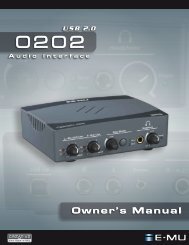
4 - The PatchMix DSP Mixer<br />
Mixer Strip Creation<br />
E-MU Digital Audio System 21<br />
10<br />
+20 dBu<br />
}<br />