STUDIES OF ENERGY RECOVERY LINACS AT ... - CASA
STUDIES OF ENERGY RECOVERY LINACS AT ... - CASA STUDIES OF ENERGY RECOVERY LINACS AT ... - CASA
FIG. 2.2: Schematic of the CEBAF accelerator. from linac to linac. In addition an arc must provide a path length that is equal to an integer multiple of the fundamental RF wavelength to provide proper phasing for beam acceleration. A schematic of the CEBAF machine and the user end stations is depicted in Fig. 2.2. 2.2 Issues and Challenges In principle, the steps to allow for energy recovery in a recirculating linac like CEBAF are straightforward - simply provide a path length differential of 1/2-RF wavelength after the passing through the north and south linacs. Fortunately the design and construction of CEBAF made provisions for future energy upgrades. To that end, several cryomodule slots were left vacant at the end of the north and south linac. In time, cryomodules will be installed in these spaces to increase the beam energy. The 8.25 m slot length is an ideal space to install the two major components 23
FIG. 2.3: Additional hardware installed to energy recover the beam in CEBAF. The phase delay chicane is installed in an empty cryomodule slot denoted as 2L23 and the beam dump is installed in empty cryomodule slot 2L22. An overhead view of the region is given in the upper drawing and a ground level view is on the bottom. required to energy recover the beam in CEBAF, a phase delay chicane and a beam dump and beamline outfitted with appropriate diagnostics. These components were installed in regions of the south linac denoted as 2L22 and 2L23 and are shown in Fig. 2.3. The new hardware did not interfere with CEBAF’s primary function of providing beam to the nuclear physics community. The energy recovery experiment was noninvasive in the sense that with the dipole string of the phase delay chicane deactivated, it remains transparent to standard CEBAF operations. The CEBAF-ER experiment operated with a one-pass up, one-pass down scheme. The electron beam was injected into the north linac at 56 MeV where it was acceler- ated to 556 MeV. The beam traversed arc 1 and then began acceleration through the south linac where it reached a maximum energy of 1056 MeV. Following the south linac, the beam passed through the newly installed phase delay chicane and through arc 2. The chicane generated a path length differential of 1/2-RF wavelength so that 24
- Page 1 and 2: STUDIES OF ENERGY RECOVERY LINACS A
- Page 3 and 4: DEDICATION To my wife Danielle and
- Page 5 and 6: 2 CEBAF with Energy Recovery . . .
- Page 7 and 8: 5.2 HOM Power . . . . . . . . . . .
- Page 9 and 10: ACKNOWLEDGMENTS First and foremost
- Page 11 and 12: 6.1 Summary of the measured effects
- Page 13 and 14: 2.10 Illustration of quadrupole sca
- Page 15 and 16: 5.1 Successive frames in time (prog
- Page 17 and 18: 6.8 A plot of 1/Qeff versus average
- Page 19 and 20: ABSTRACT An energy recovering linac
- Page 21 and 22: CHAPTER 1 Introduction An increasin
- Page 23 and 24: FIG. 1.1: Schematic of a generic li
- Page 25 and 26: FIG. 1.2: A CEBAF 5-cell cavity wit
- Page 27 and 28: The solution to Eq. (1.3) is U(t) =
- Page 29 and 30: y reducing the impedance of HOMs, a
- Page 31 and 32: Despite its success, this method of
- Page 33 and 34: design parameters, most notably ach
- Page 35 and 36: 1.4.2 Machine Optics The second cat
- Page 37 and 38: analytic model elucidates many impo
- Page 39 and 40: CHAPTER 2 CEBAF with Energy Recover
- Page 41: FIG. 2.1: Energy versus average cur
- Page 45 and 46: FIG. 2.4: A picture of the energy r
- Page 47 and 48: dipoles and beam diagnostics such a
- Page 49 and 50: FIG. 2.7: Horizontal (red) and vert
- Page 51 and 52: FIG. 2.8: Illustration of the cryom
- Page 53 and 54: linac and θNL is the RF phase. The
- Page 55 and 56: 2.4 Transverse Emittance One of the
- Page 57 and 58: where σ2 is the rms beam size meas
- Page 59 and 60: eams. The effects of varying the qu
- Page 61 and 62: FIG. 2.12: A typical wire scan near
- Page 63 and 64: quadratic fit and a multiple regres
- Page 65 and 66: ting the data is difficult. Without
- Page 67 and 68: primary source of error is measurin
- Page 69 and 70: identified, although the phase dela
- Page 71 and 72: TABLE 2.3: Comparison of Twiss para
- Page 73 and 74: the results of the fits. The vertic
- Page 75 and 76: FIG. 2.18: Schematic illustrating t
- Page 77 and 78: FIG. 2.19: The GASK signal measured
- Page 79 and 80: FIG. 2.20: The measured normalized
- Page 81 and 82: CHAPTER 3 The Jefferson Laboratory
- Page 83 and 84: FIG. 3.1: Schematic of the 10 kW FE
- Page 85 and 86: FIG. 3.2: Layout of the DC photocat
- Page 87 and 88: accelerating gradient at the front
- Page 89 and 90: eason for making the endloops achro
- Page 91 and 92: FIG. 3.7: Illustration of path leng
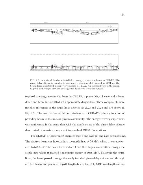
FIG. 2.3: Additional hardware installed to energy recover the beam in CEBAF. The<br />
phase delay chicane is installed in an empty cryomodule slot denoted as 2L23 and the<br />
beam dump is installed in empty cryomodule slot 2L22. An overhead view of the region<br />
is given in the upper drawing and a ground level view is on the bottom.<br />
required to energy recover the beam in CEBAF, a phase delay chicane and a beam<br />
dump and beamline outfitted with appropriate diagnostics. These components were<br />
installed in regions of the south linac denoted as 2L22 and 2L23 and are shown in<br />
Fig. 2.3. The new hardware did not interfere with CEBAF’s primary function of<br />
providing beam to the nuclear physics community. The energy recovery experiment<br />
was noninvasive in the sense that with the dipole string of the phase delay chicane<br />
deactivated, it remains transparent to standard CEBAF operations.<br />
The CEBAF-ER experiment operated with a one-pass up, one-pass down scheme.<br />
The electron beam was injected into the north linac at 56 MeV where it was acceler-<br />
ated to 556 MeV. The beam traversed arc 1 and then began acceleration through the<br />
south linac where it reached a maximum energy of 1056 MeV. Following the south<br />
linac, the beam passed through the newly installed phase delay chicane and through<br />
arc 2. The chicane generated a path length differential of 1/2-RF wavelength so that<br />
24


