STUDIES OF ENERGY RECOVERY LINACS AT ... - CASA
STUDIES OF ENERGY RECOVERY LINACS AT ... - CASA STUDIES OF ENERGY RECOVERY LINACS AT ... - CASA
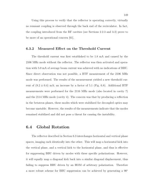
Using this process to verify that the reflector is operating correctly, virtually no remnant coupling is observed through the back end of the recirculator. In fact, the coupling introduced from the RF cavities (see Sections 2.2.3 and 3.3) prove to be more of an operational concern [61]. 6.3.2 Measured Effect on the Threshold Current The threshold current was first established to be 1.8 mA and caused by the 2106 MHz mode without the reflector. The reflector was then activated and opera- tion with 5.0 mA of average beam current was achieved with no indications of BBU. Since direct observation was not possible, a BTF measurement of the 2106 MHz mode was performed. The results of the measurement yielded a new threshold cur- rent of (9.2 ± 0.4) mA; an increase by a factor of 5.1 (Fig. 6.8). Additional BTF measurements were performed for the 2116 MHz mode (also located in cavity 7) and the 2114 MHz mode (cavity 4). The concern was that by producing a reflection in the betatron planes, these modes which were stabilized for decoupled optics may become unstable. However, the results of the measurements indicate that the modes remained stabilized and did not pose a threat for causing the instability. 6.4 Global Rotation The reflector described in Section 6.3 interchanges horizontal and vertical phase spaces, imaging each identically into the other. This will map a horizontal kick into the vertical plane, and a vertical kick to the horizontal plane, and thus is effective for suppressing BBU driven by modes with these specific polarizations. However, it will equally map a diagonal kick back into a similar diagonal displacement, thus failing to suppress BBU driven by an HOM of arbitrary polarization. Therefore a more robust scheme for BBU suppression can be achieved by generating a 90 ◦ 149
FIG. 6.8: A plot of 1/Qeff versus average beam current for the 2106 MHz mode with the local reflector activated. The best fit line is used to determine that the threshold current is 9.2 mA. rotation of the betatron planes from cavity 7 back to itself. The 4×4 recirculation transfer matrix for a 90 ◦ rotation is completely coupled and the off-diagonal 2×2 matrices are of opposite sign ⎛ ⎜ ⎝ 0 M −M 0 ⎞ 150 ⎟ ⎠ (6.11) From Eq. (6.11), M12 = M34 = 0, M32 = −M14 and the threshold current given by Eq. (4.21) is infinite independent of the mode orientation, α. For a single mode the idea is conceptually simple and is illustrated in Fig. 6.9. If on the first pass an offending mode imparts an angular deflection α, to a bunch, then on the second pass (and after a 90 ◦ rotation), the resultant displacement will be orthogonal to the deflection. Thus the bunch will be unable to couple energy to the mode that caused the deflection. A rotation implemented in a two-pass system effectively
- Page 117 and 118: FIG. 4.4: Output from MATBBU showin
- Page 119 and 120: FIG. 4.5: Setup for measuring cavit
- Page 121 and 122: Consequently, depending on the exte
- Page 123 and 124: The projection of the beam displace
- Page 125 and 126: TABLE 4.1: Experimental measurement
- Page 127 and 128: FIG. 4.10: A plot showing the effec
- Page 129 and 130: these cryomodules. Modes from these
- Page 131 and 132: CHAPTER 5 Experimental Measurements
- Page 133 and 134: threshold current - preferably with
- Page 135 and 136: occurred at approximately 2 mA of a
- Page 137 and 138: FIG. 5.5: FFT of a pure 2106.007 MH
- Page 139 and 140: FIG. 5.6: Illustration to show the
- Page 141 and 142: 5.4 Measuring the Threshold Current
- Page 143 and 144: for the HOM-beam system and is deri
- Page 145 and 146: FIG. 5.10: Schematic of the experim
- Page 147 and 148: FIG. 5.12: A plot of 1/Qeff versus
- Page 149 and 150: measured HOMs in zone 3, a BTF meas
- Page 151 and 152: FIG. 5.16: HOM voltage measured fro
- Page 153 and 154: FIG. 5.18: A plot of the three valu
- Page 155 and 156: the beam’s response in regions wh
- Page 157 and 158: CHAPTER 6 BBU Suppression: Beam Opt
- Page 159 and 160: FIG. 6.1: Schematic of a FODO cell
- Page 161 and 162: plane [85]. Equations (6.7) and (6.
- Page 163 and 164: 6.2.3 Discussion The method of poin
- Page 165 and 166: FIG. 6.3: Beam envelopes (horizonta
- Page 167: FIG. 6.6: Beam position monitor rea
- Page 171 and 172: ⎛ ⎞ ⎜ ⎝ 0 0 0 0 0 −1/K 0
- Page 173 and 174: FIG. 6.11: A plot of 1/Qeff versus
- Page 175 and 176: FIG. 6.12: Threshold current for no
- Page 177 and 178: FIG. 6.14: Threshold current utiliz
- Page 179 and 180: TABLE 6.1: Summary of the measured
- Page 181 and 182: CHAPTER 7 BBU Suppression: Feedback
- Page 183 and 184: FIG. 7.1: A schematic of the feedba
- Page 185 and 186: FIG. 7.4: A coaxial 3-stub tuner us
- Page 187 and 188: All of these considerations are con
- Page 189 and 190: FIG. 7.6: Generic layout for a feed
- Page 191 and 192: in Section 4.2.1, however, in the p
- Page 193 and 194: FIG. 7.7: The threshold current as
- Page 195 and 196: FIG. 7.8: Threshold current versus
- Page 197 and 198: FIG. 7.10: The threshold current as
- Page 199 and 200: CHAPTER 8 Conclusions The work pres
- Page 201 and 202: le were experimentally measured. Du
- Page 203 and 204: APPENDIX A The Pillbox Cavity Start
- Page 205 and 206: FIG. A.1: A pillbox cavity exhibiti
- Page 207 and 208: Ez(ρ, φ) = ψ(ρ, φ) = E0Jm(γρ
- Page 209 and 210: FIG. B.1: Relationship of the S-par
- Page 211 and 212: FIG. C.1: Impedance and frequency o
- Page 213 and 214: FIG. C.5: Impedance and frequency o
- Page 215 and 216: BIBLIOGRAPHY [1] M. Tigner, Nuovo C
- Page 217 and 218: [22] L. Merminga, in Proceedings of
Using this process to verify that the reflector is operating correctly, virtually<br />
no remnant coupling is observed through the back end of the recirculator. In fact,<br />
the coupling introduced from the RF cavities (see Sections 2.2.3 and 3.3) prove to<br />
be more of an operational concern [61].<br />
6.3.2 Measured Effect on the Threshold Current<br />
The threshold current was first established to be 1.8 mA and caused by the<br />
2106 MHz mode without the reflector. The reflector was then activated and opera-<br />
tion with 5.0 mA of average beam current was achieved with no indications of BBU.<br />
Since direct observation was not possible, a BTF measurement of the 2106 MHz<br />
mode was performed. The results of the measurement yielded a new threshold cur-<br />
rent of (9.2 ± 0.4) mA; an increase by a factor of 5.1 (Fig. 6.8). Additional BTF<br />
measurements were performed for the 2116 MHz mode (also located in cavity 7)<br />
and the 2114 MHz mode (cavity 4). The concern was that by producing a reflection<br />
in the betatron planes, these modes which were stabilized for decoupled optics may<br />
become unstable. However, the results of the measurements indicate that the modes<br />
remained stabilized and did not pose a threat for causing the instability.<br />
6.4 Global Rotation<br />
The reflector described in Section 6.3 interchanges horizontal and vertical phase<br />
spaces, imaging each identically into the other. This will map a horizontal kick into<br />
the vertical plane, and a vertical kick to the horizontal plane, and thus is effective<br />
for suppressing BBU driven by modes with these specific polarizations. However,<br />
it will equally map a diagonal kick back into a similar diagonal displacement, thus<br />
failing to suppress BBU driven by an HOM of arbitrary polarization. Therefore<br />
a more robust scheme for BBU suppression can be achieved by generating a 90 ◦<br />
149


