High Brightness Electron Beam Diagnostics and their ... - CASA
High Brightness Electron Beam Diagnostics and their ... - CASA High Brightness Electron Beam Diagnostics and their ... - CASA
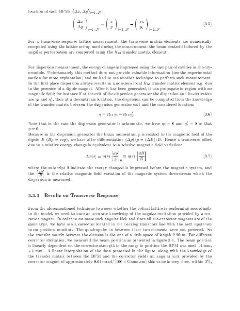
computedusingthelatticeset-upusedduringthemeasurement;thebeamcentroidinducedbythe locationofeachBPMsfx;ygi=1:::N: angularperturbationarecomputedusingtheR12transfermatrixelement. Foratransverseresponselatticemeasurement,thetransversematrixelementsarenumerically xy!i=1:::N= xy!i=1:::N x0 y0!i=1:::N (3.5) ofthetransfermatrixbetweenthedispersiongeneratorexitandtheconsideredlocation: Fordispersionmeasurement,theenergychangeisimpressedusingthelastpairofcavitiesinthecryomodule.Unfortunatelythismethoddoesnotprovidevaluableinformation(seetheexperimental sectionformoreexplanation)andwehadtouseanothertechniquetoperformsuchmeasurement. Intherstplacedispersionalwaysresultsinanon-zerolocalR16transfermatrixelemente.g.due tothepresenceofadipolemagnet.Afterithasbeengenerated,itcanpropagateinregionwithno magneticeld;forinstanceifattheexitofthedispersiongeneratorthedispersionanditsderivative are0and00,thenatadownstreamlocation,thedispersioncanbecomputedfromtheknowledge duetoarelativeenergychangeisequivalenttoarelativemagneticeldvariation: dipoleB(B=ecp),wehaveafterdierentiation(p)=p=(B)=B.Henceatransverseoset Becauseinthedispersiongeneratorthebeammomentumpisrelatedtothemagneticeldofthe Notethatinthecasethedispersiongeneratorisachromatic,wehave0=0and00=0sothat 0. =R110+R1200 (3.6) wherethesubscript0indicatetheenergychangedisimpressedbeforethemagneticsystem,and thehdBiistherelativemagneticeldvariationofthemagneticsystemdownstreamwhichthe dispersionismeasured. x(s)=(s)dp p0(s)dBB (3.7) beampositionmonitor.Thequadrupolesinbetweenthesetwoelementswerenotpowered.So Fromtheaforementionedtechniquetoassesswhethertheopticallatticeisperformingaccordingly tothemodel,weneedtohaveanaccurateknowledgeoftheangularexcitationprovidedbyacorrectormagnet.Inordertoestimatesuchangularkickandsinceallthecorrectormagnetsareofthe sametype,wehaveuseacorrectorlocatedinthebacklegtransportlinewiththenextupstream 3.3.3ResultsonTransverseResponse thetransfermatrixbetweentheBPMandthecorrectoryieldsanangularkickprovidedbythe thetransfermatrixbetweentheelementistheoneofadriftspaceoflength2.80m.Fordierent correctorexcitation,wemeasuredthebeampositionaspresentedingure3.4.Thebeamposition islinearlydependentonthecorrectorstrengthintherangeinpositiontheBPMwasused[-4mm, +4mm].Alinearinterpolationofthedatapresentedinthegure,alongwiththeknowledgeof correctormagnetofapproximately0:64mrad=(100Gauss:cm)thisvalueisveryclose,within3%,
5 4 3 2 Figure3.4:Exampleofcalibrationofacorrector.Theslopeofthelinearinterpolationis 1 0:0183mm=(G:cm)whichcorrespondstoanangulardeectionof6:54rad=(G:cm) 0 −1 −2 −3 −4 alongthebeamline;typicalvalueusedduringtheacquisitionofdierenceorbitmeasurementare ofthecalculatedvaluededucedfromthecorrectormagneticeldmapmeasurement3whichgivea −5 excitationofthecorrector)alltheBPMreadbacksalongthebeamlineareacquiredthreetimes BPMvaluealongthebeamline,insuchawaythatthekickprovideasignicantpositionchange approximately100G:cm.ForagivencorrectorchangeBnom+B,(Bnomisthenominalmagnetic Practically,thecorrectorstrengthissetdevisobylookingattheon-linehistogramplotofthe kickof0:65mrad=(100Gauss:cm) −300 −200 −100 0 100 200 300 Corrector Field Integral (G.cm) oflinearityofthesystem,theBPMreadbackshouldbetheoppositeoftheonemeasuredforthe latteroperationallowtovalidatethemeasurement,sinceforthelattercorrectorsetting,because (toquantifythebeampositionjitter).ThenthecorrectorissettothevalueBnomB.This 2F04Vand2F08V).Thecorrectorsarechosensothattherelativebetatronphaseadvancebetween forthehorizontalplane(2F00H,2F04Hand2F08H)andthreefortheverticalplane(2F00V, probedierentpartofthelattice.Inourpresentstudy,weusesixdierentcorrectors:three zeroforalltheBPMs. Theuseofonlyonecorrectortostudytheresponseofthelatticeisnotsucientsinceitonly\probe" thelatticeatlocationthathavearelativebetatronphaseadvanceofapproximately90deg4.Hence itispreferabletouseatleasttwocorrectorsseparatedbytheproperphaseadvancesothatthey rstmeasurement.Thereforethecomputationofthesumofthetwomeasurementsshouldgive istherelativebetatronphaseadvancebetweenthepointssands0. 3G.H.Biallas,privatecommunication,June99 4InthegeneralTwisstransfermatrixformalismonehas:Rs0!s 12=p(s)(s0)sin()where=(s)(s0) ∆ x 2.80 meters downstream (mm)
- Page 1 and 2: HighBrightnessElectronBeamDiagnosti
- Page 3 and 4: eratedupto48MeVpriortothelasingsyst
- Page 5 and 6: IthanktheCEBAFmachineoperators,with
- Page 7 and 8: 3.4MeasurementoftheLongitudinalResp
- Page 9 and 10: 5.6ZerophasingTechniqueforBunchLeng
- Page 11 and 12: ListofTables 3.2Comparisonofcoecien
- Page 13 and 14: ListofFigures 1.1Comparisonoftheexp
- Page 15 and 16: 3.11Momentumcompactionandnonlinearm
- Page 17 and 18: 4.18Overviewofthephasespacesampling
- Page 19 and 20: 5.16Interferogrammeasuredfordierent
- Page 21 and 22: 6.10Comparisonofthermstransversehor
- Page 23 and 24: Chapter1 UVdomainandareplannedtogen
- Page 25 and 26: space-chargeinthelowenergyregime,an
- Page 27 and 28: !Vjitsthevelocity,and!Xjisthepositi
- Page 29 and 30: equation boundarybetweenvacuumandam
- Page 31 and 32: 10 0 0.1 0.2 0.3 0.4 0.5 0.6 0.7 0.
- Page 33 and 34: 1.0 0.8 0.6 0.4 0.2 E=10 MeV E=42 M
- Page 35 and 36: 00000000000000000000000000000000000
- Page 37 and 38: harmonicwithproperchoiceoftheKvalue
- Page 39 and 40: Bu(rms)0.28T ParameterValueUnit Nu
- Page 41: 2.7TheJeersonLabIRproject usedasexp
- Page 44 and 45: Study TheFELdriveraccelerator:Latti
- Page 46 and 47: ParameterValue x -0.178 x(m) 8.331
- Page 48 and 49: Thepurposeofmeasuringthetransverser
- Page 52 and 53: etatronexcitationaspicturedingure3.
- Page 54 and 55: ∆ x (mm), Corrector 0F00H ∆ x (
- Page 56 and 57: 1 0.5 0 spreadoftheparticlewassetto
- Page 58 and 59: 2 1 −5 −3 −1 1 3 5 k (m q −
- Page 60 and 61: Experimentallythecalibrationcoecien
- Page 62 and 63: tioned.FromthetransferfunctioninFig
- Page 64 and 65: Pickup Experiment #2 #3 #4 Simulati
- Page 66 and 67: Fromthesebothmeasurementitispossibl
- Page 68 and 69: . . . . . . . . . . . . . . . . . .
- Page 70 and 71: 10 5 Sext. ON Figure3.20:Eectofthes
- Page 72 and 73: spaceabeamthatconsistsofNparticles,
- Page 74 and 75: Asforthegeometricemittanceonecanden
- Page 76 and 77: (a) ceramic radiator beam x-wire be
- Page 78 and 79: and validundertheassumptionofaunifo
- Page 80 and 81: 1000 900 800 700 Figure4.4:Steadyst
- Page 82 and 83: Fraction of Beam enclosed within (%
- Page 84 and 85: 5 2 2 3 4 5 6 7 8 9 10 0 10 5 2 Foi
- Page 86 and 87: Actuator Inserts Foil and Mirror CI
- Page 88 and 89: shortterm,touseasbeamdensitymonitor
- Page 90 and 91: Alongwiththeseimplementedoperations
- Page 92 and 93: whereiistheerrorontheithbeamsizemea
- Page 94 and 95: Let'sassumethethinlensapproximation
- Page 96 and 97: obtainedviathestatisticalanalysis.T
- Page 98 and 99: 20 18 16 . 14 . 12 . Figure4.14:Rel
computedusingthelatticeset-upusedduringthemeasurement;thebeamcentroidinducedbythe locationofeachBPMsfx;ygi=1:::N:<br />
angularperturbationarecomputedusingtheR12transfermatrixelement. Foratransverseresponselatticemeasurement,thetransversematrixelementsarenumerically xy!i=1:::N= xy!i=1:::N x0 y0!i=1:::N (3.5)<br />
ofthetransfermatrixbetweenthedispersiongeneratorexit<strong>and</strong>theconsideredlocation: Fordispersionmeasurement,theenergychangeisimpressedusingthelastpairofcavitiesinthecryomodule.Unfortunatelythismethoddoesnotprovidevaluableinformation(seetheexperimental sectionformoreexplanation)<strong>and</strong>wehadtouseanothertechniquetoperformsuchmeasurement. Intherstplacedispersionalwaysresultsinanon-zerolocalR16transfermatrixelemente.g.due tothepresenceofadipolemagnet.Afterithasbeengenerated,itcanpropagateinregionwithno magneticeld;forinstanceifattheexitofthedispersiongeneratorthedispersion<strong>and</strong>itsderivative are0<strong>and</strong>00,thenatadownstreamlocation,thedispersioncanbecomputedfromtheknowledge<br />
duetoarelativeenergychangeisequivalenttoarelativemagneticeldvariation: dipoleB(B=ecp),wehaveafterdierentiation(p)=p=(B)=B.Henceatransverseoset Becauseinthedispersiongeneratorthebeammomentumpisrelatedtothemagneticeldofthe Notethatinthecasethedispersiongeneratorisachromatic,wehave0=0<strong>and</strong>00=0sothat 0. =R110+R1200 (3.6)<br />
wherethesubscript0indicatetheenergychangedisimpressedbeforethemagneticsystem,<strong>and</strong> thehdBiistherelativemagneticeldvariationofthemagneticsystemdownstreamwhichthe dispersionismeasured. x(s)=(s)dp p0(s)dBB (3.7)<br />
beampositionmonitor.Thequadrupolesinbetweenthesetwoelementswerenotpowered.So Fromtheaforementionedtechniquetoassesswhethertheopticallatticeisperformingaccordingly tothemodel,weneedtohaveanaccurateknowledgeoftheangularexcitationprovidedbyacorrectormagnet.Inordertoestimatesuchangularkick<strong>and</strong>sinceallthecorrectormagnetsareofthe sametype,wehaveuseacorrectorlocatedinthebacklegtransportlinewiththenextupstream 3.3.3ResultsonTransverseResponse<br />
thetransfermatrixbetweentheBPM<strong>and</strong>thecorrectoryieldsanangularkickprovidedbythe thetransfermatrixbetweentheelementistheoneofadriftspaceoflength2.80m.Fordierent correctorexcitation,wemeasuredthebeampositionaspresentedingure3.4.Thebeamposition islinearlydependentonthecorrectorstrengthintherangeinpositiontheBPMwasused[-4mm, +4mm].Alinearinterpolationofthedatapresentedinthegure,alongwiththeknowledgeof correctormagnetofapproximately0:64mrad=(100Gauss:cm)thisvalueisveryclose,within3%,


