High Brightness Electron Beam Diagnostics and their ... - CASA
High Brightness Electron Beam Diagnostics and their ... - CASA High Brightness Electron Beam Diagnostics and their ... - CASA
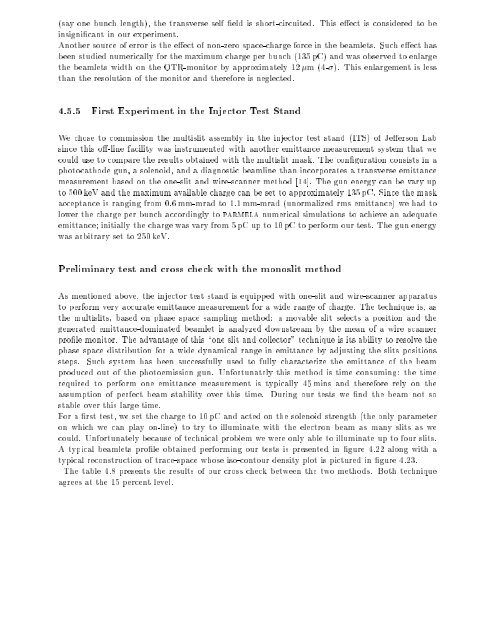
(sayonebunchlength),thetransverseselfeldisshort-circuited.Thiseectisconsideredtobe Anothersourceoferroristheeectofnon-zerospace-chargeforceinthebeamlets.Sucheecthas insignicantinourexperiment. beenstudiednumericallyforthemaximumchargeperbunch(135pC)andwasobservedtoenlarge Wechosetocommissionthemultislitassemblyintheinjectorteststand(ITS)ofJeersonLab thantheresolutionofthemonitorandthereforeisneglected. 4.5.5FirstExperimentintheInjectorTestStand thebeamletswidthontheOTR-monitorbyapproximately12m(4-).Thisenlargementisless photocathodegun,asolenoid,andadiagnosticbeamlinethanincorporatesatransverseemittance measurementbasedontheone-slitandwire-scannermethod[14].Thegunenergycanbevaryup to500keVandthemaximumavailablechargecanbesettoapproximately135pC.Sincethemask acceptanceisrangingfrom0:6mm-mradto1:1mm-mrad(unormalizedrmsemittance)wehadto couldusetocomparetheresultsobtainedwiththemultislitmask.Thecongurationconsistsina sincethiso-linefacilitywasinstrumentedwithanotheremittancemeasurementsystemthatwe wasarbitrarysetto250keV. Preliminarytestandcrosscheckwiththemonoslitmethod emittance;initiallythechargewasvaryfrom5pCupto10pCtoperformourtest.Thegunenergy lowerthechargeperbunchaccordinglytoparmelanumericalsimulationstoachieveanadequate generatedemittance-dominatedbeamletisanalyzeddownstreambythemeanofawirescanner themultislits,basedonphasespacesamplingmethod:amovableslitselectsapositionandthe prolemonitor.Theadvantageofthis\oneslitandcollector"techniqueisitsabilitytoresolvethe phasespacedistributionforawidedynamicalrangeinemittancebyadjustingtheslitspositions toperformveryaccurateemittancemeasurementforawiderangeofcharge.Thetechniqueis,as steps.Suchsystemhasbeensuccessfullyusedtofullycharacterizetheemittanceofthebeam producedoutofthephotoemissiongun.Unfortunatelythismethodistimeconsuming:thetime Asmentionedabove,theinjectorteststandisequippedwithone-slitandwire-scannerapparatus requiredtoperformoneemittancemeasurementistypically45minsandthereforerelyonthe assumptionofperfectbeamstabilityoverthistime.Duringourtestswendthebeamnotso could.Unfortunatelybecauseoftechnicalproblemwewereonlyabletoilluminateuptofourslits. stableoverthislargetime. Forarsttest,wesetthechargeto10pCandactedonthesolenoidstrength(theonlyparameter onwhichwecanplayon-line)totrytoilluminatewiththeelectronbeamasmanyslitsaswe Atypicalbeamletsproleobtainedperformingourtestsispresentedingure4.22alongwitha agreesatthe15percentlevel. typicalreconstructionoftrace-spacewhoseiso-contourdensityplotispicturedingure4.23. Thetable4.8presentstheresultsofourcrosscheckbetweenthetwomethods.Bothtechnique
180 8 160 6 Figure4.22:Anexampleof2Dbeamdistributionontheanalyzerscreendownstreamthemultislit 4 140 mask.Theprojectionontothex-axisisalsodisplayed. 2 120 0 100 −2 80 −4 60 −6 40 Table4.8:Comparisonofthermstransverseemittancemeasurementperformedwiththemultislits ~"x(mm-mrad)~"x(mm-mrad) Dierence(%) −8 andtheone-slitandone-harptechniques. 0.4669 0.5607 0.5594 multislitmethodone-slit-oneharpmethod 0.5071 0.5070 0.4859 811 15 −10 20 −5 −4 −3 −2 −1 0 1 2 3 4 5 x (mm) MeasurementofEmittanceintheInjectorTestStand Wethenvariedthesolenoidstrengthfrom237:5Gupto307:5Gtoseehowwasevolvingthe around280G(seeFig.4.24)asobservedinnumericalsimulation.The-functionpresentsas emittancevaluefordierentsettingsoftherstsolenoid.Theemittancepresentsagapatvalues Chapter1).Thenumberofproducedelectronsdependsontheselectedwidthforthemacropulse. thenumberofphotonwasstillhighenoughtoproducedunwantedelectrons(seeourcommentin theoutputoftheswitchwhenitiscloseoropen)wasnotoptimizedandthenevenwhenclosed, factthiswasduetoproblemwiththeopticalswitchofthephotocathodelaseryieldingalightleak creatinglowemittance\ghostpulses":extinctionratio(ratiobetweentheintensityofthelightat expectedaminimumcorrespondingtothebeamwaist.Chargewasvariedusingthelaserattenuator andthebunchchargewasmeasuredusingabeamdumpedequippedwithaFaradaycup.Asitcan beseeningure4.25below,theemittancewasfoundtobedependentonthemacropulsewidth.In y (mm) 10
- Page 60 and 61: Experimentallythecalibrationcoecien
- Page 62 and 63: tioned.FromthetransferfunctioninFig
- Page 64 and 65: Pickup Experiment #2 #3 #4 Simulati
- Page 66 and 67: Fromthesebothmeasurementitispossibl
- Page 68 and 69: . . . . . . . . . . . . . . . . . .
- Page 70 and 71: 10 5 Sext. ON Figure3.20:Eectofthes
- Page 72 and 73: spaceabeamthatconsistsofNparticles,
- Page 74 and 75: Asforthegeometricemittanceonecanden
- Page 76 and 77: (a) ceramic radiator beam x-wire be
- Page 78 and 79: and validundertheassumptionofaunifo
- Page 80 and 81: 1000 900 800 700 Figure4.4:Steadyst
- Page 82 and 83: Fraction of Beam enclosed within (%
- Page 84 and 85: 5 2 2 3 4 5 6 7 8 9 10 0 10 5 2 Foi
- Page 86 and 87: Actuator Inserts Foil and Mirror CI
- Page 88 and 89: shortterm,touseasbeamdensitymonitor
- Page 90 and 91: Alongwiththeseimplementedoperations
- Page 92 and 93: whereiistheerrorontheithbeamsizemea
- Page 94 and 95: Let'sassumethethinlensapproximation
- Page 96 and 97: obtainedviathestatisticalanalysis.T
- Page 98 and 99: 20 18 16 . 14 . 12 . Figure4.14:Rel
- Page 100 and 101: 100 10 −3 10 −2 10 −1 10 that
- Page 102 and 103: multislits mask (copper) Aluminum F
- Page 104: TheReductionoftheSpaceChargeconditi
- Page 107 and 108: . . . . . . . . . . . . . . . . . .
- Page 109: Table4.7:Typicalsystematicerroronem
- Page 113 and 114: 4.0 3.5 3.0 2.5 Figure4.24:Emittanc
- Page 115 and 116: Characterization LongitudinalPhaseS
- Page 117 and 118: concentrateonthebeamparametersinthe
- Page 119 and 120: 1.1 1 mrad 0.9 5 mrad mainlyduetoth
- Page 121 and 122: Population Population 100000 90000
- Page 123 and 124: Theequation5.8yields: f()=jZ+1 11Xn
- Page 125 and 126: presentanoutlineofthisproofbelow,an
- Page 127 and 128: contrastintheCEBAFmachine,varyingas
- Page 129 and 130: 1.5 1 correspondtothevarianceofveco
- Page 131 and 132: Ε’ 2 B Mirror M 2 Ε2 Polarizer
- Page 133 and 134: FinallyitisinterestingtonotethatFou
- Page 135 and 136: Itsautocorrelationis:S(z)=8>:(1=w2)
- Page 137 and 138: drivelaserwhereasin(A),suchoperatio
- Page 139 and 140: expansionoftheBFFderivedinthischapt
- Page 141 and 142: Asarstapproximation,wecanestimatetr
- Page 143 and 144: errorpropagation8theoryappliedonEqn
- Page 145 and 146: inducedbyspacechargeisnotaconcernin
- Page 147 and 148: Golay Cell Signal (V) Golay Cell Si
- Page 149 and 150: Golay Cell Ouput (V) Golay Cell Oup
- Page 151 and 152: 150 100 5 4 Figure5.19:Energyspectr
- Page 153 and 154: Figure5.23:picturaleectoflongitudin
- Page 155 and 156: . .. .. . .. . . .. . .. . . .. . .
- Page 157 and 158: σ x (m) x 10−3 5 4 3 2 1 0 0 5 1
- Page 159 and 160: BeamDynamicsStudies Chapter6 undula
(sayonebunchlength),thetransverseselfeldisshort-circuited.Thiseectisconsideredtobe Anothersourceoferroristheeectofnon-zerospace-chargeforceinthebeamlets.Sucheecthas insignicantinourexperiment. beenstudiednumericallyforthemaximumchargeperbunch(135pC)<strong>and</strong>wasobservedtoenlarge<br />
Wechosetocommissionthemultislitassemblyintheinjectortestst<strong>and</strong>(ITS)ofJeersonLab thantheresolutionofthemonitor<strong>and</strong>thereforeisneglected. 4.5.5FirstExperimentintheInjectorTestSt<strong>and</strong> thebeamletswidthontheOTR-monitorbyapproximately12m(4-).Thisenlargementisless<br />
photocathodegun,asolenoid,<strong>and</strong>adiagnosticbeamlinethanincorporatesatransverseemittance measurementbasedontheone-slit<strong>and</strong>wire-scannermethod[14].Thegunenergycanbevaryup to500keV<strong>and</strong>themaximumavailablechargecanbesettoapproximately135pC.Sincethemask acceptanceisrangingfrom0:6mm-mradto1:1mm-mrad(unormalizedrmsemittance)wehadto couldusetocomparetheresultsobtainedwiththemultislitmask.Thecongurationconsistsina sincethiso-linefacilitywasinstrumentedwithanotheremittancemeasurementsystemthatwe<br />
wasarbitrarysetto250keV. Preliminarytest<strong>and</strong>crosscheckwiththemonoslitmethod emittance;initiallythechargewasvaryfrom5pCupto10pCtoperformourtest.Thegunenergy lowerthechargeperbunchaccordinglytoparmelanumericalsimulationstoachieveanadequate<br />
generatedemittance-dominatedbeamletisanalyzeddownstreambythemeanofawirescanner themultislits,basedonphasespacesamplingmethod:amovableslitselectsaposition<strong>and</strong>the prolemonitor.Theadvantageofthis\oneslit<strong>and</strong>collector"techniqueisitsabilitytoresolvethe phasespacedistributionforawidedynamicalrangeinemittancebyadjustingtheslitspositions toperformveryaccurateemittancemeasurementforawiderangeofcharge.Thetechniqueis,as steps.Suchsystemhasbeensuccessfullyusedtofullycharacterizetheemittanceofthebeam producedoutofthephotoemissiongun.Unfortunatelythismethodistimeconsuming:thetime Asmentionedabove,theinjectortestst<strong>and</strong>isequippedwithone-slit<strong>and</strong>wire-scannerapparatus<br />
requiredtoperformoneemittancemeasurementistypically45mins<strong>and</strong>thereforerelyonthe assumptionofperfectbeamstabilityoverthistime.Duringourtestswendthebeamnotso could.Unfortunatelybecauseoftechnicalproblemwewereonlyabletoilluminateuptofourslits. stableoverthislargetime. Forarsttest,wesetthechargeto10pC<strong>and</strong>actedonthesolenoidstrength(theonlyparameter onwhichwecanplayon-line)totrytoilluminatewiththeelectronbeamasmanyslitsaswe Atypicalbeamletsproleobtainedperformingourtestsispresentedingure4.22alongwitha agreesatthe15percentlevel.<br />
typicalreconstructionoftrace-spacewhoseiso-contourdensityplotispicturedingure4.23. Thetable4.8presentstheresultsofourcrosscheckbetweenthetwomethods.Bothtechnique


