Channel Estimation in OFDM System Based on the Linear ...
Channel Estimation in OFDM System Based on the Linear ...
Channel Estimation in OFDM System Based on the Linear ...

You also want an ePaper? Increase the reach of your titles
YUMPU automatically turns print PDFs into web optimized ePapers that Google loves.
18th Telecommunicati<strong>on</strong>s forum TELFOR 2010 Serbia, Belgrade, November 23-25, 2010.<br />
<br />
<br />
Abstract — In this paper, we propose a new channel<br />
estimati<strong>on</strong> algorithm based <strong>on</strong> <strong>the</strong> tra<str<strong>on</strong>g>in</str<strong>on</strong>g><str<strong>on</strong>g>in</str<strong>on</strong>g>g data for<br />
orthog<strong>on</strong>al frequency divisi<strong>on</strong> multiplex<str<strong>on</strong>g>in</str<strong>on</strong>g>g (<str<strong>on</strong>g>OFDM</str<strong>on</strong>g>) system<br />
<str<strong>on</strong>g>in</str<strong>on</strong>g> fast fad<str<strong>on</strong>g>in</str<strong>on</strong>g>g channel. In this method, channel frequency<br />
resp<strong>on</strong>se (CFR) is estimated. In <strong>the</strong> first step, channel<br />
resp<strong>on</strong>se is estimated at pilot subcarriers by last square<br />
method, and <strong>the</strong>n primary whole CFR is obta<str<strong>on</strong>g>in</str<strong>on</strong>g>ed by l<str<strong>on</strong>g>in</str<strong>on</strong>g>ear<br />
<str<strong>on</strong>g>in</str<strong>on</strong>g>terpolati<strong>on</strong>. In <strong>the</strong> sec<strong>on</strong>d step, <strong>the</strong> effect of noise <strong>on</strong><br />
estimated channel is reduced by us<str<strong>on</strong>g>in</str<strong>on</strong>g>g FFT process<str<strong>on</strong>g>in</str<strong>on</strong>g>g and<br />
<strong>the</strong>n transmitted data is detected. For <str<strong>on</strong>g>in</str<strong>on</strong>g>creas<str<strong>on</strong>g>in</str<strong>on</strong>g>g accuracy of<br />
channel estimati<strong>on</strong>, detected data is modulated aga<str<strong>on</strong>g>in</str<strong>on</strong>g>. Then<br />
by us<str<strong>on</strong>g>in</str<strong>on</strong>g>g received signal <str<strong>on</strong>g>in</str<strong>on</strong>g> receiver and new modulated data,<br />
CFR is estimated anew and is passed from noise reduc<str<strong>on</strong>g>in</str<strong>on</strong>g>g<br />
algorithm. And f<str<strong>on</strong>g>in</str<strong>on</strong>g>ally, data is detected aga<str<strong>on</strong>g>in</str<strong>on</strong>g>. This process is<br />
d<strong>on</strong>e about three or four times to reduce <strong>the</strong> effect of noise<br />
adequately. Computer simulati<strong>on</strong>s dem<strong>on</strong>strate that<br />
proposed method improves bit error rate (BER) and mean<br />
square error (MSE) compared to usual estimati<strong>on</strong> methods.<br />
Keywords — <str<strong>on</strong>g>Channel</str<strong>on</strong>g> <str<strong>on</strong>g>Estimati<strong>on</strong></str<strong>on</strong>g>, Decisi<strong>on</strong> Feedback, FFT,<br />
<str<strong>on</strong>g>OFDM</str<strong>on</strong>g>.<br />
W<br />
<str<strong>on</strong>g>Channel</str<strong>on</strong>g> <str<strong>on</strong>g>Estimati<strong>on</strong></str<strong>on</strong>g> <str<strong>on</strong>g>in</str<strong>on</strong>g> <str<strong>on</strong>g>OFDM</str<strong>on</strong>g> <str<strong>on</strong>g>System</str<strong>on</strong>g> <str<strong>on</strong>g>Based</str<strong>on</strong>g><br />
<strong>on</strong> <strong>the</strong> L<str<strong>on</strong>g>in</str<strong>on</strong>g>ear Interpolati<strong>on</strong>, FFT and<br />
Decisi<strong>on</strong> Feedback<br />
First R. Hajizadeh, Sec<strong>on</strong>d K. Mohamedpor, and Third M.R. Tarihi<br />
I. INTRODUCTION<br />
IRELESS communicati<strong>on</strong> and transmitt<str<strong>on</strong>g>in</str<strong>on</strong>g>g data have<br />
many demands <strong>the</strong>se days and are used <str<strong>on</strong>g>in</str<strong>on</strong>g> many<br />
applicati<strong>on</strong>s. Wireless communicati<strong>on</strong>s have many<br />
problems and restricti<strong>on</strong>s. <str<strong>on</strong>g>Channel</str<strong>on</strong>g> estimati<strong>on</strong> and<br />
destructi<strong>on</strong> by channel, power limitati<strong>on</strong> of transmitted<br />
data, complexity of mobile receivers, band width<br />
limitati<strong>on</strong> that should be distributed between some users,<br />
are some of <strong>the</strong>se problems. Am<strong>on</strong>g of wireless<br />
techniques, orthog<strong>on</strong>al frequency divisi<strong>on</strong> multiplex<str<strong>on</strong>g>in</str<strong>on</strong>g>g<br />
(<str<strong>on</strong>g>OFDM</str<strong>on</strong>g>) has many advantages and especially is noticed <str<strong>on</strong>g>in</str<strong>on</strong>g><br />
frequency selective Rayleigh channels. <str<strong>on</strong>g>OFDM</str<strong>on</strong>g> is a general<br />
technique <str<strong>on</strong>g>in</str<strong>on</strong>g> signal transmissi<strong>on</strong> <strong>on</strong> <strong>the</strong> wireless<br />
communicati<strong>on</strong>. This technique c<strong>on</strong>verts a frequency<br />
selective channel to a collecti<strong>on</strong> of flat frequency selective<br />
sub-channel that leads to simplicity of receiver structure<br />
[1]. In <strong>the</strong>se systems, <str<strong>on</strong>g>in</str<strong>on</strong>g>ter-symbol <str<strong>on</strong>g>in</str<strong>on</strong>g>terference (ISI) can<br />
be removed by us<str<strong>on</strong>g>in</str<strong>on</strong>g>g of cyclic prefix (CP). Cyclic prefix is<br />
<str<strong>on</strong>g>in</str<strong>on</strong>g>serted between c<strong>on</strong>secutive transmitted blocks and<br />
First R. Hajizadeh is with M. Ashtar University of Technology,<br />
Tehran, Iran (ph<strong>on</strong>e: 0098-0121-3262591; e-mail:<br />
hajizadeh_63@yahoo.com).<br />
Corresp<strong>on</strong>d<str<strong>on</strong>g>in</str<strong>on</strong>g>g Sec<strong>on</strong>d K. Mohamedpor is now with Faculty of<br />
Electrical Eng<str<strong>on</strong>g>in</str<strong>on</strong>g>eer<str<strong>on</strong>g>in</str<strong>on</strong>g>g, K.N Toosi University of Technology, Tehran,<br />
Iran; (e-mail: kmpour@ kntu.ac.ir).<br />
Third M.R. Tariti is with M. Ashtar University of Technology, Tehran,<br />
Iran<br />
484<br />
should be <str<strong>on</strong>g>in</str<strong>on</strong>g>creased bey<strong>on</strong>d <strong>the</strong> maximum delay expansi<strong>on</strong><br />
of channel. A good del<str<strong>on</strong>g>in</str<strong>on</strong>g>eati<strong>on</strong> of this parameter leads to<br />
simpler channel synchr<strong>on</strong>izati<strong>on</strong> and <strong>the</strong> effect of channel<br />
appears as a simpler scalar multiplicati<strong>on</strong> <str<strong>on</strong>g>in</str<strong>on</strong>g> <strong>the</strong> frequency<br />
doma<str<strong>on</strong>g>in</str<strong>on</strong>g>. Hence each subcarrier is attenuated by <strong>the</strong><br />
corresp<strong>on</strong>d<str<strong>on</strong>g>in</str<strong>on</strong>g>g narrowband sub-channel coefficient. We<br />
use this property to estimate channel <str<strong>on</strong>g>in</str<strong>on</strong>g> frequency doma<str<strong>on</strong>g>in</str<strong>on</strong>g>.<br />
In <str<strong>on</strong>g>OFDM</str<strong>on</strong>g> systems, detecti<strong>on</strong> of transmitted data and<br />
capacity of system highly depend <strong>on</strong> channel state<br />
<str<strong>on</strong>g>in</str<strong>on</strong>g>formati<strong>on</strong> (CSI) <str<strong>on</strong>g>in</str<strong>on</strong>g> transmitter and receiver. In o<strong>the</strong>r<br />
word cod<str<strong>on</strong>g>in</str<strong>on</strong>g>g, modulati<strong>on</strong> and <str<strong>on</strong>g>in</str<strong>on</strong>g>terference preventi<strong>on</strong><br />
methods can be applied <str<strong>on</strong>g>in</str<strong>on</strong>g> <strong>the</strong>se systems by knowledge of<br />
channel characteristics. If channel is estimated accurately,<br />
undesirable effects <strong>on</strong> channel resp<strong>on</strong>se will be<br />
compensated.<br />
In recent years, several channel estimati<strong>on</strong> methods are<br />
proposed. C<strong>on</strong>sider<str<strong>on</strong>g>in</str<strong>on</strong>g>g of <strong>the</strong>se methods shows that<br />
achiev<str<strong>on</strong>g>in</str<strong>on</strong>g>g more accuracy leads to more complexity. So it<br />
seems necessary to propose a simple and precise method.<br />
The CSI can be obta<str<strong>on</strong>g>in</str<strong>on</strong>g>ed through two methods: 1) bl<str<strong>on</strong>g>in</str<strong>on</strong>g>d<br />
channel estimati<strong>on</strong> 2) tra<str<strong>on</strong>g>in</str<strong>on</strong>g><str<strong>on</strong>g>in</str<strong>on</strong>g>g-based channel estimati<strong>on</strong>.<br />
Bl<str<strong>on</strong>g>in</str<strong>on</strong>g>d channel estimati<strong>on</strong> explores <strong>the</strong> statistical<br />
<str<strong>on</strong>g>in</str<strong>on</strong>g>formati<strong>on</strong> of channel and certa<str<strong>on</strong>g>in</str<strong>on</strong>g> properties of<br />
transmitted signal and needs a large amount of data. Hence<br />
this method isn’t proper <str<strong>on</strong>g>in</str<strong>on</strong>g> fast fad<str<strong>on</strong>g>in</str<strong>on</strong>g>g channels. Tra<str<strong>on</strong>g>in</str<strong>on</strong>g><str<strong>on</strong>g>in</str<strong>on</strong>g>gbased<br />
channel estimati<strong>on</strong> is based <strong>on</strong> <strong>the</strong> tra<str<strong>on</strong>g>in</str<strong>on</strong>g><str<strong>on</strong>g>in</str<strong>on</strong>g>g data,<br />
which is <str<strong>on</strong>g>in</str<strong>on</strong>g>serted <str<strong>on</strong>g>in</str<strong>on</strong>g>to ma<str<strong>on</strong>g>in</str<strong>on</strong>g> data, sent at <strong>the</strong> transmitter and<br />
known a priori at <strong>the</strong> receiver [2].<br />
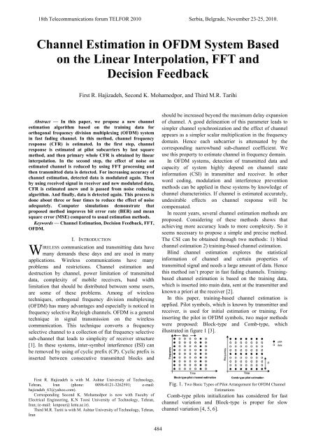
In this paper, tra<str<strong>on</strong>g>in</str<strong>on</strong>g><str<strong>on</strong>g>in</str<strong>on</strong>g>g-based channel estimati<strong>on</strong> is<br />
applied. Pilot symbols, which is known by transmitter and<br />
receiver, is used for <str<strong>on</strong>g>in</str<strong>on</strong>g>itial estimati<strong>on</strong> or tra<str<strong>on</strong>g>in</str<strong>on</strong>g><str<strong>on</strong>g>in</str<strong>on</strong>g>g. For<br />
<str<strong>on</strong>g>in</str<strong>on</strong>g>sert<str<strong>on</strong>g>in</str<strong>on</strong>g>g <strong>the</strong> pilot <str<strong>on</strong>g>in</str<strong>on</strong>g> <str<strong>on</strong>g>OFDM</str<strong>on</strong>g> symbols, two major methods<br />
were proposed: Block-type and Comb-type, which<br />
illustrated <str<strong>on</strong>g>in</str<strong>on</strong>g> figure 1 [3].<br />
Fig. 1. Two Basic Types of Pilot Arrangement for <str<strong>on</strong>g>OFDM</str<strong>on</strong>g> <str<strong>on</strong>g>Channel</str<strong>on</strong>g><br />
<str<strong>on</strong>g>Estimati<strong>on</strong></str<strong>on</strong>g>s<br />
Comb-type pilots <str<strong>on</strong>g>in</str<strong>on</strong>g>itializati<strong>on</strong> has c<strong>on</strong>sidered for fast<br />
channel variati<strong>on</strong> and Block-type is proper for slow<br />
channel variati<strong>on</strong> [4, 5, 6].
In tra<str<strong>on</strong>g>in</str<strong>on</strong>g><str<strong>on</strong>g>in</str<strong>on</strong>g>g-based channel estimati<strong>on</strong>, two usual<br />
algorithms exist to obta<str<strong>on</strong>g>in</str<strong>on</strong>g> channel coefficients <str<strong>on</strong>g>in</str<strong>on</strong>g> pilot<br />
subcarriers: 1) m<str<strong>on</strong>g>in</str<strong>on</strong>g>imum mean square error (MMSE), 2)<br />
Least Square (LS) [7].<br />
Least square has lower complexity and is simple and<br />
doesn’t need to statistical <str<strong>on</strong>g>in</str<strong>on</strong>g>formati<strong>on</strong> of channel and<br />
noise; but its accuracy is lower than MMSE <str<strong>on</strong>g>in</str<strong>on</strong>g> frequency<br />
selective channels. MMSE method is resistant aga<str<strong>on</strong>g>in</str<strong>on</strong>g>st<br />
Doppler effects <str<strong>on</strong>g>in</str<strong>on</strong>g> multipath channels, but needs to<br />
calculate covariance matrix and <str<strong>on</strong>g>in</str<strong>on</strong>g>verse matrix and<br />
statistical <str<strong>on</strong>g>in</str<strong>on</strong>g>formati<strong>on</strong> of noise should be known at<br />
receiver; hence its complexity is high [8]. In this paper,<br />
lower complexity is important for us, so we use LS<br />
method.<br />
In this paper, channel frequency resp<strong>on</strong>se (CFR) is<br />
estimated for <str<strong>on</strong>g>OFDM</str<strong>on</strong>g> systems <str<strong>on</strong>g>in</str<strong>on</strong>g> fast fad<str<strong>on</strong>g>in</str<strong>on</strong>g>g channels. At<br />
first channel coefficients <str<strong>on</strong>g>in</str<strong>on</strong>g> pilot subcarriers are calculated<br />
by us<str<strong>on</strong>g>in</str<strong>on</strong>g>g LS algorithm. Then whole CFR is obta<str<strong>on</strong>g>in</str<strong>on</strong>g>ed by<br />
l<str<strong>on</strong>g>in</str<strong>on</strong>g>ear <str<strong>on</strong>g>in</str<strong>on</strong>g>terpolati<strong>on</strong>. In next step, <strong>the</strong> noise effect <strong>on</strong> <strong>the</strong><br />
estimated channel is reduced by us<str<strong>on</strong>g>in</str<strong>on</strong>g>g discrete Fourier<br />
transform (DFT) process<str<strong>on</strong>g>in</str<strong>on</strong>g>g and transmitted data is<br />
detected. Then for enhanc<str<strong>on</strong>g>in</str<strong>on</strong>g>g accuracy of channel<br />
estimati<strong>on</strong>, detected data is modulated <str<strong>on</strong>g>in</str<strong>on</strong>g> receiver aga<str<strong>on</strong>g>in</str<strong>on</strong>g>,<br />
and channel is estimated by us<str<strong>on</strong>g>in</str<strong>on</strong>g>g new modulated data and<br />
received signal and is passed from noise reduc<str<strong>on</strong>g>in</str<strong>on</strong>g>g<br />
algorithm anew. And f<str<strong>on</strong>g>in</str<strong>on</strong>g>ally transmitted data is detected<br />
aga<str<strong>on</strong>g>in</str<strong>on</strong>g>. This process<str<strong>on</strong>g>in</str<strong>on</strong>g>g has to be repeated three or four<br />
times to reduce <strong>the</strong> effect of noise adequately. Computer<br />
simulati<strong>on</strong>s show that proposed method improved<br />
performance compared to Spl<str<strong>on</strong>g>in</str<strong>on</strong>g>e and Gaussian radial basis<br />
functi<strong>on</strong> network (GRBFN) <str<strong>on</strong>g>in</str<strong>on</strong>g>terpolati<strong>on</strong> and if we use<br />
Spl<str<strong>on</strong>g>in</str<strong>on</strong>g>e or GRBFN <str<strong>on</strong>g>in</str<strong>on</strong>g>terpolati<strong>on</strong> <str<strong>on</strong>g>in</str<strong>on</strong>g>stead of l<str<strong>on</strong>g>in</str<strong>on</strong>g>ear<br />
<str<strong>on</strong>g>in</str<strong>on</strong>g>terpolati<strong>on</strong> <str<strong>on</strong>g>in</str<strong>on</strong>g> this method, performance of algorithm<br />
doesn’t change and <strong>the</strong>ir results are similar whereas l<str<strong>on</strong>g>in</str<strong>on</strong>g>ear<br />
<str<strong>on</strong>g>in</str<strong>on</strong>g>terpolati<strong>on</strong> has <strong>the</strong> lowest complexity.<br />
The rest of this paper is organized as follow. In secti<strong>on</strong><br />
II, we briefly describe <str<strong>on</strong>g>OFDM</str<strong>on</strong>g> systems and channel model.<br />
Then <str<strong>on</strong>g>in</str<strong>on</strong>g> secti<strong>on</strong> III, proposed algorithm is presented.<br />
F<str<strong>on</strong>g>in</str<strong>on</strong>g>ally we show simulati<strong>on</strong> results <str<strong>on</strong>g>in</str<strong>on</strong>g> secti<strong>on</strong> IV.<br />
II. <str<strong>on</strong>g>OFDM</str<strong>on</strong>g> SYSTEM<br />
In <str<strong>on</strong>g>OFDM</str<strong>on</strong>g> systems, data is transmitted <strong>on</strong> narrow-band<br />
subcarriers <str<strong>on</strong>g>in</str<strong>on</strong>g> frequency doma<str<strong>on</strong>g>in</str<strong>on</strong>g>. Figure 2 shows some of<br />
<strong>the</strong>se subcarriers <str<strong>on</strong>g>in</str<strong>on</strong>g> frequency doma<str<strong>on</strong>g>in</str<strong>on</strong>g>. Sub-carriers have<br />
overlap <str<strong>on</strong>g>in</str<strong>on</strong>g> frequency doma<str<strong>on</strong>g>in</str<strong>on</strong>g>, hence frequency efficiency<br />
is <str<strong>on</strong>g>in</str<strong>on</strong>g>creased. If subcarriers are completely orthog<strong>on</strong>al,<br />
<str<strong>on</strong>g>in</str<strong>on</strong>g>ter-channel <str<strong>on</strong>g>in</str<strong>on</strong>g>terference (ICI) can be removed.<br />
Fig. 2. Sub-carriers <str<strong>on</strong>g>in</str<strong>on</strong>g> an <str<strong>on</strong>g>OFDM</str<strong>on</strong>g> system.<br />
Fig 3 shows a block diagram of an <str<strong>on</strong>g>OFDM</str<strong>on</strong>g> system.<br />
Fig. 3. Block diagram of an <str<strong>on</strong>g>OFDM</str<strong>on</strong>g> system [1]<br />
In this system, after pilot <str<strong>on</strong>g>in</str<strong>on</strong>g>serti<strong>on</strong> between data<br />
sequence at <strong>the</strong> transmitter, <strong>the</strong> result data is modulated by<br />
<str<strong>on</strong>g>in</str<strong>on</strong>g>verse discrete Fourier transform (IDFT) <strong>on</strong> N parallel<br />
subcarriers and <strong>the</strong>n after receiv<str<strong>on</strong>g>in</str<strong>on</strong>g>g signal at receiver<br />
transformed back to frequency doma<str<strong>on</strong>g>in</str<strong>on</strong>g> by DFT. In fact,<br />
IDFT c<strong>on</strong>verts frequency doma<str<strong>on</strong>g>in</str<strong>on</strong>g> data <str<strong>on</strong>g>in</str<strong>on</strong>g>to time doma<str<strong>on</strong>g>in</str<strong>on</strong>g>.<br />
The number of po<str<strong>on</strong>g>in</str<strong>on</strong>g>ts of <strong>the</strong> IDFT/DFT is equal to <strong>the</strong><br />
total number of sub-carriers. Every subcarrier can be<br />
formulated as follow:<br />
jct c<br />
( t ) <br />
S c t Ac t e<br />
(1)<br />
Where, Ac t is amplitude and c t is phase. An<br />
<str<strong>on</strong>g>OFDM</str<strong>on</strong>g> signal is c<strong>on</strong>structed from some of <strong>the</strong>se<br />
subcarriers, so it can be described as follow:<br />
N 1<br />
1 j nt n<br />
t <br />
S s t An t e<br />
N<br />
(2)<br />
n 0<br />
n 0 n <br />
Act and c t get different values <str<strong>on</strong>g>in</str<strong>on</strong>g> different<br />
symbols, but <strong>the</strong>y are c<strong>on</strong>stant <str<strong>on</strong>g>in</str<strong>on</strong>g> every symbol and <strong>on</strong>ly<br />
depend <strong>on</strong> frequency of carriers. It means that we have <str<strong>on</strong>g>in</str<strong>on</strong>g><br />
every symbol:<br />
n tn , An t An<br />
(3)<br />
If signal is sampled with 1/T (T is durati<strong>on</strong> of a symbol)<br />
and equati<strong>on</strong> (3) is <str<strong>on</strong>g>in</str<strong>on</strong>g>serted <str<strong>on</strong>g>in</str<strong>on</strong>g>to equati<strong>on</strong> (2), we will<br />
have:<br />
485<br />
Ss kT <br />
N 1<br />
1 j n nkT n<br />
Ane N n 0<br />
It is obvious that with 0 0<br />
(4)<br />
, equati<strong>on</strong> (3) is c<strong>on</strong>verted<br />
to an IDFT transform. Therefore <str<strong>on</strong>g>OFDM</str<strong>on</strong>g> modulati<strong>on</strong> is an<br />
IDFT transform <str<strong>on</strong>g>in</str<strong>on</strong>g>herently.<br />
In c<strong>on</strong>t<str<strong>on</strong>g>in</str<strong>on</strong>g>uati<strong>on</strong> cyclic prefix is <str<strong>on</strong>g>in</str<strong>on</strong>g>serted. Cyclic prefix is<br />
a crucial feature of <str<strong>on</strong>g>OFDM</str<strong>on</strong>g> that is used to prevent <strong>the</strong> <str<strong>on</strong>g>in</str<strong>on</strong>g>tersymbol<br />
<str<strong>on</strong>g>in</str<strong>on</strong>g>terference (ISI) and <str<strong>on</strong>g>in</str<strong>on</strong>g>ter-channel <str<strong>on</strong>g>in</str<strong>on</strong>g>terference<br />
(ICI). ISI and ICI are produced by <strong>the</strong> multi-path channel<br />
through which <strong>the</strong> signal <str<strong>on</strong>g>in</str<strong>on</strong>g> propagated. Cyclic prefix<br />
protects orthog<strong>on</strong>ality between sub-channels. The durati<strong>on</strong><br />
of <strong>the</strong> cyclic prefix should be l<strong>on</strong>ger than <strong>the</strong> maximum<br />
delay spread of <strong>the</strong> multi-path envir<strong>on</strong>ment.<br />
x N n, n Ncp , Ncp 1,..., 1<br />
xTn (5)<br />
x n, n 0,1,..., N 1<br />
For add<str<strong>on</strong>g>in</str<strong>on</strong>g>g cyclic prefix, a part of <strong>the</strong> end of <strong>the</strong> <str<strong>on</strong>g>OFDM</str<strong>on</strong>g><br />
time-doma<str<strong>on</strong>g>in</str<strong>on</strong>g> waveform is added to <strong>the</strong> fr<strong>on</strong>t of it. Cyclic<br />
prefix is caused that circular c<strong>on</strong>voluti<strong>on</strong> is c<strong>on</strong>verted to<br />
l<str<strong>on</strong>g>in</str<strong>on</strong>g>ear c<strong>on</strong>voluti<strong>on</strong>. Therefore <strong>the</strong> effect <strong>the</strong> channel <strong>on</strong><br />
each subcarrier can be presented by a s<str<strong>on</strong>g>in</str<strong>on</strong>g>gle complex<br />
multiplier that is shown <str<strong>on</strong>g>in</str<strong>on</strong>g> equati<strong>on</strong> (6):
Y k S k H k W k (6)<br />
Where, H k is <strong>the</strong> Fourier transform of channel<br />
impulse resp<strong>on</strong>se (CIR). The frequency selective channel<br />
is modeled as a f<str<strong>on</strong>g>in</str<strong>on</strong>g>ite impulse resp<strong>on</strong>se (FIR) filter.<br />
L<br />
i i<br />
<br />
(7)<br />
h n g n<br />
i 0<br />
L is number of path and g i is <strong>the</strong> channel ga<str<strong>on</strong>g>in</str<strong>on</strong>g> <str<strong>on</strong>g>in</str<strong>on</strong>g> ith<br />
path and is <str<strong>on</strong>g>in</str<strong>on</strong>g>dependent complex Gaussian random<br />
process with zero mean and unit variance, and i is <strong>the</strong><br />
delay of <strong>the</strong> i th path. Therefore,<br />
N 1<br />
1<br />
j 2 kn/ N <br />
H k FFT hn hne N n 0<br />
(8)<br />
k 0,1,..., N 1<br />
Transmitted data, after pass<str<strong>on</strong>g>in</str<strong>on</strong>g>g through <strong>the</strong> channel and<br />
add<str<strong>on</strong>g>in</str<strong>on</strong>g>g noise, is received as follow:<br />
y nsnhn n (9)<br />
Where, y is received signal, s is transmitted data, and<br />
is additive white Gaussian noise. Equati<strong>on</strong> (10) shows<br />
received signal after remov<str<strong>on</strong>g>in</str<strong>on</strong>g>g cyclic prefix and apply<str<strong>on</strong>g>in</str<strong>on</strong>g>g<br />
FFT <strong>on</strong> it.<br />
Y k S k H k W k (10)<br />
That W and H are <strong>the</strong> Fourier transform of <strong>the</strong> noise and<br />
h respectively.<br />
In c<strong>on</strong>t<str<strong>on</strong>g>in</str<strong>on</strong>g>uati<strong>on</strong>, <strong>the</strong> channel is estimated <str<strong>on</strong>g>in</str<strong>on</strong>g> pilot<br />
subcarriers, and <strong>the</strong>n whole channel frequency resp<strong>on</strong>se is<br />
obta<str<strong>on</strong>g>in</str<strong>on</strong>g>ed by <str<strong>on</strong>g>in</str<strong>on</strong>g>terpolati<strong>on</strong>. And f<str<strong>on</strong>g>in</str<strong>on</strong>g>ally, data is detected as<br />
follow:<br />
Y k <br />
X k <br />
(11)<br />
H k Where, Y k is Fourier transform of y n . X k and H k are transmitted data and estimated channel<br />
respectively.<br />
III. PROPOSED CHANNEL ESTIMATION ALGORITHM<br />
In this paper, we use tra<str<strong>on</strong>g>in</str<strong>on</strong>g><str<strong>on</strong>g>in</str<strong>on</strong>g>g-based channel estimati<strong>on</strong><br />
with comb-type pilot arrangement. At first, channel<br />
coefficients are obta<str<strong>on</strong>g>in</str<strong>on</strong>g>ed <str<strong>on</strong>g>in</str<strong>on</strong>g> pilot subcarriers and <strong>the</strong>n<br />
whole channel resp<strong>on</strong>se is estimated by <str<strong>on</strong>g>in</str<strong>on</strong>g>terpolati<strong>on</strong><br />
between pilot subcarriers. Block diagram of proposed<br />
method is briefly shown <str<strong>on</strong>g>in</str<strong>on</strong>g> figure 4.<br />
Fig. 4. <str<strong>on</strong>g>Channel</str<strong>on</strong>g> estimati<strong>on</strong> structure block diagram<br />
A. Step 1: <str<strong>on</strong>g>Channel</str<strong>on</strong>g> <str<strong>on</strong>g>Estimati<strong>on</strong></str<strong>on</strong>g> <str<strong>on</strong>g>in</str<strong>on</strong>g> Pilot Subcarriers and<br />
Obta<str<strong>on</strong>g>in</str<strong>on</strong>g><str<strong>on</strong>g>in</str<strong>on</strong>g>g of CFR by L<str<strong>on</strong>g>in</str<strong>on</strong>g>ear Interpolati<strong>on</strong>.<br />
After remov<str<strong>on</strong>g>in</str<strong>on</strong>g>g cyclic prefix and gett<str<strong>on</strong>g>in</str<strong>on</strong>g>g DFT from<br />
received signal, channel coefficients <str<strong>on</strong>g>in</str<strong>on</strong>g> pilot subcarriers<br />
486<br />
are estimated by us<str<strong>on</strong>g>in</str<strong>on</strong>g>g least square algorithm.<br />
<br />
<br />
Y P k<br />
H P k , k pilot _<str<strong>on</strong>g>in</str<strong>on</strong>g>dex<br />
(12)<br />
X P k<br />
Then whole channel frequency resp<strong>on</strong>se is obta<str<strong>on</strong>g>in</str<strong>on</strong>g>ed <str<strong>on</strong>g>in</str<strong>on</strong>g><br />
total subcarriers by l<str<strong>on</strong>g>in</str<strong>on</strong>g>ear <str<strong>on</strong>g>in</str<strong>on</strong>g>terpolati<strong>on</strong>.<br />
L<str<strong>on</strong>g>in</str<strong>on</strong>g>ear Interpolati<strong>on</strong><br />
H p<br />
H<br />
(13)<br />
B. Step2: FFT process<str<strong>on</strong>g>in</str<strong>on</strong>g>g for reduc<str<strong>on</strong>g>in</str<strong>on</strong>g>g noise effect.<br />
There is not enough pilot subcarriers at <strong>the</strong> edges of<br />
<str<strong>on</strong>g>OFDM</str<strong>on</strong>g> symbols <str<strong>on</strong>g>in</str<strong>on</strong>g> tra<str<strong>on</strong>g>in</str<strong>on</strong>g><str<strong>on</strong>g>in</str<strong>on</strong>g>g-based channel estimati<strong>on</strong>,<br />
<strong>the</strong>refore estimated coefficients <str<strong>on</strong>g>in</str<strong>on</strong>g> <strong>the</strong> edge subcarriers<br />
have lower precise. Ano<strong>the</strong>r problem is effect of noise <strong>on</strong><br />
<strong>the</strong> pilot subcarriers. Reference [9] proposes an algorithm<br />
based <strong>on</strong> <strong>the</strong> FFT process<str<strong>on</strong>g>in</str<strong>on</strong>g>g to reduce <strong>the</strong>se effects. We<br />
apply this method with a little change and use this<br />
process<str<strong>on</strong>g>in</str<strong>on</strong>g>g with a l<str<strong>on</strong>g>in</str<strong>on</strong>g>ear <str<strong>on</strong>g>in</str<strong>on</strong>g>terpolati<strong>on</strong>. Simulati<strong>on</strong>s<br />
dem<strong>on</strong>strate our proposed algorithm has similar results<br />
whereas has lower complexity because of l<str<strong>on</strong>g>in</str<strong>on</strong>g>ear estimator.<br />
In this algorithm, channel impulse resp<strong>on</strong>se (CIR) is<br />
studied. Figure 5 shows a typical magnitude of CIR.<br />
Fig. 5. Typical magnitude of CIR<br />
It is obvious that most of energy c<strong>on</strong>centrate <str<strong>on</strong>g>in</str<strong>on</strong>g>to a<br />
subset of taps. By zero<str<strong>on</strong>g>in</str<strong>on</strong>g>g <strong>the</strong> taps out of this subset, <strong>on</strong>ly<br />
major taps rema<str<strong>on</strong>g>in</str<strong>on</strong>g> and <strong>the</strong> effect of noise is reduced. We<br />
use below algorithm to determ<str<strong>on</strong>g>in</str<strong>on</strong>g>e taps which should be<br />
zero [9].<br />
At first, IFFT of H is calculated that is symmetric.<br />
<br />
2 <br />
N s 1<br />
<br />
k 0<br />
j k n<br />
N s<br />
s (14)<br />
e n H k e , n 0,1,..., N 1<br />
Then total energy of taps computed.<br />
N<br />
s<br />
2<br />
E<br />
total<br />
2 en (15)<br />
n 1<br />
Now we calculate taps magnitude from <strong>on</strong>e until <strong>the</strong><br />
sum of magnitude of <strong>the</strong> selected taps is equal to %40<br />
overall, because IFFT of H is symmetric.
i<br />
th<br />
1;<br />
E<br />
th<br />
0;<br />
While E<br />
th<br />
0.4* E<br />
total<br />
E<br />
th<br />
2* Sumei th E<br />
th<br />
; (16)<br />
i<br />
th<br />
i th<br />
1;<br />
End ;<br />
i<br />
th<br />
i th<br />
1;<br />
Therefore 1,...,ith and ith ,..., Ns<br />
are <str<strong>on</strong>g>in</str<strong>on</strong>g>dices of taps with<br />
higher energy. Now hn is modified.<br />
<br />
N 1 j 2kn<br />
<br />
s<br />
N <br />
hnIFFT H k <br />
H k e<br />
s <br />
k 0<br />
<br />
hn, n i th<br />
, n N s<br />
i th<br />
1<br />
h <br />
0, ohterwise<br />
And f<str<strong>on</strong>g>in</str<strong>on</strong>g>ally,<br />
s<br />
1<br />
<br />
N 1 j<br />
2kn <br />
N <br />
s <br />
s n 0<br />
H k FFT h n h n e<br />
N<br />
(17)<br />
(18)<br />
k 0,1,..., Ns1<br />
H is CFR after pass<str<strong>on</strong>g>in</str<strong>on</strong>g>g H through FFT process<str<strong>on</strong>g>in</str<strong>on</strong>g>g.<br />
Then data is detected by us<str<strong>on</strong>g>in</str<strong>on</strong>g>g H and received signal by<br />
below equati<strong>on</strong>.<br />
Y k <br />
X k <br />
(19)<br />
H k Computer simulati<strong>on</strong>s show this step of algorithm is<br />
very effective <str<strong>on</strong>g>in</str<strong>on</strong>g> improv<str<strong>on</strong>g>in</str<strong>on</strong>g>g performance.<br />
Fig. 6. Flowchart of determ<str<strong>on</strong>g>in</str<strong>on</strong>g>ati<strong>on</strong> of major taps.<br />
487<br />
Step 3: Us<str<strong>on</strong>g>in</str<strong>on</strong>g>g Iterative decisi<strong>on</strong> feedback technique.<br />
We use an iterative decisi<strong>on</strong> feedback technique to<br />
improve performance more and more. In this technique,<br />
data is modulated aga<str<strong>on</strong>g>in</str<strong>on</strong>g> <str<strong>on</strong>g>in</str<strong>on</strong>g> receiver and <strong>the</strong>n by us<str<strong>on</strong>g>in</str<strong>on</strong>g>g<br />
received signal, CFR is obta<str<strong>on</strong>g>in</str<strong>on</strong>g>ed aga<str<strong>on</strong>g>in</str<strong>on</strong>g> as follow equati<strong>on</strong>:<br />
Y<br />
H (20)<br />
X<br />
In next stage, achieved CFR is passed through FFT<br />
process<str<strong>on</strong>g>in</str<strong>on</strong>g>g algorithm. And <strong>the</strong>n data is detected by us<str<strong>on</strong>g>in</str<strong>on</strong>g>g<br />
new achieved CFR.<br />
This operati<strong>on</strong> is repeated 4 times. Last H is <strong>the</strong> best<br />
CFR and computer simulati<strong>on</strong>s dem<strong>on</strong>strate that proposed<br />
algorithm is reduced <strong>the</strong> effect of noise adequately and<br />
improves performance compared to <strong>the</strong> c<strong>on</strong>venti<strong>on</strong>al<br />
methods.<br />
IV. SIMULATION RESULTS<br />
In this paper, simulati<strong>on</strong>s are performed for an <str<strong>on</strong>g>OFDM</str<strong>on</strong>g><br />
system with 256 subcarriers. Data modulati<strong>on</strong> is QAM and<br />
comb-type pilot arrangement is used.<br />
The number of pilot subcarriers per <str<strong>on</strong>g>OFDM</str<strong>on</strong>g> is 32 and<br />
cyclic prefix length is 32. <str<strong>on</strong>g>Channel</str<strong>on</strong>g> coefficients <str<strong>on</strong>g>in</str<strong>on</strong>g> pilot<br />
subcarriers are estimated by us<str<strong>on</strong>g>in</str<strong>on</strong>g>g LS algorithm and<br />
channel <str<strong>on</strong>g>in</str<strong>on</strong>g>terpolati<strong>on</strong> is performed by l<str<strong>on</strong>g>in</str<strong>on</strong>g>ear <str<strong>on</strong>g>in</str<strong>on</strong>g>terpolati<strong>on</strong>.<br />
The studied channel model is frequency selective Rayleigh<br />
model with 5 paths and channel changes per every <str<strong>on</strong>g>OFDM</str<strong>on</strong>g><br />
symbol.<br />
Proposed algorithm is used to reduce <strong>the</strong> noise effect <strong>on</strong><br />
channel estimati<strong>on</strong> and improve performance. This<br />
method is compared with Spl<str<strong>on</strong>g>in</str<strong>on</strong>g>e <str<strong>on</strong>g>in</str<strong>on</strong>g>terpolator and GRBFN<br />
<str<strong>on</strong>g>in</str<strong>on</strong>g>terpolator.<br />
For evaluat<str<strong>on</strong>g>in</str<strong>on</strong>g>g of performance of proposed channel<br />
estimator, mean square error (MSE) criteria based <strong>on</strong><br />
estimati<strong>on</strong> errors versus SNR are presented <str<strong>on</strong>g>in</str<strong>on</strong>g> figure 7. In<br />
this figure, <strong>the</strong> comparis<strong>on</strong> of several channel estimati<strong>on</strong><br />
methods is shown: LS estimati<strong>on</strong> with Spl<str<strong>on</strong>g>in</str<strong>on</strong>g>e<br />
<str<strong>on</strong>g>in</str<strong>on</strong>g>terpolati<strong>on</strong>, LS estimati<strong>on</strong> with GRBFN <str<strong>on</strong>g>in</str<strong>on</strong>g>terpolati<strong>on</strong>,<br />
LS estimati<strong>on</strong> with l<str<strong>on</strong>g>in</str<strong>on</strong>g>ear <str<strong>on</strong>g>in</str<strong>on</strong>g>terpolati<strong>on</strong> and apply<str<strong>on</strong>g>in</str<strong>on</strong>g>g step 2<br />
of proposed algorithm and our proposed algorithm.<br />
Simulati<strong>on</strong> results dem<strong>on</strong>strate that performance of<br />
proposed algorithm is better than <strong>the</strong> o<strong>the</strong>r menti<strong>on</strong>ed<br />
methods.<br />
MSE(dB)<br />
-15<br />
-20<br />
-25<br />
-30<br />
-35<br />
-40<br />
MSE/SNR<br />
GRBFN<br />
L<str<strong>on</strong>g>in</str<strong>on</strong>g>ear+FFT<br />
Spl<str<strong>on</strong>g>in</str<strong>on</strong>g>e<br />
Proposed Algorithm<br />
4 8 12 16<br />
SNR(dB)<br />
20 24 26
Fig. 7. MSE values of <strong>the</strong> channel estimators versus<br />
SNR.<br />
In ano<strong>the</strong>r performance evaluati<strong>on</strong> for channel<br />
estimator, bit error rate (BER) criteria based <strong>on</strong> estimati<strong>on</strong><br />
errors versus SNR are presented <str<strong>on</strong>g>in</str<strong>on</strong>g> figure 8. This figure<br />
shows <strong>the</strong> comparis<strong>on</strong> of menti<strong>on</strong>ed methods and<br />
dem<strong>on</strong>strates that proposed algorithm is better than o<strong>the</strong>r<br />
method.<br />
BER<br />
10 -1<br />
10 -2<br />
Spl<str<strong>on</strong>g>in</str<strong>on</strong>g>e<br />
GRBFN<br />
L<str<strong>on</strong>g>in</str<strong>on</strong>g>ear+FFT<br />
Proposed Algorithm<br />
perfect<br />
4 8 12 16<br />
SNR(dB)<br />
20 24 26<br />
Fig. 8. BER values of <strong>the</strong> channel estimators versus<br />
SNR.<br />
We use Spl<str<strong>on</strong>g>in</str<strong>on</strong>g>e and GRBFN <str<strong>on</strong>g>in</str<strong>on</strong>g>terpolati<strong>on</strong> <str<strong>on</strong>g>in</str<strong>on</strong>g>stead of<br />
l<str<strong>on</strong>g>in</str<strong>on</strong>g>ear <str<strong>on</strong>g>in</str<strong>on</strong>g>terpolati<strong>on</strong> <str<strong>on</strong>g>in</str<strong>on</strong>g> proposed algorithm and <strong>the</strong>ir results<br />
are compared with our proposed algorithm <str<strong>on</strong>g>in</str<strong>on</strong>g> figure 9 and<br />
10. Simulati<strong>on</strong>s show that all of <strong>the</strong>ir results are<br />
completely similar. Hence our proposed algorithm<br />
improves performance and has lower complexity than<br />
o<strong>the</strong>r methods because of l<str<strong>on</strong>g>in</str<strong>on</strong>g>ear <str<strong>on</strong>g>in</str<strong>on</strong>g>terpolator.<br />
MSE(dB)<br />
-20<br />
-22<br />
-24<br />
-26<br />
-28<br />
-30<br />
-32<br />
-34<br />
-36<br />
-38<br />
-40<br />
MSE/SNR<br />
Proposed Algorithm by Spl<str<strong>on</strong>g>in</str<strong>on</strong>g>e<br />
Proposed Algorithm by GRBFN<br />
Proposed Algorithm<br />
4 8 12 16<br />
SNR(dB)<br />
20 24 26<br />
Fig. 9. Compared MSE of proposed algorithm with<br />
apply<str<strong>on</strong>g>in</str<strong>on</strong>g>g different <str<strong>on</strong>g>in</str<strong>on</strong>g>terpolator.<br />
488<br />
BER<br />
10 -1<br />
10 -2<br />
BER/SNR<br />
perfect<br />
Proposed Algorithm by Spl<str<strong>on</strong>g>in</str<strong>on</strong>g>e<br />
Proposed Algorithm by GRBFN<br />
Proposed Algorithm<br />
4 6 8 10 12 14 16 18 20 22 24 26<br />
SNR(dB)<br />
Fig. 10. Compared BER of proposed algorithm with<br />
apply<str<strong>on</strong>g>in</str<strong>on</strong>g>g different <str<strong>on</strong>g>in</str<strong>on</strong>g>terpolator.<br />
V. CONCLUSION<br />
In this paper we proposed a new channel estimati<strong>on</strong><br />
algorithm based <strong>on</strong> <strong>the</strong> FFT process<str<strong>on</strong>g>in</str<strong>on</strong>g>g and decisi<strong>on</strong><br />
feedback for <str<strong>on</strong>g>OFDM</str<strong>on</strong>g> systems at fast fad<str<strong>on</strong>g>in</str<strong>on</strong>g>g selective<br />
frequency channel. This proposed algorithm <str<strong>on</strong>g>in</str<strong>on</strong>g> compared<br />
to exist<str<strong>on</strong>g>in</str<strong>on</strong>g>g channel estimati<strong>on</strong> methods offers lower<br />
complexity because of l<str<strong>on</strong>g>in</str<strong>on</strong>g>ear <str<strong>on</strong>g>in</str<strong>on</strong>g>terpolator whereas it has<br />
better performance. Therefore, with do<str<strong>on</strong>g>in</str<strong>on</strong>g>g some simple<br />
process<str<strong>on</strong>g>in</str<strong>on</strong>g>g <strong>on</strong> data can be reduced estimati<strong>on</strong> error and<br />
complexity. It is obvious that proposed algorithm has<br />
lower complexity but c<strong>on</strong>sider<str<strong>on</strong>g>in</str<strong>on</strong>g>g numerical of complexity<br />
can show a certa<str<strong>on</strong>g>in</str<strong>on</strong>g> and it is proposed for future works.<br />
[1]<br />
REFERENCES<br />
H. Bolcskei and A. Paulraj, "Space-frequency coded broadband<br />
<str<strong>on</strong>g>OFDM</str<strong>on</strong>g> systems "<str<strong>on</strong>g>in</str<strong>on</strong>g> Proc. oj Wireless Commun. Network<str<strong>on</strong>g>in</str<strong>on</strong>g>g C<strong>on</strong>!,<br />
Chicago, IL, Sept. 23 28, 2000,pp.l 6.<br />
[2] B. Han et al., “An Iterative Jo<str<strong>on</strong>g>in</str<strong>on</strong>g>t <str<strong>on</strong>g>Channel</str<strong>on</strong>g> <str<strong>on</strong>g>Estimati<strong>on</strong></str<strong>on</strong>g> and symbol<br />
Detecti<strong>on</strong> Algorithm Applied <str<strong>on</strong>g>in</str<strong>on</strong>g> <str<strong>on</strong>g>OFDM</str<strong>on</strong>g> <str<strong>on</strong>g>System</str<strong>on</strong>g> with High Data To<br />
Pilot Power Ratio,” Proc. IEEE Int’l. C<strong>on</strong>f. Commun.,vol. 3,<br />
Anchorage, AK, May 2003, pp. 2076–80.<br />
[3] Yusi shen and Ed mart<str<strong>on</strong>g>in</str<strong>on</strong>g>ez , “<str<strong>on</strong>g>Channel</str<strong>on</strong>g> estimati<strong>on</strong> <str<strong>on</strong>g>in</str<strong>on</strong>g> <str<strong>on</strong>g>OFDM</str<strong>on</strong>g> systems<br />
”FReescale Semic<strong>on</strong>ductor Applicati<strong>on</strong> Note 2006.<br />
[4] F. Tufvess<strong>on</strong> and T. Maseng, “Pilot Assisted <str<strong>on</strong>g>Channel</str<strong>on</strong>g> <str<strong>on</strong>g>Estimati<strong>on</strong></str<strong>on</strong>g><br />
for <str<strong>on</strong>g>OFDM</str<strong>on</strong>g> <str<strong>on</strong>g>in</str<strong>on</strong>g> Mobile Cellular <str<strong>on</strong>g>System</str<strong>on</strong>g>s,” Proc. IEEE Vehic.Tech.<br />
C<strong>on</strong>f., vol.3, Phoenix, AZ, May 1997, pp. 1639–43.<br />
[5] S. Coleri, M. Ergen, A. Puri, and A. Bahai, “<str<strong>on</strong>g>Channel</str<strong>on</strong>g> estimati<strong>on</strong><br />
techniques based <strong>on</strong> pilot arrangement <str<strong>on</strong>g>in</str<strong>on</strong>g> <str<strong>on</strong>g>OFDM</str<strong>on</strong>g> systems,” IEEE<br />
Trans. Broadcast., vol.48, no.3, pp.223–229, 2002.<br />
[6] M. Li, J. Tan, and W. Zhang, “A <str<strong>on</strong>g>Channel</str<strong>on</strong>g> <str<strong>on</strong>g>Estimati<strong>on</strong></str<strong>on</strong>g> Method <str<strong>on</strong>g>Based</str<strong>on</strong>g><br />
<strong>on</strong> Frequency–Doma<str<strong>on</strong>g>in</str<strong>on</strong>g> Pilots and Time–Doma<str<strong>on</strong>g>in</str<strong>on</strong>g> rocess<str<strong>on</strong>g>in</str<strong>on</strong>g>g for<br />
<str<strong>on</strong>g>OFDM</str<strong>on</strong>g> <str<strong>on</strong>g>System</str<strong>on</strong>g>s,” IEEE Trans. C<strong>on</strong>sumer Electr<strong>on</strong>., vol.50, no. 4,<br />
Nov. 2004, pp. 1049–57.<br />
[7] Y. Li, “Pilot-symbol-aided channel estimati<strong>on</strong> for <str<strong>on</strong>g>OFDM</str<strong>on</strong>g> <str<strong>on</strong>g>in</str<strong>on</strong>g><br />
wireless systems,” IEEE Transacti<strong>on</strong>s <strong>on</strong> Vehicular Technology,<br />
2000, 49(4): 1207-1215.<br />
[8] Baoguo Yang, K.B. Letaief, R.S. Cheng, Zhigang Cao, “W<str<strong>on</strong>g>in</str<strong>on</strong>g>dowed<br />
DFT based pilot-symbol-aided channel estimati<strong>on</strong> for <str<strong>on</strong>g>OFDM</str<strong>on</strong>g><br />
systems <str<strong>on</strong>g>in</str<strong>on</strong>g> multipath fad<str<strong>on</strong>g>in</str<strong>on</strong>g>g channels,” Proc IEEE VTC’2000, 2000.<br />
1480-1484.<br />
[9] M.Hose<str<strong>on</strong>g>in</str<strong>on</strong>g>zade, K.Mohamedpour, S.M.H.Andargoli, “decisi<strong>on</strong><br />
feedback channel estimati<strong>on</strong> for alamouti coded <str<strong>on</strong>g>OFDM</str<strong>on</strong>g>-MIMO<br />
systems” Proceed<str<strong>on</strong>g>in</str<strong>on</strong>g>gs of <strong>the</strong> 9th c<strong>on</strong>ference <strong>on</strong> Wireless<br />
telecommunicati<strong>on</strong>s symposium, Pages: 25-32, 2010.