P. Schmoldt, PhD - MTNet - DIAS
P. Schmoldt, PhD - MTNet - DIAS P. Schmoldt, PhD - MTNet - DIAS
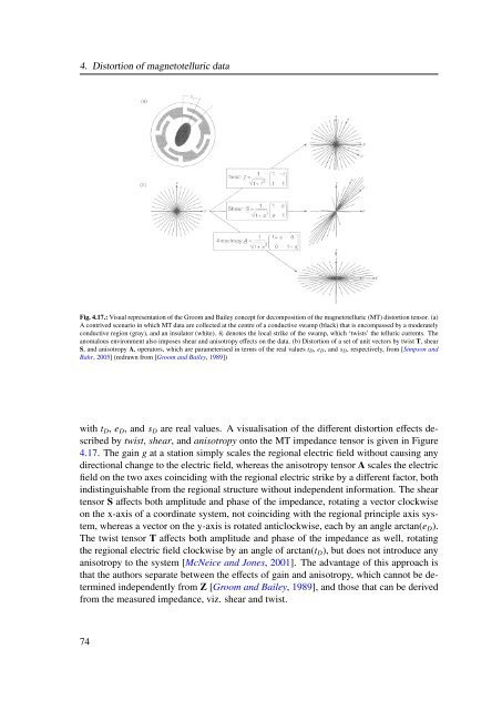
4. Distortion of magnetotelluric data Fig. 4.17.: Visual representation of the Groom and Bailey concept for decomposition of the magnetotelluric (MT) distortion tensor. (a) A contrived scenario in which MT data are collected at the centre of a conductive swamp (black) that is encompassed by a moderately conductive region (gray), and an insulator (white). θt denotes the local strike of the swamp, which ‘twists’ the telluric currents. The anomalous environment also imposes shear and anisotropy effects on the data. (b) Distortion of a set of unit vectors by twist T, shear S, and anisotropy A, operators, which are parameterised in terms of the real values tD, eD, and sD, respectively, from [Simpson and Bahr, 2005] (redrawn from [Groom and Bailey, 1989]) with tD, eD, and sD are real values. A visualisation of the different distortion effects described by twist, shear, and anisotropy onto the MT impedance tensor is given in Figure 4.17. The gain g at a station simply scales the regional electric field without causing any directional change to the electric field, whereas the anisotropy tensor A scales the electric field on the two axes coinciding with the regional electric strike by a different factor, both indistinguishable from the regional structure without independent information. The shear tensor S affects both amplitude and phase of the impedance, rotating a vector clockwise on the x-axis of a coordinate system, not coinciding with the regional principle axis system, whereas a vector on the y-axis is rotated anticlockwise, each by an angle arctan(eD). The twist tensor T affects both amplitude and phase of the impedance as well, rotating the regional electric field clockwise by an angle of arctan(tD), but does not introduce any anisotropy to the system [McNeice and Jones, 2001]. The advantage of this approach is that the authors separate between the effects of gain and anisotropy, which cannot be determined independently from Z [Groom and Bailey, 1989], and those that can be derived from the measured impedance, viz. shear and twist. 74
4.4.5. Caldwell-Bibby-Brown phase tensor 4.4. Removal of distortion effects In the previous approaches aiming to recover the regional geoelectric strike direction in a MT dataset it was assumed that the regional conductivity structure is either 1D or 2D, allowing for a representation of the regional EM field by an impedance tensor with only two non-zero components (cf. Secs. 4.4.1 - 4.4.4). In order to deal with situations where both, local and regional conductivity structures are 3D, Caldwell et al. [2004] introduced the magnetotelluric phase tensor (often simply referred to as phase tensor), utilising the circumstance that the phase relationship between (horizontal) magnetic and electric field vectors is unaffected by galvanic distortion; see Section 4.1 for more information on distortion types. Since horizontal magnetic field components are usually not significantly affected by distortion and respective effects are almost entirely confined to the electric field, horizontal components of the observed magnetic field are assumed to represent the undisturbed regional magnetic field [Caldwell et al., 2004]. With the assumptions that the distortion is only of galvanic nature and that the regional electric field does not vary significantly over the lateral extent of the conductivity heterogeneity, the observed horizontal electric field E D h can be represented as the product of a distortion matrix DΦ and the regional electric field Eh, i.e. E D = DΦ Eh, (4.54) in which the distortion matrix is a second rank, real, 2D tensor . (4.55) DΦ = d11 d12 d21 d22 This assumption implies that the observed field is a linear superposition of the regional electric field and a secondary field, caused by the interaction of the regional field with a local heterogeneity that is in-phase with the regional field. With the additional assumption that only galvanic distortion is present in the data, the relationship between the distorted impedance Z D and the regional impedance Z can be written as Z D = DΦZ. (4.56) Separating the impedance tensors into their real (X) and imaginary (Y) parts, i.e. and Z D = X D + ıY D (4.57) Z = X + ıY, (4.58) yields individual relations for the real and imaginary parts of the distorted and regional matrix, i.e. X D = DΦX (4.59) 75
- Page 60 and 61: 2. Sources for magnetotelluric reco
- Page 62 and 63: 2. Sources for magnetotelluric reco
- Page 64 and 65: 2. Sources for magnetotelluric reco
- Page 67 and 68: Mathematical description of electro
- Page 69 and 70: yields 3.2. Deriving magnetotelluri
- Page 71 and 72: 3.2. Deriving magnetotelluric param
- Page 73 and 74: 3.3. Magnetotelluric induction area
- Page 75 and 76: Depth d s d 1 d 2 d n-2 d n-1 t 1 t
- Page 77 and 78: 3.4. Boundary conditions materials
- Page 79 and 80: 3.5. The influence of electric perm
- Page 81 and 82: 3.5. The influence of electric perm
- Page 83 and 84: 3.5. The influence of electric perm
- Page 85 and 86: Distortion of magnetotelluric data
- Page 87 and 88: 4.1. Types of distortion Fig. 4.1.:
- Page 89 and 90: 4.1. Types of distortion Fig. 4.3.:
- Page 91 and 92: J s 0 s 0 4.1. Types of distortion
- Page 93 and 94: 4.1. Types of distortion Fig. 4.7.:
- Page 95 and 96: Scale Type Terminology Example Atom
- Page 97 and 98: 4.1. Types of distortion the use of
- Page 99 and 100: 4.2. Dimensionality Fig. 4.12.: The
- Page 101 and 102: 1D 2D local 3D/1D 3D/2D regional 4.
- Page 103 and 104: 4.3. General mathematical represent
- Page 105 and 106: 4.4. Removal of distortion effects
- Page 107 and 108: Parameter Geoelectrical application
- Page 109: 4.4. Removal of distortion effects
- Page 113 and 114: 4.4. Removal of distortion effects
- Page 115: Method Applicability Swift angle 2D
- Page 118 and 119: 5. Earth’s properties observable
- Page 120 and 121: 5. Earth’s properties observable
- Page 122 and 123: 5. Earth’s properties observable
- Page 124 and 125: 5. Earth’s properties observable
- Page 126 and 127: 5. Earth’s properties observable
- Page 128 and 129: 5. Earth’s properties observable
- Page 130 and 131: 5. Earth’s properties observable
- Page 132 and 133: 5. Earth’s properties observable
- Page 134 and 135: 5. Earth’s properties observable
- Page 136 and 137: 5. Earth’s properties observable
- Page 138 and 139: 5. Earth’s properties observable
- Page 140 and 141: 5. Earth’s properties observable
- Page 142 and 143: 6. Using magnetotellurics to gain i
- Page 144 and 145: 6. Using magnetotellurics to gain i
- Page 146 and 147: 6. Using magnetotellurics to gain i
- Page 148 and 149: 6. Using magnetotellurics to gain i
- Page 150 and 151: 6. Using magnetotellurics to gain i
- Page 152 and 153: 6. Using magnetotellurics to gain i
- Page 154 and 155: 6. Using magnetotellurics to gain i
- Page 156 and 157: 6. Using magnetotellurics to gain i
- Page 158 and 159: 6. Using magnetotellurics to gain i
4. Distortion of magnetotelluric data<br />
Fig. 4.17.: Visual representation of the Groom and Bailey concept for decomposition of the magnetotelluric (MT) distortion tensor. (a)<br />
A contrived scenario in which MT data are collected at the centre of a conductive swamp (black) that is encompassed by a moderately<br />
conductive region (gray), and an insulator (white). θt denotes the local strike of the swamp, which ‘twists’ the telluric currents. The<br />
anomalous environment also imposes shear and anisotropy effects on the data. (b) Distortion of a set of unit vectors by twist T, shear<br />
S, and anisotropy A, operators, which are parameterised in terms of the real values tD, eD, and sD, respectively, from [Simpson and<br />
Bahr, 2005] (redrawn from [Groom and Bailey, 1989])<br />
with tD, eD, and sD are real values. A visualisation of the different distortion effects described<br />
by twist, shear, and anisotropy onto the MT impedance tensor is given in Figure<br />
4.17. The gain g at a station simply scales the regional electric field without causing any<br />
directional change to the electric field, whereas the anisotropy tensor A scales the electric<br />
field on the two axes coinciding with the regional electric strike by a different factor, both<br />
indistinguishable from the regional structure without independent information. The shear<br />
tensor S affects both amplitude and phase of the impedance, rotating a vector clockwise<br />
on the x-axis of a coordinate system, not coinciding with the regional principle axis system,<br />
whereas a vector on the y-axis is rotated anticlockwise, each by an angle arctan(eD).<br />
The twist tensor T affects both amplitude and phase of the impedance as well, rotating<br />
the regional electric field clockwise by an angle of arctan(tD), but does not introduce any<br />
anisotropy to the system [McNeice and Jones, 2001]. The advantage of this approach is<br />
that the authors separate between the effects of gain and anisotropy, which cannot be determined<br />
independently from Z [Groom and Bailey, 1989], and those that can be derived<br />
from the measured impedance, viz. shear and twist.<br />
74


