approval issue - Canteach
approval issue - Canteach
approval issue - Canteach

You also want an ePaper? Increase the reach of your titles
YUMPU automatically turns print PDFs into web optimized ePapers that Google loves.
Course 234 - Turbine and Auxiliaries - Module Three APPROVAL ISSUE<br />
NOTES & REFERENCES<br />
Page 4<br />
INTRODUCTION<br />
INSTRUCTIONAL TEXT<br />
In the previous turbine courses, you learned about the structure of the main<br />
steam system used in CANDU stations. You also familiarized yourself with<br />
the major components of this system and their functions. Based on this<br />
general knowledge. this module discusses the following operational aspects:<br />
- Assorted operational problems in the main steam system;<br />
- Some operational problems associated with boiler safety valves;<br />
- Boiler pressure control;<br />
- Turbine steam flow control during turbine runup and power maneuvers;<br />
- Action of turbine steam valves in response to typical unit upsets;<br />
- Steam valve testing.<br />
For easy reference, a simplified pullout diagram showing a typical arrangement<br />
of the major steam valves in CANDU stations is attached at the end of<br />
the module. Included with the diagram is a glossary of different names<br />
used for these valves at different stations. The ftrst name listed for each<br />
valve is preferred in these course notes.<br />
The tenn turbine steam valves - frequently used in these notes - encompasses<br />
the following valves: ESVs, GVs, IVs, RESVs. RVs and the extraction<br />
steam check valves.<br />
ASSORTED OPERATIONAL PROBLEMS IN THE<br />
MAIN STEAM SYSTEM<br />
Serious operational problems, possibly leading to severe equipment damage,<br />
can occur in the main steam system if improper operating practices are<br />
used. In this section, the following operational problems are discussed:<br />
- Thermal stresses;<br />
- Pipeline vibration;<br />
- Steam wetness at the turbine inlet;<br />
- Water hammer;<br />
- Steam hammer.<br />
We will examine each of these problems and leam the proper general operating<br />
practices that are used to prevent or at least minimize it. Note that all<br />
these problems. except for the third one, can also occur in auxiliary steam<br />
systems such as the reheat system or the steam reject system.
APPROVAL ISSUE<br />
Steam wetness at the turbine inlet<br />
Course 234 - Turbine and Auxiliaries - Module Three<br />
You will recall that during Donnal operating conditions. the typical boilers<br />
used in CANDU stations produce nearly saturated steam. This significantly<br />
helps in maintaining a very low moisture content of the HP turbine inlet<br />
steam. However, before the boiler steam can enter the turbine. it must flow<br />
through the long pipelines of the main steam system. During this flnw, the<br />
stearn loses heat. As a result, some steam condenses. If not removed,<br />
the cnndensate fnrmed would result in increased wetness' of the turbine<br />
steam. In the extreme case, slugs of water could be formed in the lowest<br />
points nf the system. Driven by the steam flow, they could cause water<br />
hammer in the steam system and possibly water inductinn to the HP turbine,<br />
either of which could inflict severe damage. While this extreme case is described<br />
in the next section of this module. the following covers the less<br />
drastic case.<br />
To ensure a satisfactory dryness.of the HP turbine inlet steam during all operating<br />
conditions, the boilers produce very dry steam, and the main steam<br />
system is well insulated and has several steam traps and drain valves. The<br />
drains and traps are located in the lowest places in the system where the<br />
steam condensate tends to accumulate. Operation of this drainage equipment<br />
is complicated by the fact that the rate of steam condensation In<br />
the system varies widely, depending on the piping temperature. The condensation<br />
process is particularly intenslve during cold startup when the<br />
piping is initially cold. In addition, whenever the steam flow is very small,<br />
it is easy for the condensate to collect in the lowest points of the piping.<br />
Note that a large steam flow makes it more difficnlt as the fast moving steam<br />
picks up droplets from the condensate surface.<br />
Malfunction ,or improper use of the drainage equipment can result either in<br />
increased wetness of the steam supplied to the turbine or an undue loss of<br />
hot steam through the drain lines. To avoid these problems, the following<br />
general operating practices are used:<br />
1. The operation of the steam traps should be periodically monitored<br />
during field Inspections.<br />
This is usually achieved by checking, with a temperature sensor, the<br />
drain pipe temperature upstream and downstream nf each trap. Ifthe<br />
trap operates properly, its upstream pipe sbould be hot and the downstream<br />
pipe should be mach cooler. A cool pipe upstream indicates the<br />
trap failed closed as the water that has accumulated in the pipe keeps it<br />
abnormally cool. Conversely, a hot downstream pipe is indicative of<br />
the trap failed open because the hot sleam blowing through the trap<br />
causes the pipe to be abnormally hOl<br />
NOTES & REFERENCES<br />
• Its adverse coosequeoces<br />
were already discussed in<br />
module 234·1.<br />
¢'> Obi. 3.1 c)<br />
Page 7
APPROVAL ISSUE<br />
Course 234 - Turbine and Auxiliaries - Module Three<br />
another and may reach up to I hour. Needless to say, the original cause<br />
of the boiler level excursion must be rectified before the turbine can be<br />
restarted.<br />
Though both these operating practices seem to be quite obvious and easy to<br />
carry out. their improper execution or even omission has caused several cases<br />
of severe water hammer and water induction accidents in many power<br />
generating stations in the world, including CANDU units.<br />
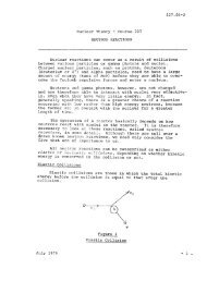
Steam hammer<br />
In the main steam system, steam hammer am occur in the drain lines if<br />
enough condensate has accumulated there and the pressure Is rap<br />
Idly reduced, causing some water to nash to steam. The flashing<br />
process resembles an explosion because it is very fast. and the stearn volume<br />
can be hundreds or even thousands of times as large as the volume of<br />
the water that has flashed. The high pressure waves (surges) that result<br />
propagate through the system, causing other steam pockets to collapse.<br />
This, in turn, generates low pressure waves which travel throngh the system,<br />
causing some water to flash back to steam. The process of intennittent<br />
creation and collapse of steam pockets lasts until the energy ofthe pressure<br />
waves has dissipated, mainly due to friction. In the meantime, the pressure<br />
surges can damage equipment - much like water hammer.<br />
Steam hammer am be prevented by proper operation of the draln<br />
valves as follows:<br />
1. To prevent accumulation of condensate in the piping, the drain valves<br />
should be opened early enough during unit startup and unit unloading.<br />
Ifthere is hardly any water in the piping upstream of the valves, not<br />
much flashing to stearn can occur. Hence, stearn hammer is prevented.<br />
2. Ifa drain valve is found failed in the closed position (eg. due to actuator<br />
or control logic failure), it should be. opened very slowly.<br />
In this case, some condensate is likely to have accumulated upstream of<br />
the failed valve. By opening the vaive slowly, the initial low pressure<br />
surge that can start steam hammer is avoided, and this is why this operating<br />
practice can be effective in steam hammer prevention.<br />
Typically, drain valves are motorized and operated remotely from the control<br />
room. If the controls/actuator fail, manual operation should be carried<br />
out with the above considerations in mind ifstearn hammer is to be avoided.<br />
The same applies to the drain valves used in other systems, ego the extraction<br />
steam system.<br />
NOTES & REFERENCES·<br />
¢'> Db}. 3.2b)<br />
Page 9
APPROVAL ISSUE<br />
Course 234 _ Turbine and Auxiliaries - Module Three<br />
To perform this function adequately. the valves must meet certain legal requirements.<br />
One of them defines the minimum flow capacity of the valves.<br />
This requirement stipulates that the safety valves must be able to remove<br />
safely (ie. without the steam pressure rising excessively) the<br />
steam Dow equivalent to the highest reactor power within the trip<br />
envelope. The statement within the trip envelope accounts for a possible<br />
reactor power transient above the power setpoint. Such a transient can occur<br />
during certain upsets (eg. a loss of reactor regulation) leading to a reactor<br />
trip. Therefore. in order to provide adequate overpressure protection<br />
during unit operation at foil power. the boiler safety valves must actually be<br />
able to discharge more than 100%' of the full power steam flow.<br />
In most stations, the installed flow capacity of all the bniler safety valves<br />
more than meets this requirement The extra flow capacity makes it possible<br />
to remove from service a certain number of the valves (if they leak or fail to<br />
reseat) and still be able to continoe safe operation at full power.<br />
However, if too many valves are unavallahlelor service*• the maximum<br />
boiler steam flow must be reduced such that the remaining operable<br />
safety valves can still remove it safely. This is achieved by the following<br />
actions:<br />
1. TIte reactor trip setpoint (typically. the high neutron power trip)<br />
must he reduced to limit the maximum steaming rate within the trip envelope;<br />
2. The actual reactor power must be decreased if the above action<br />
could result in too small a margin to trip.<br />
In fact, to prevent a reactor trip, it may be necessary to reduce reactor power<br />
first, and then the trip serpoint. Regardless of their sequence, both these actions<br />
ensure that the flow capacity of the available safety valves will be sufficient<br />
to accommodate a possible reactor power transient prior to a high<br />
neutron power trip.<br />
In the stations where the boiler safety valves are also used for crash cooldown,<br />
additional requirements defIne the minimum number of valves that<br />
must be available. This number is smaller than the Dumber of the safety<br />
valves required for adequate overpressure protection while operating at high<br />
power. Details are left for the station specific training.<br />
Improper setting of the lifting pressure setpoint<br />
In order to minimize the probability of safety valve malfunction, its lifting<br />
pressure and blowdown must be properly adjusted. Let us now examine<br />
the adverse consequences and operating concerns caused by improper<br />
seuing of the lifting pressure of a boiler safety valve:<br />
NOTES & REFERENCES<br />
• Usually, 115-120%.<br />
Obj. 3.3 a)<br />
• The limit on tbe number<br />
of unavailable valves depends<br />
on tbe station. In<br />
the extreme case, all<br />
boiler safety valves must<br />
be available to allow full<br />
power operation.<br />
Obj. 3.3 b)<br />
Page II
APPROVAL ISSUE<br />
BOILER PRESSURE CONTROL<br />
Course 234 - Turbine and Auxiliaries· Module Three<br />
Boiler performance - so vital to operation of the whole unit - strongly depends<br />
on effective control of boiler pressure. In this module, the following<br />
aspects of boiler pressure control are addressed:<br />
- Causes of boiler pressure changes;<br />
- Normal boiler pressure control;<br />
- Automatic responses to boiler pressure upsets;<br />
- Operation of the s!!lam reject valves.<br />
Causes of boiler pressure changes<br />
You will recall that the primary function of the boilers is to transfer heat<br />
from the reactor coolant to the boiler water. The produced steam then removes<br />
heat from the boilers as it flows Oul<br />
For overall unit control, It Is very Important to match the heat supply<br />
to the boDers with the heat removal from them. When the two balance<br />
each other. the energy stored in the boiler water and steam does not<br />
change. Consequently, boiler pressure and temperatore stay constant.<br />
If the heat input to the boiler exceeds the heai output, the surplus<br />
heat is being deposited in the boilers, thereby raising its pressure and temperature.<br />
The opposite happens when the heat inpnt is below the heat output<br />
- in this case, some heat is being withdrawn from the boilers causing<br />
the boiler pressure and temperature to drop. These cases are summarized in<br />
the table below.<br />
CASE<br />
Heat input = Heat output<br />
Heat input > Heat output<br />
Heat input < Heat output<br />
EFFECT<br />
p, T stay conslant<br />
p, T rise<br />
p, T drop<br />
FIg. 3.1. The effect of boiler heat flow balance on boiler pressure (p)<br />
and temperature (T).<br />
During transition periods, boDer pressure measurements change faster<br />
than temperature measurements. Therefore. to control the heat flow<br />
through the boilers, we monitor boiler pressure, and not boiler temperature.<br />
NOTES & REFERENCES<br />
Page 15
Course 234 - Turbine and Auxiliaries - Module Three APPROVAL ISSUE<br />
NOTES & REFERENCES<br />
... Recall from module 234-1<br />
that in the turbine, steam<br />
pressure is approximately<br />
proportional to load, and<br />
thus, the steam flow.<br />
Page 18<br />
point to the reactor regulating system. The system then brings re<br />
-actor power to the new setpoint. Along with the boiler pressure error,<br />
the rate at which the turbine steatO flow (and hence, the boiler heat output)<br />
is changing is monitored, too. This is achieved by measuring the<br />
steam pressure at the HP turbine inlet or close to it*. This extra input allows<br />
the BPe to anticipate an upcoming change in boiler pressure and<br />
respond to it in advance. thereby minimizing pressure fluctuations.<br />
This is the preferred mode of BPe operatiun in mostCANDU stations.<br />
Its natOes refleet the fact that when this mode ofcontrol is used, changes<br />
in the reactor power lag behind changes in the turbine generator output.<br />
2. The reactor leading mode (also called the turbine following mode).<br />
In this mode, changes in reactor power occur before changes in the boiler<br />
steatO flow. Reactor power is controlled independently, and boiler<br />
pressure is controlled by adjusting the setpoint to the turbine<br />
governing system. This causes the turbine steatO valves to change the<br />
boiler steatO flow as requested by the BPe. Needless to say, it causes<br />
the generator output to change accordingly.<br />
To enhance boiler pressure control when the BPe operates in this mode,<br />
some other parameters (in addition to the boiler pressure error) are used<br />
as inputs by the BPe. These typically include the rate at which boiler<br />
pressure is changing and the rate at which reactor power is changing.<br />
Their use allows the BPe to anticipate the upcoming changes in boiler<br />
pressure, and hence minimize pressure transients.<br />
This is the preferred mode of BPe operation in some CANDU stations.<br />
But in most stations, this is the alternate mode which is selected when<br />
the preferred reactor lagging modO ofoperation is not suitable. For exatOp!e,<br />
this happens following a reactor trip, stepback or setback when<br />
the reactor power is either lost or cannot be manoeuvred due to some<br />
operational problem.<br />
SUMMARY OF THE KEY CONCEPTS<br />
• BPC controls boiler pressure at its setpoint. It also changes the setpoint<br />
during some operating states.<br />
• Boiler pressure rises during warmup of the HT system and the boilers.<br />
A temporary rise in boiler pressure occurs on a turbine trip or a load rejection.<br />
A smaller transient pressure increase is caused by unit unloading<br />
in the reactor lagging mode or unit loading in the reactor leading<br />
mode. But in the stations where boiler pressure setpoint is ratOped<br />
down with ffi!ing reactor power, unit loading causes boiler pressure to<br />
decrease. and unit unloading to rise.
Course 234 - Turbine aDd Auxiliaries· Module Three APPROVAL ISSUE.<br />
NOTES & REFERENCES<br />
Page 22<br />
demand. Any surplus boiler steam is then handled by the SRVs. This<br />
greatly simplifies the startup. because the requirements and limitations<br />
imposed on the nuclear side can be satisfied without affecting those<br />
present in the conventional side and vice versa.<br />
The same approach is often used while warming up the HT system and<br />
the boilers. The reactor power is then kept somewhat above that required<br />
to bring about the selected heatop rate and the surplus heat is rejected<br />
by the SRVs.<br />
Nonnally, a certain pressure error must be present (as shown in Fig. 3.2)<br />
for these valves to start opening. But there are a few exceptions. For example,<br />
during poison prevent operation this error offset is eliminated such<br />
that the valves can control the boiler pressure right at its serpoint. Also,<br />
upon a turbine trip or load rejection, BPC opens these valves without waiting<br />
for any pressure error. This fast action minimizes the resultant pressure<br />
transient considerably.<br />
Types of SRVs<br />
The SRVs used in any CANDU unit are of two different sizes. The smaller<br />
valves have a combined capacity of about 5-10% of the full power steam<br />
flow. They are used during unit startup and to handle minor pressure transients,<br />
whereas more serious transients are accommodated by the larger<br />
SRVs.<br />
Depending on the station, the large SRVs discharge steam to either<br />
atmosphere or the turbine condenser - the latter being the more typical<br />
arrangement. In the stations where these valves exhaust to atmosphere,<br />
they can handle essentially the whole full power steam flow. This large<br />
flow capacity stems from the possible use of these valves for crash cooling.<br />
During poison prevent operation. however, these valves normally handle<br />
only about 65-70% of the full power flow, with the reactor power reduced<br />
appropriately. This minimizes consumption of makeup water, while keeping<br />
reactor power high enough to prevent poisoning.<br />
In the other stations, where the large valves exhaust to the condenser, they<br />
are commonly referred to as CSDVs which stands for condenser steam dis- .<br />
charge (or dump) valves. Their combined capacity is usually limited to<br />
about 65-70% of the full power steam flow in order to prevent overloading<br />
of the condenser. This limit reflects the fact that compared with the turbine<br />
exhaust steam, each kilogram of the steam rejected by these valves possesses<br />
more heat because it has not lost any in the turbine. Because of this limit,<br />
full reactor power cannot be maintained when these valves operate. On the<br />
other hand, the limit is high enough to allow for successful poison prevent<br />
operation.<br />
In all CANDU stations, lhe smaller SRVs exhaust to atmosphere.<br />
In the stations equipped with CSDVs, the smaller valves are called ASDVs
Course 234 - Turbine and Auxiliaries - Module Three APPROVAL ISSUE<br />
NOTES & REFERENCES<br />
'" Above 1650-1750 rpm.<br />
depending on the station.<br />
Page 26<br />
also the emergency stop valves and intercept valves). Operation of the remaining<br />
turbine steam valves (ie. the reheat emergency stop valves and release<br />
valves) is not affeCled.<br />
The arrangement of the turbine steam valves is shown in the pullout diagram<br />
at the module end. Nole that sleam is supplied to the HP turbine by four<br />
pipelines in parallel. In each line, one governor valve (GV) and one emergeoey<br />
stop valve (ESV) are installed. Each LP turbine is supplied with<br />
stearn via two lines in parallel, each equipped with one inlercept valve (N)<br />
and, in most stations, one reheat emergency stop valve (RESV).<br />
After this general introduction, let us now discuss each type of governing in<br />
more detail.<br />
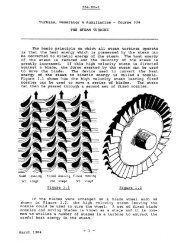
The principle of throttle governing is very simple: the whole flow of turbine<br />
slearn is throttled (hence, the name of this governing). The throttling is<br />
identical in all the steam pipelines that are in parallel. Therefore, the valves<br />
that are controlling (throttling) the slearn flow operate in unison: at any<br />
given moment, their openings are - in principle -identical. As a result,<br />
the pressure and lemperature of the slearn supplied via one pipeline do not<br />
differ from those in the other lines. Therefore, the individual sleam flows<br />
are allowed to mix before they enler the turbine fmt stage.. The mixing occurs<br />
inside the turbine casing, in the annulus chamber to which the steam<br />
admiSsion pipes are connected. Consequently, at any steam flow rate (even<br />
when it is very small), all the nozzles in the ftrst stage are supplied with<br />
steam. Since steam is admitted all around the turbine inlet are, this method<br />
of governing is also called full arc admission.<br />
Throttle governing is used in most CANDU stations. Between these stations,<br />
there are some differences regarding the slearn valves that are involved<br />
in the governing. This is caused by turbine design differences in<br />
these stations (different turbine manufacturers and/or the age of the design).<br />
Two lDl\lor variations of this method of governing are as follows:<br />
I. In some stations, it is performed soleiy by the governor valves<br />
(GVs). They control the slearn flow over the whole range of turbine<br />
speed (during runup) and load.<br />
2. In other stations, the GVs control the steam Dow only when the<br />
turbine speed is close to the synchronous speed"'. This occurs<br />
during the ftnal stage of turbine runup, not to mention the normal operation.<br />
During the initial phase of runup, the GVs stay fully open,<br />
and the steam now is controlled by the emergency stop valves<br />
(ESVs).<br />
Note that accurate control of a small steam flow by valves that are sized for<br />
the full power flow is difftcult To improve it, three methods are used.<br />
First, In some stations, only two out of four GVs or ESVs are used during<br />
runup, while the other two valves remain closed.
APPROVAL ISSUE<br />
Course 234 - Turbine and Auxiliaries - Module Three<br />
Second, each valve that controls the small steam flow usually has a pilot<br />
valve (ie. a smaller disc placed inside the main disc) which throttles the<br />
steam flow while the main disc remains shut.<br />
Third, in some stations, the Intercept valves (IVs) assist the GVs in<br />
controlling the small steam Dow that occurs during turbine runup and<br />
operation at light loads. Instead of being performed solely by the GVs,<br />
throttling is now dIstributed between them and the N s. Therefore, for any<br />
given steam flow, the opening of the GVs is increased as compared with the<br />
situation when the Ns stay fully open. As a result, the accuracy of controlling<br />
the small steam flow is improved. Note that throttling of the IVs is<br />
used only when the steam flow is small. At medium and high turbine power,<br />
these valves stay fully open.<br />
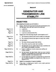
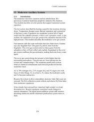
The principle of nozzle governing is to adjust the number of the turbine<br />
rust stage nozzles that the steam is allowed to flow through. To achieve<br />
this, the nozzles are divided into a few groups (typically four). Each group<br />
of the nozzles is isolated from the others and supplied via its own pipeline<br />
with a GV as shown in Fig. 3.3 below.<br />
GV1 GVa<br />
Fig. 3.3. Nozzle governing· the arrangement of the turbine first stage<br />
nozzle. end the governor valv.. (OVa).<br />
In this method of governing, the ESVs are not used for flow control. In<br />
CANDU units that employ this governing, the IVs are not used for flow<br />
control either. It is performed solely by the GVs which operate, in principle,<br />
sequenUalIy. At very small steam flow rates, only GVl is controlling,<br />
while the other GVs are closed. When GVl is fully open and the<br />
steam demand increases further, GV2 starts opening. This contioues until<br />
all the GVs are fully open. Note that over a large range of partialloada one<br />
NOTES & REFERENCES<br />
Page 27
Course 234 - Turbine and Auxiliaries· Module Three APPROVAL ISSUE<br />
NOTES & REFERENCES<br />
Page. 48-49 <br />
Page 28<br />
or more of the GVs are closed, thereby isolating some nozzles in the first<br />
stage. This is why this method of governing is also known as partial arc<br />
admission (steam only enters on a portion of the turbine inlet arc).<br />
The above description of valve operation is simplified and only illustrates<br />
the principle ofnozzle governing. The actual valve operation is somewhat<br />
different to minimize some operational problems. Since this method of governing<br />
is used only in a few CANDU units. details are left for the station<br />
specific training.<br />
For clarity. it must be stated that in this methud of turbine governing. turbine<br />
nozzies are divided into groups only in the Orst turbine. stage. You<br />
realize that once the steam has left the individual groups of nozzles. its pressure<br />
equalizes. This is because all the nozzle groups exhaust into the same<br />
common area (where the moving blades spin around). Since the inlet pressure<br />
to all the nozzles In the second stage (let alone. the other stages downstream)<br />
is equal, their separations into individual groups would make no<br />
sense.<br />
SUMMARY OF THE KEY CONCEPTS<br />
• Varying the turbine steam flow during turbine runup changes the turbine<br />
speed, while the generator load remains zero.<br />
• When the generator is connected to a large grid. varying the turbine<br />
steam flow affects the generator output and the speed remains approximately<br />
constant<br />
• In throttle governing, the turbine steam valves operate in unison, and the<br />
turbine frrst stage nozzles are not divided into separate groups.<br />
• During turbine runup. throlde governing is performed by different<br />
valves, depending on the station. In some stations, the GVs are used<br />
over the whole speed range. In other stations. the avs control the flow<br />
only when turbine speed is close to 100%. In those stations. the ESVs<br />
control the stearn flow (with the avs fully open) at lower turbine<br />
speeds.<br />
• In some stations. the IVs assist the avs in throttling the very small<br />
steam flow that occurs during turbine runup and at light loads. This improves<br />
the accuracy of flow control.<br />
• In all stations. turbine load is controlled by the avs.<br />
• In nozzie governing. the turbine first stage nozzles are divided into a few<br />
groups. each of them having its own steam supply line. In principle. the<br />
avs operate sequentialIy. The ESVs and the IVs are not used for flow<br />
control.<br />
You can now do assignment quesdons 19-21.
APPROVAL ISSUE<br />
ACTION OF MAJOR TURBINE STEAM VALVES<br />
IN RESPONSE TO TYPICAL UNIT UPSETS<br />
Course 234 - Turbine and Auxiliaries - Module Three<br />
Proper operation of the turbine steam valves in response to various unit upsets<br />
is vital because equipment safety - and sometimes personnel safety as<br />
well- depend on it. Therefore, it is very important that yon know how and<br />
why these valves operate during these emergency conditions. In this section,<br />
you wi111earn about action of the turbine steam valves in response to<br />
the following upsets:<br />
- Reactor trip;<br />
- Turbine trip;<br />
- Load rejection.<br />
The last two terms are described in more detail. For the turbine trip, you<br />
will learn about its general purpose, typical causes and two major types. As<br />
for the load rejection, you will find out how it differs from a turbine trip,<br />
and how and why turbine speed varies.<br />
REACTOR TRIP<br />
Required response regarding the turbine steam flow<br />
On a reactor trip, and particularly when from a high power level, the heat input<br />
to the unit is drastically decreased. In response, the GV. close gradually'<br />
to reduce the turbine steam Dow in an attempt to match the reduction<br />
in the heat input.<br />
Failure to do this wouid result in very fast cooling ofthe boilers and the heat<br />
transport (HT) system. The reason is that much more heat would be removed<br />
with boiler steam than would be supplied by the reactor and HT<br />
pumps. Due to the cooling, the boiler temperature (thus, pressure) and the<br />
coolant temperature would drop rapidly. The resultant coolant shrink<br />
would be so fast and so large that the HT pressurizing system could not prevent<br />
the coolant pressure from dropping.<br />
Note that with dropping boiler pressure, the turbine steam flow would be<br />
decreasing, thereby reducing the rate of heat removal from the boilers and<br />
the HT system. After several minutes, a new thermal equilibrium would be<br />
reached where the boiler temperature/pressure and the coolant temperature<br />
would stabilize at a low level, and the HT pressurizing system would restore<br />
the normal coolant pressure.<br />
Nonetheless, the transient fast drop in the boiler steam and reactor coolant<br />
temperature and pressure causes the following operating concerns:<br />
1. Excessively low HT pressure could result in some of the reactor<br />
coolant flashing to steam. The presence of large quantities of vapour in<br />
the coolant could have the following adverse consequences:<br />
NOTES & REFERENCES<br />
Obj. 3.6 a)<br />
• The valve action is described<br />
in more detail on<br />
the next page.<br />
Page 29
Course 234 - Turbine aod Auxiliaries· Module Three APPROVAL ISSUE<br />
NOTES & REFERENCES<br />
'" Recall that during a se·<br />
quential trip, the genera·<br />
tor circuit breakers open<br />
only wben it is confumed<br />
that the turbine steam<br />
flow bas been stopped.<br />
Page 34<br />
In addition to the above, release valves (RVs), or their equivalents as<br />
outlined below, open quickly to release to the condenser the steam trapped<br />
inside the turbine set between the closed GVs and Ns. Note that, due to<br />
lack of a net flow, the pressure of the trapped steam tends to equalize. As a<br />
result, the HP turbine exhaust pressure can rise above its nonnal full power<br />
level. This could be particularly bad if a malfunction caused some GVsI<br />
ESVs to close slower than the NslRESVs. Opening or the RVs tberefore<br />
prevents the following problems:<br />
a) Possible overpressure of the moisture separators, reheaters. the exhaust<br />
part of the lIP turbine, and interconnecting pipelines;<br />
b) Increased driving torque produced by the LP turbines due to failure<br />
of some N(s) to close. This would result in increased overspeed on a<br />
nonsequential trip. And during a sequential trip, the generator disconnecting<br />
from the grid would be delayed·. In both cases, chances for<br />
equipment damage would be increased. This concern applies particularly<br />
to the Jew CANDU units that have no RESVs, because their absence<br />
increases greatly the risk of a flow path to the LP turbines being left<br />
open during a turbine trip,<br />
There are many differences in the RVs used in different stations. The largest<br />
flow capacity RVs are installed in the few units that have no RESVs.<br />
For the steam trapped inside the turbine set, the large RVs create a preferred.<br />
low-resistance flow path to the condenser. thereby decreasing the<br />
amount of the steam that would drive the LP turbines due to IV failure.<br />
Newer CANDU stations are equipped with RESVs in series with the IVs<br />
which greatly increases the reliability of stopping the steam flow to the LP<br />
turbines. Therefore, large RVs are not necessary, and either only small<br />
RVs or no RVs at all are installed. In the latter case, some other valves (eg.<br />
moisture separator drains dump valves), whose primary function is quite<br />
different, open upon a turbine trip to release the trapped steam. For better<br />
overpressure protection, the RVs or their equivalents are backed up by<br />
bursting discs or safety valves.<br />
. The speed at which the turbine steam valves operate Is very impor.<br />
tant in ensuring effective protection of the equipment when an operational<br />
problem calls for a turbine trip. Nonnally, these valves need about 0.5 seconds<br />
to reach their safe position.<br />
SUMMARY OF THE KEY CONCEPTS<br />
• On a reactor trip, the turbine steam flow is gredually reduced by the<br />
GVs (assisted by the IVs, in some stations). This action prevents an excessive<br />
drop in the HT system pressure, and a fast drop in the boiler<br />
stearn and reactor coolant temperatures with all their adverse consequences.
APPROVAL ISSUE<br />
Course 234 - Turbine and Auxiliaries - Module Three<br />
• The main purpose of a turbine trip is to prevent/minimize damage to the<br />
equipment which could likely happen if operation were continoed.<br />
• Doring a seqoential torbine trip, the torbine steam flow is stopped first,<br />
and then the generator circuit breakers open. This prevents a turbine<br />
overspeed and is the reason why sequential trips are preferred.<br />
• During a nonsequential turbine trip, the generator circuit breakers open<br />
.concorrently with or prior to the action of the turbine steam valves to<br />
stop the steam flow. Some overspeed is unavoidable. Two major operating<br />
events that result in a nonseqoential torbine trip are an excessive<br />
turbine overspeed and various electrical faults in·the generator or its electrical<br />
auxiliaries.<br />
• Upon a turbine trip, most of the turbine steam valves close quickly to<br />
stop steam supply to the torbine. The only exceptions are the release<br />
valves or their equivalents that open to release the steam trapped inside<br />
the turbine set between the closed GVs and IVs.<br />
LOAD REJECTION<br />
Differences in comparison with a turbine trip<br />
A load rejection refers to an operational upset when the generator is<br />
quickly disconnected from the grid in response to some acute grid<br />
problem, ego due to a lighuting strike. The two major differences between<br />
a load rejection and a turbine trip:<br />
I. It is the grid, and not the unit, that is having a problem.<br />
Therefore, there is no need for a turbine rundown. On the contrary. it<br />
would postpone and complicate resynchronization with the grid (once<br />
the grid problem has been cleared) because the turbine generator speed<br />
would have to be raised frrst.<br />
2. Although disconnected from the grid, the generator is stili supplying<br />
the unit service load.<br />
This is done to minimize the risk of a loss of Class IV power. Note that<br />
chances of this upset are increased because disconnection of the generator<br />
from the grid has already disabled one of the soorces of Class N<br />
power.<br />
Turbine speed transient on a load rejection<br />
Immediately after disconnecting the generator from the grid, turbine generator<br />
speed rises rapidly. This happens because a load rejection reduces the<br />
generator countertorque instantaneously (to a level that corresponds to the<br />
unit service load, which is typically 6-7% FP). The resultant surplus of the<br />
turbine driving torque over the reduced generator countertorque causes the<br />
NOTES & REFERENCES<br />
Obj. 3.8 b)<br />
Page 3S
Course 234 - Turbine and Auxiliaries - Module Three APPROVAL ISSUE<br />
NOTES & REFERENCES<br />
... Recall that this is done to<br />
assist the OVs in controlling<br />
the small steam flow<br />
when the generator is supplying<br />
the service load.<br />
Page 38<br />
4. Intercept valves (lVs).<br />
In all stations. at the onset of a load rejection, the IVs close<br />
quickly to stop the steam flow to the LP turbines. Recall that in order to<br />
limit the transient overspeed satisfactorily, the stearn that has passed the<br />
closing avs and is flowing through the HP turbine. moisture separators.<br />
reheaters and interconnecting pipelines must be prevented from entering<br />
the LP turbines.<br />
When the dropping turbine speed approaches 100% and while<br />
the GVs are still fuily closed, the IVs reopen. Their opening may<br />
be full or partial. slow or fast, depending on the station. Typically, they<br />
open only partially·. But in some stations, the Ns open fully to reestablish<br />
the normal flow path through the LP turbines.<br />
The rate at which the IVs reopen also varies from station to station. In<br />
the early CANDU stations, where release valves (RVs) are installed. the<br />
Ns open quickly. By that time. the steam that was trapped inside the<br />
turbine upstream the Ns has been released to the condenser via the<br />
RVs. Therefore, opening of the IVs has no effect on the rate at which<br />
the turbine speed is dropping (see the solid line graph in Fig. 3.4).<br />
In the new CANDU stations, no dedicated RVs are installed. Their<br />
equivalents are of a relatively small sire, and cannot quickly remove the<br />
trapped stearn. Therefore, a significant quantity of this steam is still<br />
present in the turbine, when the Ns start reopening..Ifreleased too<br />
quickly, this stearn would drive the turbine enough to cause it to overspeed<br />
again. To prevent it, the IVs reopen slowly. During this process,<br />
turbine speed remains approximately constant until most of the trapped<br />
steam has been released. Then, turbine speed resumes dropping again<br />
(see the dashed line graph in Fig. 3.4).<br />
5. Release valves (RVs) or their equivalents.<br />
InItially, these valves open quickly to release to the condenser the<br />
steam trapped inside the turbine set between the closed avs and Ns.<br />
This action serves the purposes outlined in the turbine trip section of this<br />
module.<br />
Prompt opening of the RVs also prevents a turbine !tip on HP turbine<br />
exhaust pressure. Avallable in most stations, this !tip should occur before<br />
the pressure reaches a level at which the reheater safety valves or<br />
bursting discs (depending on the station) operate. Note that the generator<br />
cannot be quickly returned to the grid ifsuch a !tip has occurred. instead,<br />
the cause of overpressure would have to be corrected first. This<br />
loss of production can be avoided if the RVs operate properly.<br />
After the IVs have reopened on dropping turbine speed, the<br />
RVs reclose to establish the normal flow path through the LP turbines.<br />
In the stations, where no RVs are installed, their substitutes (eg.
APPROVAL ISSUE<br />
Course 234 - Turbine and Auxiliaries· Module Three<br />
lowed to accumulate excessively. such deposits could slow down the<br />
valve operation to a point that their safety function would be compromised.<br />
promoting a severe accident Note that the valves do not have to<br />
be totally disabled - it is enough if their operation is just sluggish.<br />
Because base load units operate at a steady power level for extended<br />
periods of time. their steam valves and associated hydraulic components<br />
in the turbine governing system remain in essentially the same position.<br />
This creates excellent conditions for buildUp of various deposits.<br />
and has caused numerous valve failures in many stations in the world.<br />
This can be prevented by stroking the valves during their routine onpower<br />
tests to scrape the thin layer of deposits off. Needless to say.<br />
proper purity of the hydraulic fluid and boiler steam must be maintained.<br />
too.<br />
3. To ensure that the unavailability (Q) of the turbine steam valves<br />
(ie. the fraction of time they are unavailable to perform their intended<br />
functions) does not exceed the unavailability target (Qr). ie.<br />
0sQr.<br />
Recall that Q = AT /2<br />
where: A= valve failure rate (failure/year);<br />
T = test intervals (years).<br />
Routine tests allow for verification of the assumed values of the failure<br />
rates (A) for vatious valves. Ifthe actual values are larger than those assumed.<br />
a corrective action (more frequent testing and/or design changes)<br />
can be taken to ensure that 0sQr.<br />
Failure of a valve to pass a test can have a profound effect on the operation<br />
of the unit. In the extreme case, continued operation may not be allowed<br />
and the turbine must be shut down for valve repairs. However, the consequences<br />
vary widely. depending on the station and the type of the failed<br />
valve. The most severe consequences apply to faulty ESVs and GVs. Details<br />
are left for the station specific training.<br />
SUMMARY OF THE KEY CONCEPTS<br />
• Turbine steam valves are tested during turbine startup. following any<br />
maintenance that might have affected the valve performance. and routinely<br />
when the unit is running.<br />
• Routine on-power tests of the turbine steam valves are performed for<br />
three major reasons. First. to discover failed valves before a dangerous<br />
multiple valve failure has achance to develop. Second. an excessive<br />
buildup of deposits on the valve stems and in their hydraulics is prevented<br />
when the valves are stroked. Finally. the assumed valve failure rate<br />
NOTES & REFERENCES<br />
Page 41
APPROVAL ISSUE<br />
ASSIGNMENT<br />
Course 234 - Turbine add Auxiliaries - Module Three<br />
I. a) Large thermal stresses in the steam system occur
Course 234 - Turbine and Auxiliaries - Module Three APPROVAL ISSUE<br />
NOTES & REFERENCES<br />
Page 44<br />
3. a) The rate ofcondensate collection in the stearn system is particu-<br />
laIly high during _<br />
i)<br />
til<br />
because:<br />
b) The usual method ofmonitoring steam trap perfonnance is to<br />
Proper operation of the trap is indicated by _<br />
c) The drain valves in the steam system should be open whenever<br />
d) The reason why steam should not be readntitted to the torbine immediately<br />
following its trip upon a very high boiler level is<br />
4. a) In the steam system, steam hammer can occur when _<br />
b) To prevent steam hammer, the drain valves should be operated as<br />
follows:<br />
1)<br />
This practice achieves its purpose by _
APPROVAL ISSUE<br />
il)<br />
Course 234 - Turbine and Auxiliaries· Module Three<br />
This practice achieves its purpose by _<br />
5. a) To provide adequate overpressure protection during all operating<br />
conditions, the boiler safety valves must be capable of removing<br />
safely the stearn flow equivalent to _<br />
This requirement accounts for _<br />
b) Iftoo many valves are unavailable for overpressure protection,<br />
the fnllnwing actinns must be talcen:<br />
i)<br />
il)<br />
in order to _<br />
in orderto _<br />
6. a) Safety valve blowdown is defined as --,.__<br />
b) Safety valve simmer is defined as _<br />
c) Safety valve chatter is defined as _<br />
7. a) When the lifting pressure of a boiler safety valve is set too high,<br />
the following adverse consequences/operating concerns result:<br />
i)<br />
il)<br />
NOTES & REFERENCES<br />
Page 4.5
Course 234 - Turbine and Auxiliaries· Module Three APPROVAL ISSUE<br />
NOTES & REFERENCES<br />
Page 46<br />
b) When this setting is too low. it causes the following adverse consequences/operating<br />
concerns:<br />
i) Ifno corrective actions were taken: _<br />
ti) Ifthe valve were quickly shimmed or removed from service:<br />
8. a) A blowdown setting of a safety valve that is too high can result in<br />
b) The adverse consequence/operating concern caused bya blowdown<br />
setting of a boiler safety valve that is too low is<br />
9. Loss of hot boiler stearn through a faulty/malfunctioning boiler safety<br />
valve has the following adverse consequences:<br />
a)<br />
b)<br />
c)<br />
d)<br />
10. a) Boiler safety valves are tested routinely in order to _<br />
b) Their testing frequency is determined by the more restrictive of<br />
the following:<br />
i)<br />
ill
APPROVAL ISSUE<br />
II. Major functions of the BPC program are:<br />
a)<br />
b)<br />
Course 234 - TurbiDe acd Auxiliaries - Module Three<br />
12. The BPC program adjusts the boiler pressure setpoint during the following<br />
unit operating states:<br />
a)<br />
b)<br />
13. Under the assumption of a constant boiler pressure setpoint over the<br />
whole reactor power range, boiler pressure changes as follows during<br />
each of the following operating states:<br />
Operating state<br />
Cooling of the boilers and the HI" system<br />
Load rejection<br />
Reactor trip, stepback or setback<br />
Unit loading in the reactor lagging mode<br />
Unit loading in the reactor leading mode<br />
Turbine trip<br />
Unit unloading in the reactor lagging mode<br />
Unit unloading in the reactor leading mode<br />
Warming of the boilers and the Hfsystem<br />
Boiler pressure<br />
(drops I rises)<br />
(drops Irises)<br />
(drops I rises)<br />
(drops Irises)<br />
(drops I rises)<br />
(drops I rises)<br />
(drops I rises)<br />
(drops I rises)<br />
(drops I rises)<br />
14. To maintain boiler pressure at its se!pOint, BPC adjusts the following<br />
parameter:<br />
a)<br />
b)<br />
when the unit operates in the reactor lagging mode.<br />
when the unit operates in the reactor leading mode.<br />
IS. Suppose that aCANDU unit is operating in the reactor leading mode at<br />
full power when the reheat steam is suddenly cut off in response to reheater<br />
problems.<br />
a) Boiier pressure wouid initially (drop I rise) as a result of this upset.<br />
b) BPC would attempt to return boiler pressure to its setpoint by<br />
NOTES & REFERENCES<br />
Page 47
Course 234 - Turbine and Auxiliaries· Module Three APPROVAL ISSUE<br />
NOTES & REFERENCES<br />
Page 48<br />
c) This action may be unsuccessful due to -<br />
In this case, BPC would _<br />
16. Listed in the order of increasing boiler pressure error, the following actions<br />
(other than normal control action of BPC) occur in response to:<br />
a) Too high boiler pressure:<br />
I)<br />
ill<br />
iii)<br />
b) Too low boiler pressure:<br />
i)<br />
ill<br />
iii)<br />
17. In the stations where all the SRVs discharge steam to atmosphere:<br />
a) The duration of poison prevent operation is lintited by<br />
b) Two other operating concerns caused by discharging boiler stearn<br />
to atmosphere are:<br />
i)<br />
ill<br />
18. Two concerns associated with operationof the CSDVs are:<br />
a)<br />
b)<br />
19. The effect of increasing stearn flow on the turbine speed and generator<br />
output is as follows:<br />
a) During runup: _<br />
b) When the generator is connected to a large gtid: _
APPROVAL ISSUE<br />
Course 234 - Turbine and Auxiliaries· Module Three<br />
20. a) In throttle governing. the flfst stage nozzles (are I are not) divided<br />
into individual groups and the GVs operate (in unison I sequentially).<br />
b) In nozzle governing. the fIrSt stage nozzles (are I are not) divided<br />
into individual groups and the GVs operate (in unison I sequentially).<br />
21. The turbine steam flow is controlled by the following valves:<br />
TUIbine Throttle Nozzle<br />
Status Governing Governing<br />
Runup<br />
Synchronized<br />
22. Failure to reduce the turbine steam flow in response to a reactor trip<br />
causes the following adverse consequences/operating concerns:<br />
a) Due to an excessively low HI system pressure:<br />
i)<br />
ti)<br />
b) Due to the fast dropping boiler steam and reactor coolant temperatures:<br />
23. a) On a reactor trip, the steam flow is (gradually I rapidly) reduced<br />
by the valves.<br />
b) In some stations. this action is accompanied by the _<br />
valves which close (fully I partially). The purpose of this is:<br />
c) In addition. the extraction steam check valves (clo.."le I onen).<br />
NOTES & REFERENCES<br />
Page 49
Course 234 - Turbine and Auxiliaries - Module Tbree<br />
NOTES & REFERENCES<br />
Page 50<br />
APPROVAL ISSUE<br />
24. a) The general purpose of a turbioe trip is _<br />
b) A turbioe trip can be caused by operating events such as:<br />
Event Hazard ifooeration continued<br />
25. a) Every turbine trip includes two major actions:<br />
i)<br />
ii)<br />
in order to _<br />
in order to _<br />
b) The difference between sequential and nonsequential turbine trips<br />
is _<br />
c) A sequential turbine trip would not be the correct response to an<br />
electrical fault in the generator or its auxiliaries because
APPROVAL ISSUE<br />
26<br />
Upon a turbine trip. the Olrbine valves operate as follows:<br />
Valves Action Purpose<br />
ESVs<br />
avs<br />
RESVs<br />
Ns<br />
RVs'<br />
Extr.stm.<br />
check<br />
valves<br />
Course 234 - Turbine aDd Auxiliaries - Module Three<br />
27.<br />
The major hazard to the turbine generator represented by a load rejec-<br />
28<br />
tion is<br />
a) The major differences between a load rejection and a Olrbine trip<br />
are:<br />
i)<br />
il)<br />
NOTES & REFERENCES<br />
• Or their equivalents.<br />
Page 51
Course,234 - Turbine and Auxiliaries - Module Three<br />
'OTES & REFERENCES<br />
oil Or their equivalents.<br />
oil Or'tbeir equivalents.<br />
Page 52<br />
APPROVAL ISSUE<br />
b) At the onset of a load rejection, the turbine valves typically operate<br />
as follows:<br />
Valves Action Purpose<br />
aVS .<br />
ESVs<br />
IVs<br />
RESVs<br />
RVs'<br />
Extr.stm.<br />
cbeck<br />
valves<br />
c) When the dropping turbine speed approaches 100%, the turbine<br />
valves typically operate as follows:<br />
Valves Action Purpose<br />
aVS<br />
ESVs<br />
IVs<br />
RESVs<br />
RVs'<br />
Extr.stm.<br />
NRV<br />
actuators
APPROVAL ISSUE<br />
Course 234 - Turbine and Auxiliaries - Module Three<br />
29. Turbine stearn valves must be tested under the following circumstances:<br />
a)<br />
b)<br />
c)<br />
30. Routine on-power tests of the turbine stearn valves must be performed<br />
in order to:<br />
a)<br />
b)<br />
c)<br />
31. a) Failure of a single turbine steam valve to operate as intended during<br />
a major unit upset (can I cannot) cause severe damage to the<br />
equipment and create a safety hazard to the personnel.<br />
b) In base load units, the tendency for buildup of deposits on the<br />
lurbine stearn valve stems and in their hydraulics (is I is not) a<br />
serious problem because<br />
c) Some of the major turbine stearn valves do not have to be tested if<br />
their operational performance record is satisfactory (false I true).<br />
Before you proceed to the next module, review the objectives and make<br />
sure that you have not overlooked any important <strong>issue</strong>.<br />
Prepared by: J. lung, ENID<br />
Revised by: J. Jung. ENID<br />
Revision date: May, 1994<br />
NOTES & REFERENCES<br />
Page S3