234.00-3 Turbine, Generator & Auxiliaries - Course 234 ... - Canteach
234.00-3 Turbine, Generator & Auxiliaries - Course 234 ... - Canteach
234.00-3 Turbine, Generator & Auxiliaries - Course 234 ... - Canteach

Create successful ePaper yourself
Turn your PDF publications into a flip-book with our unique Google optimized e-Paper software.
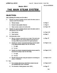
<strong><strong>234</strong>.00</strong>-3<br />
<strong>Turbine</strong>, <strong>Generator</strong> & <strong>Auxiliaries</strong> - <strong>Course</strong> <strong>234</strong><br />
STEAM VALVE HYDRAULIC CONTROL<br />
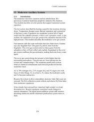
The movement of large control valves to regulate the<br />
steam supply to modern steam turbines, requires amplification<br />
of the control signals in both force and displacement to provide<br />
sufficient force to actuate the valves. Whether the<br />
control signal from the governor is mechanical or electrical,<br />
the signal is converted to a hydraulic fluid pressure for<br />
movement of the governor steam valves. The hydraulic relay<br />
and actuator has no competitor as a force amplifier for<br />
governor steam valve actuation. No other form of mechanical<br />
or electrical amplifier can develop the very high force demanded<br />
by the speed at which the governor steam valves, of<br />
modern turbines, must operate.<br />
Control<br />
Relay<br />
Feedback<br />
Valve<br />
Actuator<br />
Governor<br />
Steam<br />
Valve<br />
Steam Valve Actuation<br />
Figure 3.1<br />
March 1984 - 1 -
<strong><strong>234</strong>.00</strong>-3<br />
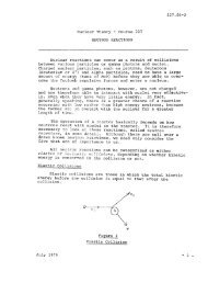
Figure 3.1 shows the basic hydraulic relay and actuator<br />
associated with a governor steam valve. The governor steam<br />
valve is opened by increasing the hydraulic pressure on the<br />
underside of the actuator piston and compressing the spring:<br />
the governor steam valve is shut by draining oil from the underside<br />
of the actuator piston and allowing the spring to expand<br />
and force the valve shut. The control relay is positioned<br />
either mechanically or electrically to supply fluid<br />
to, or drain fluid from, the actuator. Mechanical or electrical<br />
feedback is provided to position the control relay to<br />
neutral and stop the flow of fluid when the governor steam<br />
valve has moved to the desired position.<br />
There are two hydraulic fluids which are used for governor<br />
steam valve actuation:<br />
(a) turbine lubricating oil, and<br />
(b) a phosphate ester, fire resistant fluid.<br />
<strong>Turbine</strong> lubricating oil has been used for many years as<br />
the hydraulic fluid for governor steam valve actuation. Lubricating<br />
oil is readily available and does not require a separate<br />
pumping system nor a separate purifying system, when<br />
used as a control fluid. In addition, if the lubricating oil<br />
system should fail, the governor steam valves will shut since<br />
it is lubricating oil which is holding them open. Lubricating<br />
oi 1 has several disadvantages , although they were not<br />
serious enough to preclude its use as a control fluid:<br />
1. The control fluid has<br />
lUbrication. That is,<br />
properties as a control<br />
ties as a lUbricant.<br />
to be compatible with bearing<br />
the fluid is chosen not for its<br />
fluid but rather for its proper-<br />
2. The lubricating oil is subject to all manner of contamination<br />
which tends to degrade its purity. These include:<br />
fibres, water, chlorides, dirt, rust and sludge.<br />
The principle disadvantage of using lubricating oil, as<br />
a control fluid, did not become apparent until turbines became<br />
fairly large.<br />
The larger the steam flow handled by turbines, the larger<br />
the governor steam valves had to be and the greater the<br />
force necessary to move the valves at the required speeds.<br />
Since Force = (Pressure) (Area), the larger force couId be<br />
gained in one of two ways:<br />
1. increase the pressure of the control oil, or<br />
2. make the actuators larger.<br />
- 2 -
<strong><strong>234</strong>.00</strong>-3<br />
The upper limit of control oil pressure is about I, 000<br />
kPa (a). This is determined by the fire hazard involved in<br />
lubricating oil leaking from the system and soaking thermal<br />
insulation in contact with hot stearn pipes. Since it is virtually<br />
impossible to prevent oil leaks in high pressure hydraulic<br />
systems, the only effective way to eliminate this fire<br />
hazard is to keep the lubricating oil under low pressure. In<br />
addition, since the flow through the control oil system is a<br />
very small percentage of the flow to the bearings, the use of<br />
high pressure control oil requires needlessly pressurizing a<br />
large volume of oil intended for the bearings.<br />
The alternative method of developing a large force, that<br />
of making the actuator larger, also has its limitation. As<br />
the actuators get larger, the volume of oi I which must be<br />
moved to effect a response becomes greater and greater. This<br />
"reservoir effect", as it is called, results in significant<br />
time delays between the initiation of a control signal and<br />
the response, as large quantities of oil are moved about the<br />
control oil system. The time between the initiation of signal<br />
and its execution is known as the dead time or time delay<br />
and in large turbine governing systems the combined effects<br />
of mechanical inertia and oil reservoir effect can result in<br />
significant dead time.<br />
The governing system on the 540 MW Pickering NGSA turbine<br />
represents nearly the limit to which lubricating oi 1<br />
control systems can be pushed. Even in this system the exclusive<br />
use of lUbricating oil for control valve actuators<br />
would have resulted in unacceptable dead times. As a result,<br />
while the governor steam valves and emergency stop valves<br />
have hydraulic actuators, the intercept valves and steam release<br />
valves are air operated. This eliminates the long runs<br />
of control oil piping which would be necessary to supply<br />
these valves with control oil. In addition, the control oil<br />
system at Pickering NGSA is equipped with anticipator devices,<br />
to decrease the response time of the control oil system.<br />
While the use of a lUbricating oil control oil system,<br />
at Pickering NGSA has proved entirely acceptable the use of<br />
lubricating oil on larger units has not been possible.<br />
The dead time associated with large turbines using lubricating<br />
oil control oil systems has been virtually eliminated<br />
by use of high pressure, hydraulic systems, using a fire<br />
resistant fluid. The fire resistant fluid used in most electrical-hydraulic<br />
governing systems is a synthetic phosphate<br />
ester hydraulic fluid. The fluid looks like and feels like a<br />
light mineral oil. It has good lubricating properties and<br />
excellent stability. The FRF used by Ontario Hydro has an<br />
excellent combination of chemical and physical properties:<br />
low particle count, low chlorine content, high electrical resistivity<br />
and negligible corrosion of most metals. This<br />
makes it a good fluid for use in the close tolerance valves,<br />
- 3 -
<strong><strong>234</strong>.00</strong>-3<br />
limit switches and overrides which are used in electricalhydraulic<br />
governing systems. Above all, FRF virtually eliminates<br />
the fire hazard associated with conventional petroleum<br />
oils leaking onto hot steam lines.<br />
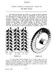
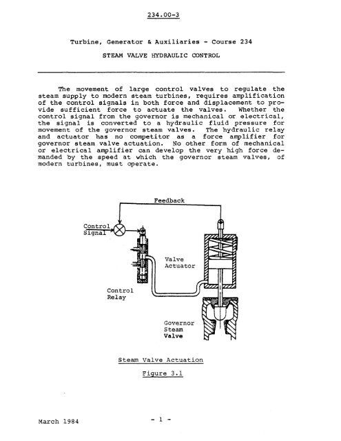
Figure 3.2 shows a typical FRF hydraulic power plant.<br />
The pumping system consists of two 100% duty centrifugal<br />
booster pumps which supply fluid at 680 kPa(g) to either of<br />
two 100% duty coolers and hence to either of two 100% duty<br />
positive displacement screw type main pumps which boost the<br />
pressure to 6800 kPa(g). Isolation valves permit maximum<br />
plant availability during on-load maintenance.<br />
All oil, and particularly the synthetic, phosphate<br />
esters used in FRF systems, have a tendency to pick up impurities,<br />
notably grit, sludge, water and chlorides which tend<br />
to accelerate system corrosion and wear. Because of the use<br />
of small, high pressure components, with close tolerances,<br />
the cleanliness of FRF systems is particularly critical.<br />
A 100 micron suction strainer is located in each centrifugal<br />
pump suction line. Full flow three micron absolute<br />
disposable element filters, fitted with differential pressure<br />
switches and internal by-passes, are located upstream and<br />
downstream of each main pump. This arrangement ensures all<br />
the fluid is filtered before entering the main pump and before<br />
entering the main hydraulic system. In addition, the<br />
fluid in the reservoir is continuously purified of moisture<br />
and acid via a fluid treatment plant which includes a vacuum<br />
dehydrator and a fuller's earth filtration plant.<br />
Immersion heaters within the fluid reservoir are used to<br />
warm the fluid during a cold start. A low capacity, low<br />
pressure pump circulates the fluid through the coolers and<br />
returns it to the reservoir. When the fluid temperature has<br />
reached a safe minimum the centrifugal and main pumps may be<br />
started.<br />
By using a separate control hydraulic system it is possible<br />
to maintain a much higher standard of fluid control, regarding<br />
temperature, viscosity and purity. It is not subject<br />
to variation in temperature to suit bearing requirements or<br />
seal oil requirements, and it is not subject to metallic pick<br />
up from bearings or moisture pick up from steam glands. However,<br />
the need for system cleanliness and hydraulic fluid<br />
purity, in high pressure, FRF governing systems is considerably<br />
more critical. Removal. of impurities which could foul<br />
and eventually score the electrical-hydraulic control valves<br />
is essential in any high pressure hydraulic system. Control<br />
valve clearances are extremely small and the valves are particularly<br />
susceptible to sticking, scoring and eventual<br />
internal leakage. In addition, electrically actuated valves<br />
- 4 -
U1<br />
Heater<br />
Reservoir<br />
Preheat<br />
Pump<br />
Fluid<br />
Treatment<br />
Plant<br />
Cooler<br />
FRF Power Plant<br />
Figure 3.2<br />
Main<br />
Pump<br />
To Hydraulic<br />
Control System<br />
N<br />
W<br />
4:>-<br />
o Iw
<strong><strong>234</strong>.00</strong>-3<br />
generally have little reserve power to free galled or sticking<br />
stems. The requirement for periodic testing of an electrical-hydraulic<br />
governing system, to insure freedom of valve<br />
movement, is doubly beneficial, in that fluid flow through<br />
the control valves keeps the valves clean. There is a great<br />
amount of practical experience which indicates that if a<br />
hydraulic control valve is not exercised for several months<br />
it will probably not operate.<br />
FRF is reasonably non-toxic to the skin and exposure<br />
through soiled clothing presents a minimal hazard although<br />
FRF entering the eyes can cause a burning sensation and cause<br />
subsequent irritation. Phosphate esters can cause fatal poisoning,<br />
however, if inhaled in large quantities or if ingested<br />
in even moderate amounts. Under usual station operating<br />
conditions, inhalation of the vapor is almost impossible due<br />
to the low volatility of the fluid. From a personal safety<br />
standpoint, FRF can be harmful and special care should be<br />
taken to prevent ingestion, inhalation or absorption through<br />
the skin by persons who handle it. However, it can be handled<br />
safely if certain precautions are taken. These include<br />
no smoking or eating while handling the fluid, use of rubber<br />
gloves and safety glasses and availability of an eye wash<br />
fountain.<br />
From an environmental standpoint, FRF can present a<br />
potential problem due to its toxicity and relative stabili<br />
ty. For this reason disposal procedures for this fluid<br />
should be carefully adhered to.<br />
ASSIGNMENT<br />
1. Define "dead time" and "reservoir effect".<br />
2. Explain why there is a limit to the size to which turbines<br />
with lubricating oil fluid control systems can be<br />
built.<br />
3. Why is hydraulic oil used for governor steam valve actuation?<br />
4. What are the advantages of an FRF fluid control system<br />
over a lubricating oil control system?<br />
5. What are the problems associated with an FRF control<br />
system?<br />
6. Discuss the need for fluid purity and cleanliness in an<br />
FRF control system.<br />
R.O. Schuelke<br />
- 6 -