
Create successful ePaper yourself
Turn your PDF publications into a flip-book with our unique Google optimized e-Paper software.
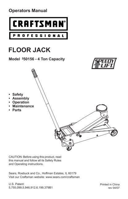
Operators Manual<br />
<strong>FLOOR</strong> <strong>JACK</strong><br />
Model 9 50156 - 4 Ton Capacity<br />
• Safety<br />
• Assembly<br />
• Operation<br />
• Maintenance<br />
• Parts<br />
CAUTION: Before using this product, read<br />
this manual and follow all its Safety Rules<br />
and Operating instructions.<br />
<strong>Sears</strong>, Roebuck and Co., Hoffman Estates, IL 60179<br />
Visit our Craftsman website: www.sears.com/craftsman<br />
U.S. Patent:<br />
5,755,099,5,946,912,6,199,379B1<br />
Printed in China<br />
rev 04/07
TABLE OF CONTENTS<br />
Warranty .....P. 2<br />
Save these instructions .....P. 2<br />
Safety instructions .....P. 3<br />
Assembly .....P. 3<br />
Operation .....P. 4 & p.5<br />
Maintenance .....P. 6<br />
Troubleshooting .....P. 7<br />
Parts .....P. 7<br />
Service .....P. 8<br />
WARRANTY<br />
CRAFTSMAN PROFESSIONAL WARRANTY<br />
If this Craftsman Professional product fails due to a defect in material or workmanship within<br />
one year from the date of purchase, return it to any <strong>Sears</strong> store or other Craftsman Professional<br />
outlet in the United States for free replacement.<br />
This warranty gives you specific legal rights, and you may also have other rights which vary<br />
from state to state.<br />
<strong>Sears</strong>, Roebuck and Co., Hoffman Estates, IL 60179<br />
SAVE THESE INSTRUCTIONS<br />
For your safety, read, understand, and follow the information provided with and on this jack.<br />
• The owner and operator of this equipment shall have an understanding of this jack and safe<br />
operating procedures before attempting to use. The owner and operator shall be aware that<br />
use and repair of this product may require special skills and knowledge. Jack instructions<br />
and safety information must be conveyed in jack operator’s native language before jack is<br />
used. If any doubt exists as to the safe and proper use of this jack, remove from service<br />
immediately.<br />
• Inspect before each use. Do not use if broken, bent, cracked, or damaged parts (including<br />
labels) are noted. Any jack that appears damaged in any way, operates abnormally or is<br />
missing parts, shall be removed from service immediately.<br />
• If the jack has been or suspected to have been subjected to a shock load (a load dropped<br />
suddenly, unexpectedly upon it), immediately discontinue use until jack has been checked<br />
by a <strong>Sears</strong> or other qualified service center. It is recommended that an annual inspection<br />
be done by qualified personnel.<br />
• Labels and Owner’s Manuals are available from <strong>Sears</strong> (see PARTS section on page 6).<br />
2
WARNING<br />
!<br />
• Study, understand, and follow all<br />
instructions with and on this device<br />
before operating this device.<br />
• Do not exceed rated capacity.<br />
• Use only on hard, level surface.<br />
• This is a lifting device only. Immediately<br />
after lifting, support the vehicle with<br />
appropriately rated vehicle stands.<br />
• Do not move or dolly the vehicle while<br />
on the jack.<br />
• Failure to heed product markings or<br />
warnings may result in personal injury<br />
or property damage.<br />
! ADVERTENCIA<br />
Leer, comprender, y seguir las instrucciones<br />
antes de utilizar el aparato. El manual<br />
de instrucciones y la informacion de<br />
seguridad deben estar comunicado en<br />
lengua del operador antes del uso. No<br />
seguir estas indicaciones puede causar<br />
danos personales o materiales.<br />
TO ASSEMBLE THE TWO PIECE<br />
HANDLE<br />
• Locate the spring pin on bottom end of upper<br />
handle and the spring pin receiver on the<br />
upper end of lower handle. (Fig. 1).<br />
• Align the spring pin with the spring pin<br />
receiver. Connect the two handle pieces<br />
together by pressing the spring pin and<br />
insert until the spring pin is locked in the<br />
spring pin receiver.<br />
SAFETY INSTRUCTIONS<br />
ASSEMBLY<br />
TO ASSEMBLE THE HANDLE INTO<br />
THE SOCKET<br />
1. Press and hold the handle socket to loosen<br />
the lock pin (Fig. 2).<br />
2. Pull out the lock pin, then release handle<br />
socket slowly.<br />
! Caution: Handle socket is spring loaded.<br />
Beware of pinching on fingers during<br />
removal of lock pin.<br />
3. Pull and hold the spring knob (Fig. 3).<br />
4. Insert the assembled handle into the<br />
socket, until it is firmly seated.<br />
5. Release spring knob to secure the handle<br />
in position.<br />
3<br />
Upper Handle<br />
FIG. 1<br />
FIG. 3<br />
Assembled<br />
Handle<br />
Spring Knob<br />
! WARNING<br />
To avoid crushing and<br />
related injuries:<br />
N E V E R w o r k o n ,<br />
under or around a load<br />
supported only by jack.<br />
ALWAYS use adequately<br />
rated jack stands.<br />
! SAFETY MESSAGE !<br />
Be sure all tools and personnel are clear<br />
before lowering load. No alterations<br />
shall be made to this product. Only<br />
attachments and/or adapters supplied by<br />
the manufacturer shall be used. Lift only<br />
on areas of the vehicle as specified by the<br />
vehicle manufacturer.<br />
NOTE: Jack stands are rated per pair<br />
unless otherwise noted.<br />
Use 1 matched pair per vehicle only.<br />
FIG. 2<br />
Spring Pin<br />
Spring Pin Receiver<br />
Lower Handle<br />
1<br />
Handle Socket<br />
Lock Pin (to hold the<br />
position of Handle<br />
Socket in packaging)<br />
Handle Socket<br />
2
KNOW YOUR <strong>JACK</strong><br />
Compare Fig. 4 illustration with your jack<br />
BEFORE operation to become familiar with<br />
the location of various jack components.<br />
Handle<br />
Socket<br />
Release Valve<br />
(inside Handle<br />
Socket, engage<br />
with Jack Handle)<br />
Jack Handle<br />
Magnetic Tool Tray<br />
(remove to access Oil Filler Plug)<br />
Oil Filler Plug<br />
(located beneath Tool Tray)<br />
Rear Castor<br />
Lifting Arm<br />
SPECIFICATIONS<br />
Rated Capacity: 4 Ton / 8000 Lbs<br />
Jack Dimensions: 27-1/4” x 13-1/4” x 6-<br />
7/16”<br />
Lifting Range: 5-3/4” ~ 19-13/16” (Approx.)<br />
(145 - 504 mm)<br />
Oil Capacity: 235 c.c.<br />
Net Weight: 89.1 Lbs (Approx.)<br />
OPERATION<br />
Saddle<br />
Front Wheel<br />
FIG. 4<br />
4<br />
BEFORE USE<br />
• Read the operator’s manual completely<br />
and familiarize yourself thoroughly with the<br />
product, its components and recognize the<br />
hazards associated with its use.<br />
• Occasionally during shipping and handling,<br />
the hydraulic oil in jack may become<br />
unstable or air may trapped in the system,<br />
both of which can interfere with the jacks<br />
lifting performance.<br />
• To stabilize the hydraulic oil, it is<br />
recommended to cycle the jack a few times<br />
without applying load:<br />
• Close release valve by turning the jack<br />
handle clockwise until tight.<br />
• Pump the handle until the jack saddle<br />
reaches its maximum height.<br />
• Open release valve by turning jack<br />
handle counter-clockwise, but no more<br />
than 1/2 full turn at a time. Allow the<br />
saddle to reach its lowest position.<br />
• Repeat the above procedure a few<br />
times.<br />
• To release air from the hydraulic system:<br />
• Open the release valve by turning the<br />
jack handle counterclockwise, but never<br />
by more than 1/2 full turn at a time.<br />
• Remove the oil filler screw from the<br />
cylinder (Fig. 4).<br />
• Rapidly pump jack handle through<br />
several full strokes.<br />
• Reinstall the oil filler screw into the<br />
cylinder again and jack is now ready to<br />
use.<br />
BEFORE EACH USE<br />
Make a visual inspection before each use<br />
of the floor jack by checking for abnormal<br />
conditions, such as cracked welds, leaks and<br />
damaged, loose, or missing parts.<br />
DAMAGE TO <strong>JACK</strong><br />
If you think jack has been subjected to an<br />
abnormal load or shock, have it inspected for<br />
damage at a <strong>Sears</strong> or other qualified service<br />
center before using it again.
OPERATING PRINCIPLES<br />
• With release valve closed, an upward<br />
stroke of the jack handle draws oil from<br />
the reservoir tank into the plunger cavity.<br />
Hydraulic pressure holds a valve closed,<br />
which keeps the oil in the plunger cavity.<br />
• A downward stroke of the jack handle<br />
releases oil into the cylinder, which forces<br />
the ram out. This raises the saddle. (NOTE:<br />
To avoid damage to the cylinder if the load<br />
exceeds the rated capacity of the jack,<br />
oil is automatically released back into<br />
the reservoir through the safety overload<br />
valve.)<br />
• When the ram reaches maximum extension,<br />
oil is bypassed back into the reservoir to<br />
prevent an over-extended ram stroke and<br />
possible damage to the jack.<br />
• Opening the release valve allows oil to<br />
flow back into the reservoir. This releases<br />
hydraulic pressure on the ram, which<br />
results in lowering the saddle.<br />
Note: The release valve must be closed<br />
for the handle to remain upright. When the<br />
release valve is opened, the handle may<br />
lower to the floor.<br />
HOW TO USE YOUR <strong>JACK</strong><br />
RAISING THE <strong>JACK</strong><br />
• Chock the vehicle wheels with appropriate<br />
devices to prevent vehicle from moving and<br />
to ensure lifting stability.<br />
• Close the release valve by turning the jack<br />
handle clockwise until tight (Fig. 4).<br />
• Refer to the vehicle manufacturer’s owner’s<br />
manual to locate approved lifting points on<br />
the vehicle. Position jack so that the saddle<br />
(Fig. 4) is centered under the load at an<br />
appropriate lift point.<br />
• Pump jack handle until saddle ALMOST<br />
contacts the vehicle. Check to see that the<br />
saddle is centered and will contact the load<br />
lifting point firmly.<br />
• Continue to pump the jack handle to lift<br />
the vehicle to the desired height. After<br />
lifting, immediately support the load with<br />
appropriately rated vehicle support stands<br />
BEFORE working on the vehicle.<br />
OPERATION<br />
LOWERING THE <strong>JACK</strong><br />
• SLOWLY open the release valve by<br />
turning the handle counterclockwise,<br />
but never more than 1/2 full turn at a<br />
time.<br />
! Warning: Rated capacity of jack stands<br />
is per pair, it is NOT the sum of individual<br />
capacities unless specifically noted to the<br />
contrary by the jack stand manufacturer.<br />
Do Not exceed rated capacity. Ensure<br />
that the vehicle support points are fully<br />
captured between the outer lugs of both<br />
jack stands. Use a matched pair of jack<br />
stands per vehicle to support one end<br />
only. Use 1 pair per vehicle only. Failure<br />
to do so may result in sudden loss of load,<br />
which may cause personal injury and/or<br />
property damage.<br />
LOWERING THE <strong>JACK</strong><br />
! Warning: To avoid crushing injuries and<br />
property damage: Keep hands and feet clear<br />
of work area when lowering load.<br />
• Raise load high enough to clear the jack<br />
stands, then carefully remove jack stands<br />
(always used in pairs).<br />
• SLOWLY open the release valve by turning<br />
the handle counterclockwise, but never<br />
more than 1/2 full turn. If the load fails to<br />
lower:<br />
• Use another jack to raise the vehicle high<br />
enough to reinstall jack stands.<br />
• Remove the affected jack and then the<br />
stands<br />
• Using the other jack, lower the load by<br />
turning the operating handle counterclockwise,<br />
but no more than 1/2 full<br />
turn.<br />
• After removing jack from under the<br />
load,push saddle down to reduce ram<br />
exposure to rust and contamination.<br />
5
MAINTAINING OIL LEVEL<br />
Important: When adding or replacing oil,<br />
ALWAYS use a good grade Hydraulic Jack oil.<br />
DO NOT use Hydraulic Brake Fluid, Alcohol,<br />
Glycerine, Detergent, Motor Oil or dirty oil.<br />
Use of an improper fluid can cause serious<br />
internal damage to your jack. We recommend<br />
Mobil DTE13M or equivalent.<br />
ADDING OIL<br />
• Position the jack on level ground and fully<br />
lower the saddle. (Ram will be all the way<br />
in). Remove oil filler plug from the reservoir<br />
(see Fig. 4 & 5).<br />
• Oil should be filled to the level of about<br />
3/16” above the inner cylinder as seen<br />
from the oil filler hole. If low, add oil as<br />
needed.<br />
• Re-install oil filler plug. The jack is now<br />
ready to use.<br />
LUBRICATION<br />
• Add lubricating oil to all moving parts as<br />
needed.<br />
PREVENTING RUST<br />
• Check ram and pump plunger (Fig. 5)<br />
every few months for any signs of rust or<br />
corrosion. Clean as needed by wiping with<br />
an oily cloth.<br />
• When not in use, ALWAYS store jack with<br />
saddle lowered all the way down.<br />
MAINTENANCE<br />
FIG. 5<br />
6<br />
ANNUAL INSPECTION<br />
To ensure that it is in optimum condition,<br />
annual inspection of the jack at a <strong>Sears</strong><br />
Service Center is recommended.<br />
REPLACING OIL<br />
• To drain oil, remove oil filler screw and open<br />
release valve. Turn jack over and drain old<br />
oil out through the oil filler hole.<br />
Note: Dispose of hydraulic oil in accordance<br />
with local regulations.<br />
• Refill with new oil through the oil filler hole.<br />
DO NOT allow dirt or foreign material to<br />
enter the hydraulic system when filling.<br />
• After refilling, remove any air from the<br />
hydraulic system by opening the release<br />
valve and rapidly pumping the jack handle<br />
several times.<br />
• Re-install oil filler screw and the jack is<br />
ready to use.
TROUBLESHOOTING<br />
PROBLEM-SOLVING HINTS<br />
Symptom Possible Causes Corrective Action<br />
Jack will not lift load • Release valve not tightly closed<br />
• Overloaded - too much weight on jack<br />
Jack bleeds off<br />
(starts to lower) after lift<br />
Jack will not lower after<br />
unloading<br />
PARTS<br />
MODEL NUMBER: 50156<br />
Not all components of the jack are replacement items, but are illustrated as a convenient<br />
reference of location and position in the assembly sequence. When ordering parts, give<br />
Model number, Serial Number and parts description. The Model Number and Serial Number<br />
are found on the lifting arm and handle socket respectively.<br />
Key Description<br />
1 Saddle Assembly<br />
2 Power Unit Assembly<br />
3 Handle Assembly<br />
4 Front Wheel Assembly<br />
5 Handle Socket Assembly<br />
6 Rear Castor Assembly<br />
7 Tool Tray<br />
8 Oil Filler Screw<br />
-- Operators Manual<br />
-- Warning Label<br />
• Release valve not tightly closed<br />
• Hydraulic unit malfunction<br />
• Oil reservoir overfilled<br />
• Linkages binding<br />
Poor lift performance • Fluid level low<br />
• Air trapped in system<br />
Will not lift to full<br />
extension<br />
FIG. 6<br />
7<br />
• Ensure release valve is tightly closed<br />
• Reduce weight on jack<br />
• Ensure release valve is tightly closed<br />
• Replace power unit assembly<br />
• Drain fluid to proper level<br />
• Clean and lubricate moving parts<br />
• Ensure proper fluid level<br />
• With ram fully retracted, open<br />
release valve and remove oil filler<br />
screw, pump handle several times to<br />
expel trapped air. Re-install oil filler<br />
screw.<br />
• Fluid level low • Ensure proper fluid level<br />
For after sale support and assistance:<br />
Call 8:00 AM - 4:45 PM CST., Monday - Friday 1-888-332-6419<br />
1<br />
8<br />
4<br />
2<br />
7<br />
3<br />
5<br />
6
Get it fixed, at your home or ours!<br />
Your Home<br />
For repair – in your home – of all major brand appliances,<br />
lawn and garden equipment, or heating and cooling systems,<br />
no matter who made it, no matter who sold it!<br />
© <strong>Sears</strong> Brands, LLC<br />
For the replacement parts, accessories and<br />
owner’s manuals that you need to do-it-yourself.<br />
For <strong>Sears</strong> professional installation of home appliances<br />
and items like garage door openers and water heaters.<br />
1-800-4-MY-HOME ®<br />
(1-800-469-4663)<br />
www.sears.com www.sears.ca<br />
Our Home<br />
For repair of carry-in items like vacuums, lawn equipment,<br />
and electronics, call or go on-line for the location of your nearest<br />
<strong>Sears</strong> Parts and Repair Center.<br />
1-800-488-1222 Call anytime, day or night (U.S.A. only)<br />
www.sears.com<br />
To purchase a protection agreement (U.S.A.)<br />
or maintenance agreement (Canada) on a product serviced by <strong>Sears</strong>:<br />
1-800-827-6665 (U.S.A.) 1-800-361-6665 (Canada)<br />
Para pedir servicio de reparación<br />
a domicilio, y para ordenar piezas:<br />
1-888-SU-HOGAR ®<br />
(1-888-784-6427)<br />
Call anytime, day or night<br />
(U.S.A. and Canada)<br />
Au Canada pour service en français:<br />
1-800-LE-FOYER MC<br />
(1-800-533-6937)<br />
www.sears.ca<br />
® Registered Trademark / TM Trademark / SM Service Mark of <strong>Sears</strong> Brands, LLC<br />
® Marca Registrada / TM Marca de Fábrica / SM Marca de Servicio de <strong>Sears</strong> Brands, LLC<br />
MC Marque de commerce / MD Marque déposée de <strong>Sears</strong> Brands, LLC