Equipment Layout - InCenter - Philips
Equipment Layout - InCenter - Philips Equipment Layout - InCenter - Philips
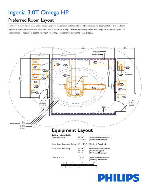
Ingenia 3.0T Omega HP Preferred Room Layout The layout shown below is based upon a typical equipment configuration and should be considered as a general design guideline. Site conditions, application requirements, customer preferences, and/or equipment configuration may significantly impact suite design and equipment layout. It is recommended to request site-specific drawings from a Philips representative early in the design process. 14'-6" [4419mm] 1 Gauss (Controlled Zone) 5 Gauss 30 Gauss 50 Gauss 100 Gauss DACC MDU 7'-0" [2134mm] CB1 8'-6" [2591mm] 0 1' 2' 4' 8' 12' 0 .5m 1m 2m 23'-0" [7010mm] Parent Wall RF Wall Finished Wall LCC RFSC GAC PV 3' W x 7' H Door min. [Recommend 4' W x 7' H] SFB HWG HEP MAG Isocenter Equipment Layout PS 4m ERB 10'-0" [3048mm] Ceiling Height Guide Equipment Room: 10' - 6" (3200 mm) Recommended 8' - 6 3/8" (2600 mm) Minimum Exam Room Suspended Ceiling: 8' - 3 3/16" (2520mm) Required Exam Room RF Ceiling: 10' - 6" (3200 mm) Recommended 10' - 0" (3050 mm) Typical 9' - 0" (2740 mm) Minimum Control Room: 9' - 10" (3000 mm) Recommended 7' - 3" (2200mm) Minimum 19'-9" [6020mm] RF Window REM OT OC 6'-6" [1981mm] ERB VFW Customer to provide/install counter 4' W x 7' H RF Door. Door to open outward
- Page 2 and 3: A B C D E F G Furnished and install
Ingenia 3.0T Omega HP<br />
Preferred Room <strong>Layout</strong><br />
The layout shown below is based upon a typical equipment configuration and should be considered as a general design guideline. Site conditions,<br />
application requirements, customer preferences, and/or equipment configuration may significantly impact suite design and equipment layout. It is<br />
recommended to request site-specific drawings from a <strong>Philips</strong> representative early in the design process.<br />
14'-6"<br />
[4419mm]<br />
1 Gauss<br />
(Controlled Zone) 5 Gauss<br />
30 Gauss<br />
50 Gauss<br />
100 Gauss<br />
DACC<br />
MDU<br />
7'-0"<br />
[2134mm]<br />
CB1<br />
8'-6"<br />
[2591mm]<br />
0 1' 2' 4'<br />
8'<br />
12'<br />
0<br />
.5m<br />
1m<br />
2m<br />
23'-0"<br />
[7010mm]<br />
Parent Wall<br />
RF Wall<br />
Finished Wall<br />
LCC RFSC<br />
GAC<br />
PV<br />
3' W x 7' H<br />
Door min.<br />
[Recommend<br />
4' W x 7' H]<br />
SFB<br />
HWG<br />
HEP<br />
MAG<br />
Isocenter<br />
<strong>Equipment</strong> <strong>Layout</strong><br />
PS<br />
4m<br />
ERB<br />
10'-0"<br />
[3048mm]<br />
Ceiling Height Guide<br />
<strong>Equipment</strong> Room: 10' - 6" (3200 mm) Recommended<br />
8' - 6 3/8" (2600 mm) Minimum<br />
Exam Room Suspended Ceiling: 8' - 3 3/16" (2520mm) Required<br />
Exam Room RF Ceiling: 10' - 6" (3200 mm) Recommended<br />
10' - 0" (3050 mm) Typical<br />
9' - 0" (2740 mm) Minimum<br />
Control Room: 9' - 10" (3000 mm) Recommended<br />
7' - 3" (2200mm) Minimum<br />
19'-9"<br />
[6020mm]<br />
RF Window<br />
REM<br />
OT<br />
OC<br />
6'-6"<br />
[1981mm]<br />
ERB<br />
VFW<br />
Customer to<br />
provide/install<br />
counter<br />
4' W x 7' H<br />
RF Door.<br />
Door to open<br />
outward
A<br />
B<br />
C<br />
D<br />
E<br />
F<br />
G<br />
Furnished and installed by <strong>Philips</strong><br />
Furnished by customer/contractor and installed by customer/contractor<br />
Installed by customer/contractor<br />
Furnished by <strong>Philips</strong> and installed by contractor<br />
Existing<br />
Future<br />
Optional item furnished by <strong>Philips</strong><br />
<strong>Equipment</strong> Designation<br />
Description<br />
<strong>Equipment</strong> Legend<br />
J<br />
H Furnished by RF Enclosure Supplier and installed by RF Enclosure Supplier<br />
Furnished by <strong>Philips</strong> and Installed by Rigging Company<br />
A OC Operator's Console 30 145 [65] 1700 [498]<br />
G OT Operator's Table --- 220 0<br />
A VFW Viewforum Workstation 10 125 [57] 1000 [293]<br />
D ERB Emergency Run-Down Button (Qty. = 2) --- 3 [1] 0<br />
J MAG Magnet Assembly --- 12850 [5830] 6800 [1993]<br />
A PS Patient Support (MT) --- 365 [165] 0<br />
A HEP Helium Gas Exhaust Pipe (exam room only) --- 4/ft [6/m] 0<br />
C HWG Helium Gas Exhaust Wave Guide --- 10 [5] 0<br />
A GAC Gradient Amplifier 787 Double Cabinet 150 2015 [914] 27900 [8177]<br />
A DACC Data Acquisition and Control Cabinet 50 585 [265] 23900 [7004]<br />
A ACC Additional Components Cabinet (TX) 50 660 [300] 6800 [1991]<br />
D LCC Liquid Cooling Cabinet 150 660 [300] 3400 [996]<br />
D MDU Mains Distribution Unit 150 605 [275] 1700 [498]<br />
A SFB System Filter Box with Covers 70 200 [990] 0<br />
G RFSC RF Coil Storage Cabinet --- 1320 [600] 0<br />
B CB1 Circuit Breaker (for system) 50 t.b.d. t.b.d.<br />
B CB2 Circuit Breaker (for Chiller) [not shown] 50 t.b.d. t.b.d.<br />
D CH Dimplex MEDKOOL 15000 AC Chiller<br />
[not shown]<br />
Max.<br />
Gauss<br />
Weight<br />
lbs [kg]<br />
Heat Load<br />
Btu/hr [W]<br />
10 2600 [1180] 188000 [55097]<br />
D REM Chiller Remote Controller 10 1 [0.5] 0<br />
A SACU System Air Cooling Unit 50 55 [25] 340 [100]<br />
D PV Patient Ventilation 150 56 [25] ---
Environmental Requirements for General <strong>Equipment</strong> Locations<br />
Heating, ventilation, air conditioning requirements concern all rooms (equipment room, magnet room, and control room) and<br />
must be maintained 24 hours a day, 7 days a week.<br />
Examination Room:<br />
Temperature: 68° to 75° F (20° to 24° C)<br />
Maximum Temperature Rate of Change: 9° F (5° C) per 10 minutes<br />
Humidity: 40% to 60%, non-condensing<br />
Air Conditioning Capacity: 6800 BTU / hr (2 kW)<br />
- Energy dissipated in the examination room will be removed from the room by an<br />
additional air exhaust system.<br />
- Gradient coil heat dissipation (3400 to 51200 BTU / hr [1 to 15 kW]) will be removed via<br />
liquid cooling of the gradient coil.<br />
<strong>Equipment</strong> Room:<br />
Temperature: 59° to 75° F (15° to 24° C)<br />
Maximum Temperature Rate of Change: 9° F (5° C) per 10 minutes<br />
Humidity: 30% to 70%, non-condensing<br />
Air Conditioning Capacity:<br />
- At Standby: 6800 BTU / hr (2 kW)<br />
- Peak Dissipation Scanning: 41000 BTU / hr (12 kW)<br />
Control Room:<br />
Temperature: 64° to 75° F (18° to 24° C)<br />
Maximum Temperature Rate of Change: 9° F (5° C) per 10 minutes<br />
Humidity: 30% to 70%, non-condensing<br />
Air Conditioning Capacity: 1700 BTU / hr (0.5 kW)<br />
Power Requirements<br />
Supply Configuration: 3 phase, 3 wire power and ground.<br />
Nominal Line Voltage: 400 VAC, 50/60 Hz or 480 VAC, 60 Hz<br />
Branch Power Requirement: 86 kVA<br />
Circuit Breaker: 3 pole, 125 A (@480 V)<br />
Remote Service Diagnostics<br />
Medical Imaging equipment to be installed by <strong>Philips</strong> is equipped with a service diagnostic feature which allows for remote and<br />
on-site service diagnostics. To establish this feature, a RJ45 type Ethernet 10/100/1000 Mbit network connector must be<br />
installed. Access to customer's network via their remote access server is needed for Remote Service Network (RSN)<br />
connectivity. All costs with this feature are the responsibility of the customer.<br />
© Koninklijke <strong>Philips</strong> Electronics N.V. 2011.<br />
All rights reserved.<br />
Reproduction in whole or in part is<br />
prohibited without prior written consent of<br />
the copyright holder.<br />
Rev. 11.00


