Quickfly Operating Manual - Meyer Sound Laboratories Inc.
Quickfly Operating Manual - Meyer Sound Laboratories Inc.
Quickfly Operating Manual - Meyer Sound Laboratories Inc.

Create successful ePaper yourself
Turn your PDF publications into a flip-book with our unique Google optimized e-Paper software.
attachments must be made at both the top and bottom of<br />
the columns being aligned. Also, care must be taken to<br />
keep the points at the top of each row equally loaded.<br />
Both requirements are accomplished easily if all the bolts<br />
are installed at one time while the cabinets are hanging<br />
one to two feet above the ground and have been aligned<br />
vertically. Failure to follow these precautions may result in<br />
damage to the MRF-6 and/or the alignment bolts. If vertical<br />
offset beyond 0 degrees is required between two or<br />
more rows of cabinets, the frames cannot be bolted<br />
together horizontally. In such cases, each vertical column<br />
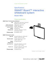
of loudspeakers must be hung independently. Care must be<br />
taken when setting the rigging points to keep the cabinets<br />
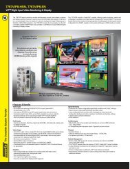
in proper acoustic alignment to one another (Figure<br />
10a, below).<br />
Figure 10a MSL-6s in acoustic alignment<br />
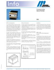
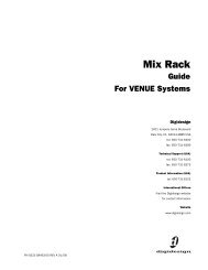
5.0 MRFCB-6 CONNECTING BAR KIT PART NO. 40.053.049.01<br />
Figure 11 The Long and Short MRFCB-6 Connecting Bar<br />
5.1 OVERVIEW<br />
The MRFCB-6 connecting bar kit consists of two short and<br />
two front connecting bars along with all set pins and<br />
linchpins for joining two MRF-6 frames together vertically.<br />
4.8 TRANSITION TO L-TRACK-EQUIPPED TYPE 4<br />
LOUDSPEAKERS<br />
Transitioning between the MRF-6 and an L-Track equipped<br />
Type 4 loudspeaker can be achieved in two ways. The first<br />
option is to use the RCL-1 Connection Link at both front<br />
and rear corners of a Type 4 loudspeaker. This will keep<br />
the cabinets in horizontal alignment with no vertical<br />
splay. Other Type 4 cabinets can be attached to create the<br />
desired horizontal coverage (See the Appendix) Figure<br />
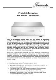
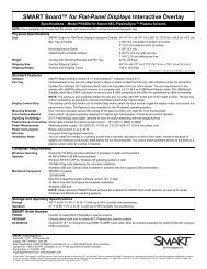
10b shows this type of transition. Note that the L-Track<br />
clips are attached to the MRF-6’s horizontal L-Track in<br />
opposing orientation: the L-Track clip is attached to the<br />
L-Track with the hammerlock to the left on the left hand<br />
side attachment and to the right on the right hand side<br />
attachment. This produces a neat and secure transition.<br />
Figure 10b<br />
The second option is to use RCL-1 Connection Links at the<br />
rear corners of the Type 4 cabinet but substitute one of<br />
the MCC- Series Front Connection Chains for front attachment<br />
to allow vertical splay. See the Appendix for a table<br />
of recommended splay angles.<br />
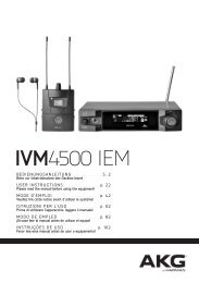
The front connecting bars provide multiple holes for<br />
adjusting vertical offset from 0° to 10°.<br />
5.2 KIT CONTENTS<br />
2 x Part No. Short connecting bars<br />
(MSPN 61.053.046.01)<br />
2 x Part No. Long connecting bars<br />
(MSPN 61.053.046.02)<br />
8 x Part No. Set pins (MSPN 61.053.054.01)<br />
8 x Part No. linchpins (MSPN 124.049)<br />
Cabinets can be attached to one another vertically using<br />
the optional connecting bar kits (MRFCB-6). These front<br />
bars allow adjustment of the vertical splay between cabinets,<br />
in two-degree increments, up to ten degrees (Figures<br />
10