Crestron QM-RMC Room Media Controller Operations Guide
Crestron QM-RMC Room Media Controller Operations Guide
Crestron QM-RMC Room Media Controller Operations Guide

You also want an ePaper? Increase the reach of your titles
YUMPU automatically turns print PDFs into web optimized ePapers that Google loves.
<strong>Crestron</strong> <strong>QM</strong>-<strong>RMC</strong><br />
<strong>Room</strong> <strong>Media</strong> <strong>Controller</strong><br />
<strong>Operations</strong> <strong>Guide</strong>
This document was prepared and written by the Technical Documentation department at:<br />
<strong>Crestron</strong> Electronics, Inc.<br />
15 Volvo Drive<br />
Rockleigh, NJ 07647<br />
1-888-CRESTRON<br />
All brand names, product names and trademarks are the property of their respective owners.<br />
©2003 <strong>Crestron</strong> Electronics, Inc.
<strong>Crestron</strong> <strong>QM</strong>-<strong>RMC</strong> <strong>Room</strong> <strong>Media</strong> <strong>Controller</strong><br />
Contents<br />
<strong>Room</strong> <strong>Media</strong> <strong>Controller</strong>: <strong>QM</strong>-<strong>RMC</strong> 1<br />
Introduction ..........................................................................................................1<br />
Features and Functions...........................................................................1<br />
Specifications.........................................................................................3<br />
Physical Description...............................................................................4<br />
Memory..................................................................................................7<br />
Industry Compliance ..............................................................................9<br />
Setup.....................................................................................................................9<br />
Hardware Hookup ..................................................................................9<br />
Establishing Communication with the <strong>QM</strong>-<strong>RMC</strong>................................10<br />
Troubleshooting Communications .......................................................13<br />
Compiling and Uploading a Program to the Control System...............15<br />
Uploading Web pages to the <strong>QM</strong>-<strong>RMC</strong>...............................................16<br />
Updating the Operating System ...........................................................17<br />
Advanced Console Commands ............................................................18<br />
Programming the <strong>QM</strong>-<strong>RMC</strong>...............................................................................18<br />
Programming with the <strong>Crestron</strong> AppBuilder .......................................19<br />
Programming with SIMPL Windows...................................................19<br />
Problem Solving.................................................................................................25<br />
Troubleshooting ...................................................................................25<br />
Further Inquiries...................................................................................28<br />
Firmware Upgrades..............................................................................28<br />
Future Updates .....................................................................................28<br />
Software License Agreement..............................................................................29<br />
Return and Warranty Policies.............................................................................31<br />
Merchandise Returns / Repair Service .................................................31<br />
CRESTRON Limited Warranty ...........................................................31<br />
<strong>Operations</strong> <strong>Guide</strong> – DOC. 6161 Contents • i
<strong>Crestron</strong> <strong>QM</strong>-<strong>RMC</strong> <strong>Room</strong> <strong>Media</strong> <strong>Controller</strong><br />
<strong>Room</strong> <strong>Media</strong> <strong>Controller</strong>:<br />
<strong>QM</strong>-<strong>RMC</strong><br />
Introduction<br />
Features and Functions<br />
The <strong>QM</strong>-<strong>RMC</strong> is a low cost IP management tool to help facilities easily control<br />
and monitor A/V devices. This powerful, compact control system enables serial,<br />
IR, and Ethernet devices such as projectors, switchers, TVs, and other A/V<br />
equipment to be controlled over IP networks. <strong>QM</strong>-<strong>RMC</strong> is an ideal solution for<br />
colleges, universities, and other multi-room installations. It is a full-scale control<br />
system with complete support of all <strong>Crestron</strong> e-Control ® 2 and power<br />
applications.<br />
Functional Summary<br />
• Powerful 2-Series processor, based on Motorola’s ColdFire ®<br />
technology, with non-volatile memory.<br />
• Native e-mail client<br />
• Supports DHCP, DNS and SSL (refer to the notes following this<br />
summary).<br />
• Supports XPanel IE/EXE/PDA control (<strong>Crestron</strong> e-Control ® 2).<br />
• Programmable logic via SIMPL Windows, including SIMPL+ ®<br />
• Flash memory and DRAM.<br />
• Two bi-directional COM ports with built-in serial drivers for<br />
controlling devices over RS-232.<br />
• One IR port - compatible with <strong>Crestron</strong> ST-SPL IR-Splitter, for IR-<br />
Control of up to five different devices, programmable via the hundreds<br />
of IR device drivers available in the <strong>Crestron</strong> databases.<br />
• Four digital input ports for direct connection of power sensors, pressure<br />
sensors, door sensors, room occupancy sensor, etc.<br />
• A 10/100 Ethernet LAN port with built-in Web server and support for<br />
DHCP; and support for all <strong>Crestron</strong> e-Control power applications and<br />
<strong>Crestron</strong> <strong>Room</strong>View A/V facility monitoring and management<br />
software.<br />
• When used with <strong>Crestron</strong> <strong>Room</strong>View, provides remote power<br />
control and management of A/V devices, including: monitoring lamp<br />
life of projectors, device status to ensure proper equipment operations,<br />
room occupancy, equipment use log, and device and room security.<br />
<strong>Operations</strong> <strong>Guide</strong> – DOC. 6161 <strong>Room</strong> <strong>Media</strong> Processor: <strong>QM</strong>-<strong>RMC</strong> • 1
<strong>Room</strong> <strong>Media</strong> <strong>Controller</strong> <strong>Crestron</strong> <strong>QM</strong>-<strong>RMC</strong><br />
NOTE: DHCP (Dynamic Host Configuration Protocol) is a network protocol<br />
that enables a DHCP server to automatically assign an IP address to an<br />
individual computer's TCP/IP stack software. DHCP assigns a number<br />
dynamically from a defined range of numbers (i.e., a scope) configured for a<br />
given network.<br />
NOTE: DNS stands for Domain Name Service (or System). Its primary use is<br />
to translate, or resolve, the IP number for a computer (e.g., 129.79.5.208) from<br />
an alphanumeric name.<br />
NOTE: SSL, or Secure Socket Layer, is the most commonly used protocol for<br />
Web security. In addition to providing security for HTTP (Web hypertext)<br />
transactions, SSL works with other TCP/IP standards such as IMAP mail and<br />
LDAP directory access. For a security standard such as SSL to work, the<br />
browser and the Web server must both be configured to use it.<br />
The <strong>QM</strong>-<strong>RMC</strong> is a stand-alone processor with all of the capabilities of a 2-<br />
Series processor, without the Cresnet ® port. The <strong>QM</strong>-<strong>RMC</strong> is programmed with<br />
SIMPL Windows and has a built-in web server, native email client, supports<br />
DHCP and DNS, as well as SSL (Secure Socket Layer - Industry standard<br />
network security native to all <strong>Crestron</strong> 2-Series control systems). Versatile<br />
enough to operate as a standalone control system, the <strong>QM</strong>-<strong>RMC</strong> is also ideally<br />
suited for integration with an MP2E, MC2E or the CP2E low-cost room control<br />
solutions.<br />
The <strong>QM</strong>-<strong>RMC</strong> provides a 10/100 Ethernet port with support for DHCP and a<br />
built-in Web server, so users can control serial devices from any computer on<br />
the LAN, WAN, or even the Internet. Create customized Web pages using<br />
<strong>Crestron</strong> VisionTools ® Pro-e software, eliminating the need for third-party Web<br />
page design software.<br />
In fact, the new <strong>Crestron</strong> e-Control ® 2 technology gives Web pages the same<br />
look and feel as <strong>Crestron</strong>’s TPS ISYS ® touchpanel pages, with almost zero<br />
latency. This means you can add multi-mode buttons, gauges, sliders, subpages<br />
and high-resolution graphics to your Web page projects, and the runtime<br />
performance will be the same as with TPS touchpanels. <strong>Crestron</strong> e-Control 2<br />
also generates standalone executables allowing users to launch from their<br />
Windows ® desktop, or Windows XP/Windows, CE StrongARM, XScale, Web<br />
Tablet/Handheld PC, or Pocket PC 2002 PDA.<br />
Some applications that <strong>QM</strong>-<strong>RMC</strong> can be used to monitor include: remote power<br />
control/management of A/V devices, lamp life of projectors, device status to<br />
ensure proper equipment operations, room occupancy, and room and/or device<br />
security. It can also be used to remotely lock out projector/display controls from<br />
unwanted users or to log equipment usage. Combined with the power of<br />
<strong>Crestron</strong> <strong>Room</strong>View software, hundreds of rooms with <strong>QM</strong>-<strong>RMC</strong>s can be<br />
centrally monitored as to the status of all the above-mentioned functions by<br />
multiple AV-personnel using PC/laptops connected to their LAN/WAN/Internet.<br />
2 • <strong>Room</strong> <strong>Media</strong> Processor: <strong>QM</strong>-<strong>RMC</strong> <strong>Operations</strong> <strong>Guide</strong> - DOC. 6161
<strong>Crestron</strong> <strong>QM</strong>-<strong>RMC</strong> <strong>Room</strong> <strong>Media</strong> <strong>Controller</strong><br />
Specifications<br />
Specifications for the <strong>QM</strong>-<strong>RMC</strong> are given in the following table.<br />
<strong>QM</strong>-<strong>RMC</strong> Specifications<br />
SPECIFICATION DETAILS<br />
CPU 32-Bit Motorola 5272 ColdFire ® Processor<br />
Processor Speed 63 MIPS (Dhrystone 2.1 Benchmark)<br />
Memory 36MB (4MB flash, 32MB SDRAM, 256KB NVRAM) 1<br />
Ports/Connectors 2<br />
LAN One – RJ-45 10/100 BaseT Ethernet port<br />
INFRARED – Serial<br />
Input<br />
INPUT<br />
COM (A & B)<br />
One – 2-Position Mini connector IR port (Supports up to five<br />
IR devices)<br />
One – 5-Position Mini connector (four inputs and GND)<br />
Two – DB9 bidirectional serial ports (RS-232) baud rate up to<br />
115,200 bps (Port B is used for initial communication and<br />
setup).<br />
12VDC One – Male receptacle for external power pack (included)<br />
Reset Buttons<br />
HW-R Initiates system hardware reset<br />
SW-R System restart with or without program<br />
Power Requirements 6 W (0.5 Amp @ 12 VDC) power supply included<br />
Initial Firmware Release 3.052<br />
Environmental<br />
Temperature<br />
41° to 113°F (5° to 45°C)<br />
Environmental Humidity 10% to 90% RH (non-condensing)<br />
Dimensions & Weight Height: 1.43 in (3.63 cm)<br />
Width: 4.65 in (11.81 cm)<br />
Depth: 5.24 in (13.31 cm)<br />
Weight: 1.34 lb (0.61 kg)<br />
1. For more information on system memory usage, refer to “Memory” on page 7.<br />
2. For more information on controls, ports, and indicators, refer to “Physical Description” on page 4.<br />
<strong>Operations</strong> <strong>Guide</strong> – DOC. 6161 <strong>Room</strong> <strong>Media</strong> Processor: <strong>QM</strong>-<strong>RMC</strong> • 3
<strong>Room</strong> <strong>Media</strong> <strong>Controller</strong> <strong>Crestron</strong> <strong>QM</strong>-<strong>RMC</strong><br />
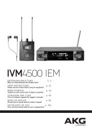
Physical Dimensions<br />
1.43 in<br />
(3.63 cm)<br />
Physical Description<br />
The <strong>QM</strong>-<strong>RMC</strong> is housed in a black enclosure with labels on the front and rear<br />
panels. On the front of the unit there are six LEDs for indicating the unit’s<br />
current status, two LEDs on the LAN connector, and two reset buttons. All<br />
connections, except for the Ethernet and power connections, are made on the<br />
back of the unit. There are four rubber feet on the base of the unit for stability<br />
and to prevent slippage. Refer to the physical views shown below.<br />
Front and Rear Views<br />
5.24 in<br />
(13.31 cm)<br />
4.65 in<br />
(11.81 cm)<br />
4 • <strong>Room</strong> <strong>Media</strong> Processor: <strong>QM</strong>-<strong>RMC</strong> <strong>Operations</strong> <strong>Guide</strong> - DOC. 6161
<strong>Crestron</strong> <strong>QM</strong>-<strong>RMC</strong> <strong>Room</strong> <strong>Media</strong> <strong>Controller</strong><br />
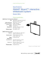
Controls and Indicators<br />
The <strong>QM</strong>-<strong>RMC</strong> front panel indicators and controls are described as follows.<br />
LAN<br />
COM A<br />
COM A<br />
COM B<br />
IR<br />
INPUT<br />
LED indicates COM A port activity.<br />
COM B<br />
HW-R SW-R PWR<br />
ACT<br />
12VDC<br />
0.5A<br />
<strong>QM</strong>-<strong>RMC</strong><br />
LED indicates COM B port activity. Constant blinking indicates that the port is<br />
used for remote console connection.<br />
IR<br />
LED indicates IR port activity.<br />
INPUT<br />
LED indicates input activity.<br />
HW-R<br />
Pressing this button initiates system hardware reset. (Same effect as<br />
disconnecting and reconnecting power.)<br />
SW-R<br />
Pressing this button in combination with the HW-R button performs a system<br />
restart without loading the program (refer to “Troubleshooting<br />
Communications” on page 13). Press HW-R momentarily while pressing and<br />
holding SW-R to reboot.<br />
Pressing SW-R alone while the system is running restarts the program, and puts<br />
the unit at a default IP address. COM B port becomes a remote console<br />
connection.<br />
PWR (Power)<br />
This green LED illuminates when the unit is connected to and receives 12 VDC<br />
power from an external power pack.<br />
ACT (LAN)<br />
This LED illuminates when the <strong>QM</strong>-<strong>RMC</strong> communicates with any device on the<br />
network.<br />
<strong>Operations</strong> <strong>Guide</strong> – DOC. 6161 <strong>Room</strong> <strong>Media</strong> Processor: <strong>QM</strong>-<strong>RMC</strong> • 5
<strong>Room</strong> <strong>Media</strong> <strong>Controller</strong> <strong>Crestron</strong> <strong>QM</strong>-<strong>RMC</strong><br />
LAN<br />
Yellow Green<br />
12VDC<br />
0.5A<br />
8 1<br />
Front Panel Ports<br />
The <strong>QM</strong>-<strong>RMC</strong> front panel ports are illustrated and described as follows.<br />
LAN<br />
An 8-position RJ-45 port (labeled LAN) is used for connection to the Ethernet,<br />
providing local area network or Web access (cable is not supplied). The port<br />
also contains two light-emitting diodes (LEDs). The green LED on the right<br />
side of the port is a link status LED and illuminates when the card is connected<br />
to a working network. The yellow LED on the left side flashes to indicate<br />
Ethernet activity. Refer to the following table for the Ethernet connector<br />
signals and use an appropriate cable.<br />
LAN 8-Position RJ-45 Connector Specifications<br />
PIN SIGNALS<br />
1 TD +<br />
2 TD -<br />
3 RD +<br />
4 Connected to pin 5<br />
5 Connected to pin 4<br />
6 RD -<br />
7 Connected to pin 8<br />
8 Connected to pin 7<br />
NOTE: To determine the location of pin 1, hold the cable so that the end of<br />
the eight pin modular jack is facing away from you, with the clip up and<br />
copper side down. Pin 1 is on the far right.<br />
Default Ethernet Ports<br />
80 = Web<br />
41794 = <strong>Crestron</strong> Com<br />
41795 = Viewport/Debug<br />
PIN 1<br />
PIN 8<br />
12VDC, 0.5A (Power Supply)<br />
This male connector can be used to supply 12 VDC power to the <strong>QM</strong>-<strong>RMC</strong><br />
from an external power pack (included).<br />
CAUTION: Use only <strong>Crestron</strong> power supplies for <strong>Crestron</strong> equipment.<br />
Failure to do so could cause equipment damage or void the <strong>Crestron</strong> warranty.<br />
6 • <strong>Room</strong> <strong>Media</strong> Processor: <strong>QM</strong>-<strong>RMC</strong> <strong>Operations</strong> <strong>Guide</strong> - DOC. 6161
<strong>Crestron</strong> <strong>QM</strong>-<strong>RMC</strong> <strong>Room</strong> <strong>Media</strong> <strong>Controller</strong><br />
INPUT<br />
1 2 3 4 G<br />
IR<br />
S G<br />
COM A<br />
COM B<br />
Rear Panel Ports<br />
The <strong>QM</strong>-<strong>RMC</strong> rear panel ports are illustrated and described as follows.<br />
INPUT<br />
This connector provides four software programmable digital inputs. Inputs are<br />
Schmidt trigger type (nominal 2.5 V threshold) with 24 V input tolerance. For<br />
detailed information, refer to “Slot 2: C21-DI04” on page 21.<br />
Digital inputs are rated 0 – 24 VDC, 20K ohms input impedance.<br />
IR<br />
A 2-position mini-connector is a mini-implementation of a single PRO2 IR<br />
port. The output is labeled S (signal) and G (ground). Infrared output is rated<br />
up to 1.2 MHz, at data rates up to 9600 baud. Serial protocols include oneway<br />
RS-232. For detailed information, refer to “Slot 1: C2I-IR1” on page 20.<br />
COM (A & B)<br />
These two DB9 (male) software programmable, bi-directional serial ports are<br />
available for RS-232 communication, with hardware and software<br />
handshaking and modem control. Speeds are rated up to 115,200 bps.<br />
COM B is used as the console port.<br />
Standard COM DB9 Pinout<br />
PIN DIRECTION DESCRIPTION<br />
1 TO <strong>QM</strong>-<strong>RMC</strong> (DCD) Data Carrier Detect<br />
2 To <strong>QM</strong>-<strong>RMC</strong> (RXD) Receive Data<br />
3 From <strong>QM</strong>-<strong>RMC</strong> (TXD) Transmit Data<br />
4 From <strong>QM</strong>-<strong>RMC</strong> (DTR) Data Terminal Ready<br />
5 Common (SG) Signal Ground<br />
7 From <strong>QM</strong>-<strong>RMC</strong> (RTS) Request To Send<br />
8 To <strong>QM</strong>-<strong>RMC</strong> (CTS) Clear To Send<br />
9 To <strong>QM</strong>-<strong>RMC</strong> (RI) Ring Indicator<br />
Memory<br />
The <strong>QM</strong>-<strong>RMC</strong> has 36MB of built-in memory (non-volatile and volatile). The<br />
total of 36MB is specified as follows: 4MB flash (non-volatile), 32MB SDRAM<br />
(volatile), and 256KB NVRAM (battery backed up). Flash memory contains the<br />
file system inside the 2-Series control engine. Non-volatile memory contains<br />
information that is retained after the loss of electrical power. Volatile memory is<br />
lost after a power failure. Refer to the following lists for a breakdown of<br />
memory usage for program-related information stored in the unit.<br />
<strong>Operations</strong> <strong>Guide</strong> – DOC. 6161 <strong>Room</strong> <strong>Media</strong> Processor: <strong>QM</strong>-<strong>RMC</strong> • 7
<strong>Room</strong> <strong>Media</strong> <strong>Controller</strong> <strong>Crestron</strong> <strong>QM</strong>-<strong>RMC</strong><br />
Flash<br />
1. SIMPL Program (.smw)<br />
2. SIMPL+ Modules (.usp/.ush)<br />
3. Operating System (.cuz file)<br />
The 4MB flash memory consists of approximately 1.5MB used for firmware,<br />
and approximately 2.5MB available for SIMPL, SIMPL+, and Web pages. The<br />
files that reside in flash conform to a flat directory structure. The following table<br />
presents the structure of the overall file system.<br />
Flash File Structure<br />
TOP LEVEL SECONDARY LEVEL DESCRIPTION<br />
\ Root of the file system<br />
DISPLAY Legacy directory used in<br />
<strong>Crestron</strong> Isys ® panels to<br />
hold display lists<br />
SYS Contains various system<br />
configuration files<br />
SETUP Legacy directory used in<br />
<strong>Crestron</strong> Isys ® panels to<br />
hold display lists<br />
HTML Web pages<br />
SIMPL Control system program<br />
files<br />
SPLUS SIMPL+ module files<br />
USER Used for user-defined files<br />
MAILBOX Directory contains the user<br />
mailbox file<br />
CFØ The mounting point for the<br />
compact flash files.<br />
\CFØ\DISPLAY Directory used to hold<br />
display files<br />
\nvram The mounting point for<br />
NVRAM disk files<br />
Although the file system is case insensitive, the case is preserved to maintain file<br />
checksums.<br />
Non-volatile<br />
1. SIMPL+ Variables (Default if no options are specified, or using<br />
"nonvolatile" qualifier or #DEFAULT_NONVOLATILE)<br />
2. Signals explicitly written to NVRAM* (by symbols such as Analog<br />
RAM, Analog RAM from database, Serial RAM, Serial RAM from<br />
database, Analog Non-volatile Ramp, Digital RAM, etc.)<br />
*Commonly used for presets (volume/lighting/dial #s).<br />
3. Portions of the NVRAM may be set aside for implementing an<br />
“NVRAM Disk”. This can be used to provide file system access from<br />
SIMPL+.<br />
8 • <strong>Room</strong> <strong>Media</strong> Processor: <strong>QM</strong>-<strong>RMC</strong> <strong>Operations</strong> <strong>Guide</strong> - DOC. 6161
<strong>Crestron</strong> <strong>QM</strong>-<strong>RMC</strong> <strong>Room</strong> <strong>Media</strong> <strong>Controller</strong><br />
Setup<br />
NOTE: If you extract NVRAM values to a file (Viewport, File transfer | Save<br />
NVRAM to File), to simplify restoring them in the event of file corruption or to<br />
distribute to identical control systems, remember that NVRAM values are position<br />
sensitive in the program. When saving the NVRAM is crucial to your application,<br />
it is recommended to place all symbols and/or modules that use NVRAM at the<br />
beginning of your program. When NVRAM (.nvr file) is re-installed, all the values<br />
should line up with the program. If the program is modified, and new logic that<br />
uses NVRAM is placed before any older symbols using NVRAM, the previously<br />
stored values will not line up and your presets will have to be re-entered.<br />
NOTE: The new NVRAMDISK command (available in CUZ files later than<br />
3.030), will fail unless it can determine the amount of NVRAM used by the<br />
program, to ensure that the NVRAM is not overwritten. Programs compiled in<br />
SIMPL Windows version 2.04.11 or later can provide this information. In the<br />
event of a failure of the NVRAMDISK command, ensure that your program has<br />
been recompiled in an appropriate version of SIMPL Windows and reloaded.<br />
Volatile (DRAM)<br />
1. Digital, analog and serial signal values<br />
2. SIMPL+ Variables (Default if no options are specified, or if "volatile"<br />
qualifier is used, or #DEFAULT_VOLATILE is used)<br />
DRAM is used by the operating system for dynamic storage of variables, signals<br />
and other constructs used at runtime. The actual amount of DRAM used at any<br />
given time depends on the particular program that is running, i.e., usage is<br />
variable, or dynamic, during normal operation.<br />
Industry Compliance<br />
As of the date of manufacture, the <strong>QM</strong>-<strong>RMC</strong> has been tested and found to<br />
comply with specifications for CE marking and standards per EMC and<br />
Radiocommunications Compliance Labelling (N11785).<br />
NOTE: This device complies with part 15 of the FCC rules. Operation is<br />
subject to the following two conditions: (1) this device may not cause harmful<br />
interference, and (2) this device must accept any interference received, including<br />
interference that may cause undesired operation.<br />
Hardware Hookup<br />
Refer to the following hookup diagram and, aside from attaching power last,<br />
complete the connections in any order.<br />
NOTE: To prevent overheating, do not operate this product in an area that<br />
exceeds the environmental temperature range listed in the specifications table.<br />
Consideration must be given if installed in a closed or multi-unit rack assembly<br />
since the operating ambient temperature of the rack environment may be greater<br />
than the room ambient. Contact with thermal insulating materials should be<br />
avoided on all sides of the unit.<br />
<strong>Operations</strong> <strong>Guide</strong> – DOC. 6161 <strong>Room</strong> <strong>Media</strong> Processor: <strong>QM</strong>-<strong>RMC</strong> • 9
<strong>Room</strong> <strong>Media</strong> <strong>Controller</strong> <strong>Crestron</strong> <strong>QM</strong>-<strong>RMC</strong><br />
NOTE: The maximum continuous current from equipment under any external<br />
load conditions shall not exceed a current limit that is suitable for the minimum<br />
wire gauge used in interconnecting cables. The ratings on the connecting unit's<br />
supply input should be considered to prevent overloading the wiring.<br />
Front Connections<br />
LAN<br />
Rear Connections<br />
INPUT<br />
1 2 3 4 G<br />
COM A<br />
COM B<br />
IR<br />
INPUT<br />
HW-R SW-R PWR<br />
ACT<br />
IR COM A COM B<br />
S G<br />
CRESTRON ELECTRONICS INC. ROCKLEIGH, N.J. 07647<br />
Four Analog/Digital<br />
Inputs<br />
LAN Connection Power Connection<br />
IR Output<br />
Connection<br />
Serial Port<br />
Connections<br />
12VDC<br />
0.5A<br />
<strong>QM</strong>-<strong>RMC</strong><br />
NOTE: COM B is shared for device control and serial console connection.<br />
Establishing Communication with the <strong>QM</strong>-<strong>RMC</strong><br />
Before uploading a program to the <strong>QM</strong>-<strong>RMC</strong> or performing diagnostic<br />
functions, you must connect the <strong>QM</strong>-<strong>RMC</strong> system to the PC. The connection<br />
can be either serial or TCP/IP.<br />
NOTE: For laptops and other PCs without a built-in RS-232 port, <strong>Crestron</strong><br />
recommends the use of PCMCIA cards, rather than USB-to-serial adapters. If a<br />
USB-to-serial adapter must be used, <strong>Crestron</strong> has tested the following devices<br />
with good results:<br />
Belkin (large model) F5U103<br />
I/O Gear GUC232A<br />
Keyspan USA-19QW<br />
Other models, even from the same manufacturer, may not yield the same results.<br />
Serial Connection<br />
Connect the COM B port on the <strong>QM</strong>-<strong>RMC</strong> control system to one of the COM<br />
ports (usually COM 1) on the PC. Use a null-modem RS-232 cable with DB9<br />
female connectors on both ends. Most commercially available cables are<br />
10 • <strong>Room</strong> <strong>Media</strong> Processor: <strong>QM</strong>-<strong>RMC</strong> <strong>Operations</strong> <strong>Guide</strong> - DOC. 6161
<strong>Crestron</strong> <strong>QM</strong>-<strong>RMC</strong> <strong>Room</strong> <strong>Media</strong> <strong>Controller</strong><br />
acceptable; they should have at least five pins for transmit, receive, ground, and<br />
hardware handshaking (pins 2, 3, 5, 7 and 8).<br />
Serial console connection may be established only if SW-R button is pressed<br />
and held during power up, or if pressed and held at the same time HW-R is<br />
momentarily pressed.<br />
NOTE: The Viewport utility performs multiple system tasks, primarily via an<br />
RS-232 or TCP/IP connection between the control system and a PC. It is used to<br />
observe system processes, upload new operating systems and firmware, change<br />
system and network parameters, and communicate with network device consoles<br />
and touchpanels, among many other tasks. Viewport can also function as a<br />
terminal emulator for generic file transfer. All of these functions are accessed<br />
through the commands and options in the Viewport menus. Viewport is<br />
available through the SIMPL Windows and <strong>Crestron</strong> VisionTools ® (VT Pro-e)<br />
software.<br />
Open the <strong>Crestron</strong> Viewport and click Setup | Communication Settings to<br />
display the “Port Settings” window. Then click RS-232 as the connection type.<br />
NOTE: Changes in communication settings are not saved after the <strong>QM</strong>-<strong>RMC</strong> is<br />
rebooted. It reverts to default settings.<br />
The PC communication settings specified here should match the protocol that<br />
the <strong>QM</strong>-<strong>RMC</strong> expects. The settings are as follows:<br />
• Port = COM 1 through COM 8. Select the correct COM port on the PC.<br />
• Baud rate = 115200 (You can set the PC and the control system to a<br />
different baud rate, by using the Functions | Set Baud Rate command.<br />
• Parity = None.<br />
• Number of data bits = 8.<br />
• Number of stop bits = 1.<br />
• Hardware handshaking (RTS/CTS) enabled.<br />
• Software handshaking (XON/XOFF) not enabled.<br />
<strong>Operations</strong> <strong>Guide</strong> – DOC. 6161 <strong>Room</strong> <strong>Media</strong> Processor: <strong>QM</strong>-<strong>RMC</strong> • 11
<strong>Room</strong> <strong>Media</strong> <strong>Controller</strong> <strong>Crestron</strong> <strong>QM</strong>-<strong>RMC</strong><br />
“Port Settings” Window:<br />
Default PC Settings for RS-232 Communication with the <strong>QM</strong>-<strong>RMC</strong><br />
To verify communication, click Diagnostics | Establish Communications<br />
(Find Rack). This should display a window that gives the COM port and baud<br />
rate.<br />
TCP/IP Connection<br />
Before you can communicate with the <strong>QM</strong>-<strong>RMC</strong> over TCP/IP, you must use the<br />
RS-232 connection just described to configure the unit’s TCP/IP settings. Obtain<br />
the static address from the network administrator.<br />
1. Open Viewport and click Functions | Set Control System IP<br />
Information.<br />
2. Enter the IP address, IP mask and default router in the text fields. All of<br />
these terms are explained in detail in the <strong>Crestron</strong> e-Control Reference<br />
<strong>Guide</strong>, Doc. 6052. The latest version is available as a PDF on the<br />
<strong>Crestron</strong> website (www.crestron.com).<br />
3. Click OK to set the new IP information.<br />
Once you have assigned the IP settings, you can continue to communicate with<br />
the <strong>QM</strong>-<strong>RMC</strong> using the RS-232 connection, or you can establish a TCP/IP<br />
connection.<br />
For TCP/IP, use CAT5 straight through cables with 8-pin RJ-45 connectors to<br />
connect the LAN port on the <strong>QM</strong>-<strong>RMC</strong> and the LAN port on the PC to the<br />
Ethernet hub. Alternatively, you can use a CAT5 crossover cable to connect the<br />
two LAN ports directly, without using a hub. The following figure illustrates<br />
pinouts for straight through and crossover RJ-45 cables. Pins 4, 5, 7, and 8 are<br />
not used.<br />
12 • <strong>Room</strong> <strong>Media</strong> Processor: <strong>QM</strong>-<strong>RMC</strong> <strong>Operations</strong> <strong>Guide</strong> - DOC. 6161
<strong>Crestron</strong> <strong>QM</strong>-<strong>RMC</strong> <strong>Room</strong> <strong>Media</strong> <strong>Controller</strong><br />
RJ-45 Pinouts<br />
Once the cable connections are made, open the <strong>Crestron</strong> Viewport and click<br />
Setup | Communication Settings on the menu to display the “Port Settings”<br />
window. Then click TCP/IP as the connection type. Enter the IP address of the<br />
<strong>QM</strong>-<strong>RMC</strong>.<br />
“Port Settings” Window<br />
To verify communication, click Diagnostics | Establish Communications<br />
(Find Rack). This should display a window that gives the IP address and port<br />
number.<br />
Troubleshooting Communications<br />
Use the following checklist if communication cannot be established with the<br />
<strong>QM</strong>-<strong>RMC</strong>.<br />
1. Verify that you are using the correct cables. As described<br />
previously, an RS-232 connection requires a null modem. TCP/IP<br />
connection requires a CAT5 cable with 8-pin RJ-45 connectors.<br />
2. With a serial connection, verify that the correct COM port on the<br />
PC has been selected. Some computers have more than one COM<br />
port; some may be internal (e.g., for a modem). Consult the<br />
<strong>Operations</strong> <strong>Guide</strong> – DOC. 6161 <strong>Room</strong> <strong>Media</strong> Processor: <strong>QM</strong>-<strong>RMC</strong> • 13
<strong>Room</strong> <strong>Media</strong> <strong>Controller</strong> <strong>Crestron</strong> <strong>QM</strong>-<strong>RMC</strong><br />
manufacturer’s documentation for further information about the<br />
COM ports on your PC.<br />
3. Ensure that you have a serial connection to Port B, and reset the<br />
control system as follows:<br />
a. Open Viewport and click Setup | Communications Settings<br />
to display the “Port Settings” window. Choose RS-232 as the<br />
connection type.<br />
b. Set the baud rate of the PC to 115200.<br />
c. Set the baud rate of the <strong>QM</strong>-<strong>RMC</strong> control system to 115200,<br />
as follows:<br />
Viewport Message<br />
- Press and release the HW-R button on the unit’s front<br />
panel.<br />
- Press and hold the SW-R button for approximately three<br />
to five seconds. The Viewport console should display the<br />
following message:<br />
<strong>QM</strong><strong>RMC</strong>><br />
Control Console<br />
Changing to default Comm Specs. 115200 N81 RTS/CTS<br />
Switch to new settings….<br />
Bypassing Program Load!!!<br />
- Release the SW-R button.<br />
d. If communication still cannot be established:<br />
- Remove power from the control system.<br />
- Press and hold the SW-R button on the front panel of the<br />
<strong>QM</strong>-<strong>RMC</strong>.<br />
- Reapply power to the control system.<br />
- The Viewport console should display the message shown<br />
above.<br />
- Release the SW-R button.<br />
e. Select Set Baud Rate on the Viewport Functions menu (or<br />
press F8) and choose any baud rate from the drop-down list.<br />
This will attempt to establish a connection at the indicated<br />
baud rate. If the connection is successful, both the PC and the<br />
control system will be set to the new baud rate. The <strong>QM</strong>-<strong>RMC</strong><br />
will return to its original communication settings when the<br />
program reinitializes.<br />
f. Reinitialize the unit by recycling the power or pressing the<br />
HW-R button while pressing and holding the SW-R button. If<br />
the connection is established, the Viewport console should<br />
display some text and the <strong>QM</strong><strong>RMC</strong>> prompt.<br />
g. If communication still cannot be established, contact <strong>Crestron</strong><br />
customer service.<br />
14 • <strong>Room</strong> <strong>Media</strong> Processor: <strong>QM</strong>-<strong>RMC</strong> <strong>Operations</strong> <strong>Guide</strong> - DOC. 6161
<strong>Crestron</strong> <strong>QM</strong>-<strong>RMC</strong> <strong>Room</strong> <strong>Media</strong> <strong>Controller</strong><br />
Compiling and Uploading a Program to the<br />
Control System<br />
After you have completed your SIMPL Windows program for the <strong>QM</strong>-<strong>RMC</strong>,<br />
you must compile and upload the program to the control system.<br />
To compile the program, simply click the Convert/Compile button on the<br />
SIMPL Windows toolbar, or select Project | Convert/Compile (you can also<br />
press F12). A status bar indicates the progress of the compile operation. After<br />
the operation is complete, a window displays information about the program<br />
such as the number and type of signals, and memory usage.<br />
The compiled program is stored as an SPZ file in the same directory as the<br />
source file. There are a number of ways to upload an SPZ file to the control<br />
system.<br />
1. Immediately after compiling the program you have the option to transfer<br />
the file to the control system.<br />
2. Alternatively, click the Transfer button on the SIMPL Windows<br />
toolbar, or open Viewport and click File Transfer | Send Program.<br />
3. Click Browse, locate the SPZ file and click Open. This displays the<br />
program's header information and enables one or both of the What to<br />
Send check boxes. If the program does not contain any SIMPL+<br />
modules, only the SIMPL Program check box is enabled. If it does<br />
contain SIMPL+ modules, then the SIMPL+ program(s) check box is<br />
also enabled. Select one or both check boxes and then click Send<br />
Program to begin the transfer.<br />
NOTE: Unlike X-Generation processors, the 2-Series processor does not<br />
require a permanent memory image. Also, the 2-Series adds the ability to<br />
automatically retrieve the current program from the control system. Simply<br />
verify that the Retrieve Current Program Before Overwriting check box is<br />
selected.<br />
You can also click Report Program Information or F7 from Diagnostics in<br />
Viewport to display the header information of the currently loaded program.<br />
Program information is also displayed in the Viewport console whenever power<br />
is removed and re-applied to the <strong>QM</strong>-<strong>RMC</strong>.<br />
<strong>Operations</strong> <strong>Guide</strong> – DOC. 6161 <strong>Room</strong> <strong>Media</strong> Processor: <strong>QM</strong>-<strong>RMC</strong> • 15
<strong>Room</strong> <strong>Media</strong> <strong>Controller</strong> <strong>Crestron</strong> <strong>QM</strong>-<strong>RMC</strong><br />
“Send Program” Window<br />
Uploading Web pages to the <strong>QM</strong>-<strong>RMC</strong><br />
The <strong>QM</strong>-<strong>RMC</strong> provides a built-in Web server for e-Control applications. The<br />
<strong>QM</strong>-<strong>RMC</strong> allots 2.5 MB of memory for “user files” such as Web pages,<br />
mailbox, and the compiled SPZ program file.<br />
VisionTools Pro-e<br />
In most cases, you create a VisionTools Pro-e browser project to generate the<br />
Web pages for uploading to the <strong>QM</strong>-<strong>RMC</strong>.<br />
For e-Control projects:<br />
When an e-Control browser project is created, VT Pro-e automatically creates a<br />
folder with the name of the project and a .web extension. This web project folder<br />
itself contains a Java subfolder, in addition to all the HTML files that are sent to<br />
the <strong>QM</strong>-<strong>RMC</strong>. In VT Pro-e, the target type is BROWSER.<br />
For e-Control 2 projects:<br />
When an e-Control 2 project is created, VT Pro-e automatically creates a folder<br />
with the name of the project and a .xweb extension. The web project folder<br />
contains all the necessary e-Control 2 files. In VT Pro-e, the target type is<br />
XPANEL.<br />
In designing and creating a browser project, keep in mind that you must assign<br />
an IP ID to all the project pages and specify the IP address of the <strong>QM</strong>-<strong>RMC</strong>.<br />
(For further information on this procedure, refer to the VT Pro-e online help<br />
file.)<br />
Viewport<br />
To transfer the Web pages to the <strong>QM</strong>-<strong>RMC</strong>, use the File Transfer | Send Web<br />
Pages command.<br />
The options are to send an entire project, only files that have changed, or a<br />
single HTML file. With the “Transfer Entire Project” option, click OK when<br />
16 • <strong>Room</strong> <strong>Media</strong> Processor: <strong>QM</strong>-<strong>RMC</strong> <strong>Operations</strong> <strong>Guide</strong> - DOC. 6161
<strong>Crestron</strong> <strong>QM</strong>-<strong>RMC</strong> <strong>Room</strong> <strong>Media</strong> <strong>Controller</strong><br />
reminded to select a default page, and then browse to the appropriate VT Pro-e<br />
.web project folder. Select the file that was designated as the “first” page of the<br />
project. This will be the default Web page that is displayed whenever the IP<br />
address of the control system is accessed by a Web browser. Click Open, and<br />
then OK to begin the transfer.<br />
If any files in the VT Pro-e project change, the changed files can be transferred<br />
to the <strong>QM</strong>-<strong>RMC</strong> without resending the entire project by choosing the “Only<br />
Transfer Files that have Changed” option. Here again, browse to the .web<br />
project folder and select the default page. Click Open, and then OK to transfer<br />
the changed files.<br />
Finally, selecting “Transfer Single File” can send a single HTML file. Browse to<br />
the file and click Open. Then specify the file’s relative path (from the root<br />
directory) and click OK.<br />
NOTE: For e-Control2, you can choose the default “Main.HTML” name or you<br />
can change the name.<br />
SIMPL Windows<br />
For each IP ID in the VT Pro-e browser project, there must be one<br />
corresponding e-Control PC Interface symbol defined in the SIMPL Windows<br />
program. The PC Interface symbol is one of the Ethernet Modules that can be<br />
dropped into the C2ENET-1 card slot.<br />
As with all Ethernet devices, the PC Interface must receive an entry in the IP<br />
Table of the <strong>QM</strong>-<strong>RMC</strong>. Here the IP ID must match the IP ID that was assigned<br />
in VT Pro-e, while the IP address must be set to a loopback: 127.0.0.1, when<br />
hosting internal.<br />
Updating the Operating System<br />
As with all 2-Series control systems, operating system files for the <strong>QM</strong>-<strong>RMC</strong><br />
have a .cuz extension. You can obtain .cuz updates (when available) from the<br />
Downloads | Software Updates section of the <strong>Crestron</strong> website. To download an<br />
update, click the .cuz file, choose the Save to Disk option, and then specify the<br />
directory where the update is stored.<br />
NOTE: In some cases Microsoft's Internet Explorer may append a .zip extension<br />
to a downloaded .cuz file. For example, a file called "C2-1008.cuz" may appear<br />
as "C2-1008.cuz.zip." If this happens, rename the file, removing the .zip<br />
extension.<br />
NOTE: <strong>Crestron</strong> software and any files on the website are for Authorized<br />
<strong>Crestron</strong> dealers and <strong>Crestron</strong> Authorized Independent Programmers (CAIP)<br />
only. New users may be required to register to obtain access to certain areas of<br />
the site (including the FTP site).<br />
To upload the new .cuz to the control system:<br />
1. Open Viewport and select File | Update Control System.<br />
2. Browse to the .cuz file and click Open to start the transfer.<br />
3. After the transfer is complete, the <strong>QM</strong>-<strong>RMC</strong> automatically reboots. To<br />
confirm the transfer, click Diagnostics | Check Operating System<br />
Version. The Viewport console should display the new .cuz version<br />
number.<br />
<strong>Operations</strong> <strong>Guide</strong> – DOC. 6161 <strong>Room</strong> <strong>Media</strong> Processor: <strong>QM</strong>-<strong>RMC</strong> • 17
<strong>Room</strong> <strong>Media</strong> <strong>Controller</strong> <strong>Crestron</strong> <strong>QM</strong>-<strong>RMC</strong><br />
Advanced Console Commands<br />
The SIMPL Windows online help file provides a full listing of console<br />
commands that are valid for 2-Series control systems. You can access the <strong>QM</strong>-<br />
<strong>RMC</strong> console in a variety of ways: via a serial connection (RS-232) with a PC<br />
connected to port B, over Ethernet via the LAN port, or through Telnet, among<br />
many other methods. It is also possible to issue console commands through<br />
logic, by adding a Console symbol to the SIMPL Windows program.<br />
The Console symbol is only visible in the Symbol Library when “Special” is<br />
selected as the Symbol Set. Click Edit | Preferences. In the Symbol Set area of<br />
the General tab, select Special as shown in the following graphic.<br />
"SIMPL Windows Preferences" Window<br />
Programming the <strong>QM</strong>-<strong>RMC</strong><br />
Have a comment about <strong>Crestron</strong><br />
software?<br />
Direct software related<br />
suggestions and/or complaints to<br />
<strong>Crestron</strong> via e-mail<br />
(software@crestron.com). Do not<br />
forward and queries to this<br />
address. Instead refer to “Further<br />
Inquiries” on page 29 for<br />
assistance.<br />
Console commands are provided for advanced programmers. However, most<br />
functions and commands can be selected from the various Viewport menus.<br />
NOTE: For more information on console commands, refer to the 2-Series<br />
Console Command Reference <strong>Guide</strong> (Doc. 6002). The latest version can be<br />
obtained from the Downloads | Product Manuals section of the <strong>Crestron</strong> website<br />
(www.crestron.com).<br />
You can create a program that allows you to control the <strong>QM</strong>-<strong>RMC</strong> control<br />
system using the <strong>Crestron</strong> programming tools <strong>Crestron</strong> Application Builder<br />
(AppBuilder) and SIMPL Windows. These tools are intended for users with<br />
different levels of programming knowledge. The flexibility of each tool is<br />
proportional to the degree of programming expertise (i.e., the more flexible, the<br />
more a programmer needs to know and account for). Of course, one can initiate<br />
programming using the easiest method (<strong>Crestron</strong> AppBuilder) and use advanced<br />
techniques that are available from SIMPL Windows to customize the job.<br />
18 • <strong>Room</strong> <strong>Media</strong> Processor: <strong>QM</strong>-<strong>RMC</strong> <strong>Operations</strong> <strong>Guide</strong> - DOC. 6161
<strong>Crestron</strong> <strong>QM</strong>-<strong>RMC</strong> <strong>Room</strong> <strong>Media</strong> <strong>Controller</strong><br />
<strong>Crestron</strong> AppBuilder is easier<br />
to use for the beginning<br />
programmer, and much faster<br />
for all programmers. However<br />
it does not allow the degree of<br />
flexibility and control that<br />
SIMPL Window does.<br />
Following are the minimum software requirements for the PC:<br />
• SIMPL Windows version 2.04.11, with Library Update 234 or later.<br />
(Also requires SIMPL+ Cross Compiler version 1.1). <strong>Crestron</strong><br />
Database version 15.9.9 or later for use with SIMPL Windows.<br />
• (Optional) VisionTools Pro-e software version 3.1.1.7 for designing<br />
touchpanel pages.<br />
• (Optional) <strong>Crestron</strong> Application Builder version 1.2.3 software for<br />
automatic residential and commercial programming of the <strong>QM</strong>-<strong>RMC</strong> as<br />
a control system. As of press time, this version of <strong>Crestron</strong> Application<br />
Builder had not been released. Please check the <strong>Crestron</strong> FTP site.<br />
• (Optional) DEAL for Windows IR learning software version 3.01<br />
• (Optional) <strong>Crestron</strong> <strong>Room</strong>View version 2.0.0.3<br />
Programming with the <strong>Crestron</strong> AppBuilder<br />
NOTE: The <strong>QM</strong>-<strong>RMC</strong> can be optionally programmed with <strong>Crestron</strong><br />
Application Builder version 1.2 software for automatic residential and<br />
commercial programming of the <strong>QM</strong>-<strong>RMC</strong> as a control system. As of press<br />
time, this version of <strong>Crestron</strong> Application Builder had not been released. Please<br />
check the <strong>Crestron</strong> FTP site.<br />
The <strong>Crestron</strong> AppBuilder interface guides you through a few basic steps for<br />
designating rooms and specifying the control system, touchpanels, devices, and<br />
functionality. The <strong>Crestron</strong> AppBuilder then programs the system, including all<br />
touchpanel projects and control system logic.<br />
The <strong>Crestron</strong> AppBuilder is fully integrated with the <strong>Crestron</strong> suite of software<br />
development tools, including SIMPL Windows, VT Pro-e, <strong>Crestron</strong> Database,<br />
User IR Database, and User Modules Directory. The <strong>Crestron</strong> AppBuilder<br />
accesses these tools behind the scenes, enabling you to easily create robust<br />
systems.<br />
Programming with SIMPL Windows<br />
NOTE: The following are acceptable file extensions for programs that include<br />
a <strong>QM</strong>-<strong>RMC</strong>, developed for specific control system types:<br />
projectname.smw (source file)<br />
projectname.spz (compiled file for 2-Series)<br />
projectname.usp (source code module for SIMPL+)<br />
SIMPL Windows is the <strong>Crestron</strong> graphical, Windows-based development tool<br />
for programming control systems. The SIMPL Windows interface provides two<br />
workspaces: the Configuration Manager, for configuring the control system,<br />
touchpanels, and controlled network devices; and Program Manager, for<br />
designing the logic and functionality of the control system.<br />
In addition, you can use the powerful <strong>Crestron</strong> Viewport utility to accomplish<br />
multiple system tasks, such as uploading the program to the control system and<br />
performing diagnostic functions. Together with the <strong>Crestron</strong> Database, these<br />
tools provide you with the essential components you need to program the <strong>QM</strong>-<br />
<strong>RMC</strong>. <strong>Crestron</strong> software is available from the <strong>Crestron</strong> website<br />
(www.crestron.com)—registration is required for downloading.<br />
<strong>Operations</strong> <strong>Guide</strong> – DOC. 6161 <strong>Room</strong> <strong>Media</strong> Processor: <strong>QM</strong>-<strong>RMC</strong> • 19
<strong>Room</strong> <strong>Media</strong> <strong>Controller</strong> <strong>Crestron</strong> <strong>QM</strong>-<strong>RMC</strong><br />
NOTE: <strong>Crestron</strong> software and any files on the website are for Authorized<br />
<strong>Crestron</strong> dealers and <strong>Crestron</strong> Authorized Independent Programmers (CAIP)<br />
only. New users may be required to register to obtain access to certain areas of<br />
the site (including the FTP site).<br />
NOTE: The information in this section assumes that the reader has knowledge<br />
of SIMPL Windows. If not, refer to the extensive help information provided<br />
with the software.<br />
<strong>QM</strong>-<strong>RMC</strong> Device Library Symbols<br />
In Configuration Manager, drag the <strong>QM</strong>-<strong>RMC</strong> from the Control Systems folder<br />
of the Device Library to System Views.<br />
System View of <strong>QM</strong>-<strong>RMC</strong><br />
Slot 1: C2I-IR1 Port A<br />
Port A is the only port in Slot 1.<br />
The C2I-IR1 provides one IR output port (A) for controlling devices via IR or<br />
one-way RS-232. (Depending on the control format, additional equipment such<br />
as IR emitters, splitters, receivers, and remote control transmitters may be<br />
required).<br />
To add an IR device, drag the device from the <strong>Crestron</strong>, Project, or User IR<br />
Database to the C2I-IR1 port. The <strong>Crestron</strong> database contains hundreds of IR<br />
driver files, covering most IR devices on the market today. The IR port requires<br />
one IRP2 (infrared emitter probe) installed on each IR device. One end of the<br />
emitter is installed on or near the IR sensor window of the controlled device<br />
while the other end plugs into the C2I-IR1 port.<br />
No more than four IR emitters should be connected to the IR port (the maximum<br />
is five emitters when using the ST-SPL resistor/divider). In addition, if more<br />
than two emitters are connected to the IR port then a 100 ohm resistor should be<br />
placed between signal and ground for each emitter. Thus four emitters would<br />
require four resistors.<br />
Alternatively, the ST-MB (master blaster) IR sprayer can "spray" IR signals 90<br />
degrees. It eliminates the need for IR probes and resistors, and can be positioned<br />
20 • <strong>Room</strong> <strong>Media</strong> Processor: <strong>QM</strong>-<strong>RMC</strong> <strong>Operations</strong> <strong>Guide</strong> - DOC. 6161
<strong>Crestron</strong> <strong>QM</strong>-<strong>RMC</strong> <strong>Room</strong> <strong>Media</strong> <strong>Controller</strong><br />
to reach all devices. It is designed to handle multiple IR codes so that only one<br />
sprayer is needed for many devices.<br />
NOTE: The C2I-IR1 port does not support simultaneous IR and RS-232<br />
control. That is, an IR driver cannot be stacked on the port together with a oneway<br />
serial driver. The control format must be of one type. Use only one 1-way<br />
Serial Driver or up to five IR drivers.<br />
In addition, the IR port does not have negative voltage and thus may not provide<br />
the full voltage range required by some RS-232 devices (although nearly all RS-<br />
232 devices will operate properly). In these cases the DB9 serial COM ports can<br />
be used instead.<br />
Slot 2: C2I-DI04<br />
Slot 2 provides four digital input ports: through <br />
Signals<br />
• Digitals: through <br />
Description<br />
The C2I-DIO4 provides four digital inputs for connection of external sensors or<br />
other contact closure devices. The outputs are a logical high until it detects<br />
the presence of a low on the corresponding input.<br />
The built-in port supports dry contact closure to ground.<br />
Slot 3: C2I-COM2-232 - Port A and Port B<br />
The C2I-COM2-232 provides two COM ports (A and B) for controlling serial<br />
devices over RS-232.<br />
NOTE: Does not support RS-422 or RS-485.<br />
Each COM port has a built-in two-way serial driver.<br />
To program a serial driver or serial device expand the C2I-COM-2 in Program<br />
View and drag the item to Detail View.<br />
<strong>Operations</strong> <strong>Guide</strong> – DOC. 6161 <strong>Room</strong> <strong>Media</strong> Processor: <strong>QM</strong>-<strong>RMC</strong> • 21
<strong>Room</strong> <strong>Media</strong> <strong>Controller</strong> <strong>Crestron</strong> <strong>QM</strong>-<strong>RMC</strong><br />
Signals<br />
• Serial input for one-way and two-way serial drivers: (transmit)<br />
• Serial output for two-way serial drivers: (receive)<br />
• Digital inputs for two-way serial drivers: (request to send), <br />
(data terminal ready), through and <br />
• Digital output for two-way serial drivers: (clear to send),<br />
(ring indicator), , (data set ready).<br />
• Digital input: <br />
• Parameters: , , <br />
The (transmit) and (receive) signals send and receive serial strings<br />
using whichever communication format, or protocol, the serial device requires.<br />
This protocol is usually described in the manufacturer's documentation and<br />
includes the transmission speed (baud rate), error checking (parity), number of<br />
data bits and stop bits, and any hardware or software handshaking that may be<br />
required to control the flow of data.<br />
Slot 4: C2ENET-1<br />
The C2ENET-1 network interface card provides one LAN port with an RJ-45<br />
connector for connecting the <strong>QM</strong>-<strong>RMC</strong> to the Ethernet network.<br />
The card provides 252 IP IDs for Ethernet devices.<br />
To facilitate network functions and diagnostics, SIMPL Windows provides one<br />
device extender for the C2ENET-1 card: Device Status.<br />
To add the device extender, right-click the C2ENET-1 card in Program View,<br />
point to Insert Device Extender and click Device Status.<br />
To program an Ethernet device or device extender, expand the C2ENET-1 card<br />
in Program View and drag the item to Detail View.<br />
22 • <strong>Room</strong> <strong>Media</strong> Processor: <strong>QM</strong>-<strong>RMC</strong> <strong>Operations</strong> <strong>Guide</strong> - DOC. 6161
<strong>Crestron</strong> <strong>QM</strong>-<strong>RMC</strong> <strong>Room</strong> <strong>Media</strong> <strong>Controller</strong><br />
Sub-Slot 4.1 (Device Extender): Device Status<br />
Speed Key Name: devstat<br />
Signal<br />
• Digital output: <br />
Description<br />
The Device Status symbol is a device extender for plug-in control cards,<br />
including the C2ENET-1 card. It reports the connection status of the card.<br />
The input goes high for as long as a card is unavailable for polling or<br />
is physically disconnected from its Ethernet slot. The input goes low<br />
when the card is online.<br />
Slot 5: C21-C2N-<strong>RMC</strong>2E-FRONTPANEL<br />
The C2I Front Panel is the non-programmable front panel of the <strong>QM</strong>-<strong>RMC</strong> and<br />
other 2-Series control systems and does not provide an LCD display or push<br />
buttons.<br />
Converting Programs and Modules Created for other<br />
Systems<br />
A useful feature of SIMPL Windows is that you can convert a program created<br />
for another type of control system, simply by changing the target to a <strong>QM</strong>-<strong>RMC</strong>.<br />
To do this you first open the program, and then replace the existing control<br />
system with the <strong>QM</strong>-<strong>RMC</strong>. That is, drag the <strong>QM</strong>-<strong>RMC</strong> from the Control<br />
Systems folder onto the existing control system in System Views, and click Yes<br />
when prompted to confirm the replacement.<br />
If the program contains SIMPL+ or User modules, the conversion might<br />
generate error messages. This is because modules and programs often contain<br />
symbols with “ambiguous” signals. For example, the inputs of the Serial to<br />
Analog symbol can be defined as either analog or serial. Although X-Generation<br />
processors support ambiguous signals, the 2-Series processor requires all signal<br />
types to be strictly defined.<br />
If the program you want to convert contains SIMPL+ or User modules, <strong>Crestron</strong><br />
recommends that you first compile each module before converting the larger<br />
program. In this way, the compiler can resolve any ambiguous signals in the<br />
modules and minimize errors when the larger program is converted.<br />
Converting SIMPL+ Modules for 2-Series<br />
1. Open the SIMPL+ module you want to convert.<br />
2. Choose the 2-Series processor as the target by clicking the toolbar<br />
button, as shown in the following illustration.<br />
<strong>Operations</strong> <strong>Guide</strong> – DOC. 6161 <strong>Room</strong> <strong>Media</strong> Processor: <strong>QM</strong>-<strong>RMC</strong> • 23
<strong>Room</strong> <strong>Media</strong> <strong>Controller</strong> <strong>Crestron</strong> <strong>QM</strong>-<strong>RMC</strong><br />
SIMPL+ Toolbar<br />
NOTE: Note that you can select both X and 2-Series as the targets, so that the<br />
module works for both types of control systems. However, you are limited to<br />
SIMPL+ keywords and functions that are supported on both systems. If you do<br />
not choose a target, then the module may or may not work, depending on the<br />
constructs that are used.<br />
3. Save and compile the module by clicking the Save and Compile<br />
toolbar button; alternatively, click Save and Compile on the Build<br />
menu (or press F12).<br />
Converting User Modules<br />
1. Open the User module you want to convert.<br />
2. Click Project | Edit Program Header.<br />
3. Click 2-Series in the Target Control System Classes list box.<br />
You can select other types of control systems as well, but then you are limited to<br />
symbols that are supported by all of these platforms. The module may still work<br />
on unselected control systems so long as unsupported symbols are not used.<br />
Selecting a control system means that you are requiring the module to work<br />
there.<br />
“Module Header Information” Window<br />
24 • <strong>Room</strong> <strong>Media</strong> Processor: <strong>QM</strong>-<strong>RMC</strong> <strong>Operations</strong> <strong>Guide</strong> - DOC. 6161
<strong>Crestron</strong> <strong>QM</strong>-<strong>RMC</strong> <strong>Room</strong> <strong>Media</strong> <strong>Controller</strong><br />
Problem Solving<br />
After you convert each module in a program, you can convert the program as<br />
described previously: drag the <strong>QM</strong>-<strong>RMC</strong> onto the existing control system in<br />
System Views and click Yes to confirm the replacement.<br />
For further information about compile-time errors and detailed explanations<br />
about working with modules, refer to the SIMPL Windows online help file.<br />
Troubleshooting<br />
The following table provides corrective action for possible trouble situations. If<br />
further assistance is required, please contact a <strong>Crestron</strong> customer service<br />
representative.<br />
<strong>QM</strong>-<strong>RMC</strong> Troubleshooting<br />
TROUBLE POSSIBLE<br />
CAUSE(S)<br />
PWR LED<br />
does not<br />
illuminate.<br />
Compilation<br />
Error<br />
RLCMCVT166<br />
&<br />
RLCMCVT177<br />
System locks<br />
up.<br />
System does<br />
not function.<br />
A/V system<br />
device does<br />
not respond.<br />
System Monitor<br />
Control system is not<br />
receiving power.<br />
Poor analog versus serial<br />
signal definition in the<br />
SIMPL Windows program.<br />
CORRECTIVE ACTION<br />
Verify that the DC output plug is properly<br />
attached to the control system and that<br />
the adaptor is securely plugged into an<br />
outlet.<br />
Confirm properly defined signal<br />
definition in the program.<br />
Various. Press front panel SW-R and HW-R<br />
buttons at the same time to bypass<br />
program and communicate directly with<br />
processor (refer to “Troubleshooting<br />
Communications” on page 13).<br />
Various. Refer to the “System Monitor” procedure<br />
following this table.<br />
Incorrect power supply. Use a <strong>Crestron</strong> power supply.<br />
IR or serial port not<br />
connected properly.<br />
Verify connections and tighten serial<br />
cables.<br />
Used wrong IR/Serial port. Verify that proper IR or serial port is<br />
defined.<br />
Serial cable miswired. Verify that serial cable is wired correctly<br />
for RS-232.<br />
The System Monitor allows you to reload firmware into the <strong>QM</strong>-<strong>RMC</strong> in the<br />
event that you cannot load the firmware in the normal mode.<br />
Perform the following procedure to correct the “System does not function”<br />
trouble situation (in reference to Corrective Action).<br />
If the system does not function, perform the following procedure:<br />
1. Connect DB9 null-modem RS-232 cable between the PC and <strong>QM</strong>-<br />
<strong>RMC</strong> COM port B. Refer to “Hardware Hookup” on page 9.<br />
2. Open Viewport and select Setup | Communication Settings to open<br />
the “Port settings” window.<br />
<strong>Operations</strong> <strong>Guide</strong> – DOC. 6161 <strong>Room</strong> <strong>Media</strong> Processor: <strong>QM</strong>-<strong>RMC</strong> • 25
<strong>Room</strong> <strong>Media</strong> <strong>Controller</strong> <strong>Crestron</strong> <strong>QM</strong>-<strong>RMC</strong><br />
3. In the window, select RS-232 (Connection Type), 57600 (Baud Rate),<br />
N (Parity), 8 (Data Bits), 1 (Stop Bits), RTS/CTS On, XON/XOFF<br />
Off, and click OK.<br />
4. Power down the <strong>QM</strong>-<strong>RMC</strong>.<br />
5. While powering up the <strong>QM</strong>-<strong>RMC</strong>, press and hold ATL and K on the<br />
keyboard until the following text (or similar) appears in Viewport.<br />
System Monitor [v1.001 (0001)]<br />
12-19-01 16:25:23 32MB RAM, 4MB FLASH<br />
CS><br />
NOTE: After this, you can increase the baud rate to 115200 (for faster<br />
communication) by pressing F8 on the keyboard and then selecting 115200 from<br />
the “Set Baud Rate” window.<br />
6. At the Viewport prompt, type: erase and press Enter. The following<br />
text appears in Viewport.<br />
CS>erase<br />
->25%->50%->75%->100%<br />
Done<br />
CS><br />
7. Press ALT and O (not zero) on the keyboard. The “Open” window<br />
appears. Click: File Transfer | Update Control System.<br />
8. Find and select the correct firmware file (.CUZ) and click Open.<br />
9. Once “Completed Successfully” appears in Viewport, type quit at the<br />
Viewport prompt and press Enter.<br />
Battery Replacement<br />
A Lithium battery is used to power the system clock within the <strong>QM</strong>-<strong>RMC</strong>.<br />
Under normal conditions, it lasts for approximately 10 years. In the event that<br />
the clock fails, only an authorized technician should replace it. Refer to the<br />
following caution statement.<br />
CAUTION: Danger of explosion if battery is incorrectly replaced.<br />
Replace only with the same or equivalent type recommended by the<br />
manufacturer. Dispose of used batteries according to the manufacturer's<br />
instructions.<br />
Passthrough Mode<br />
Passthrough mode enables Viewport access to any serially controlled device on<br />
the network. That is, it allows direct communication between the PC and a<br />
network device (effectively "passing through" the <strong>QM</strong>-<strong>RMC</strong>). While<br />
Passthrough mode is running, the program currently in memory is suspended<br />
and will not execute. When Passthrough mode is exited, the program resumes<br />
operation.<br />
Entering Passthrough mode for COM port B reinitializes it, which clears the<br />
data for that port.<br />
To establish communication, click Functions | Enter Passthrough Mode. Then<br />
select the connection type that exists between the <strong>QM</strong>-<strong>RMC</strong> and the device. The<br />
26 • <strong>Room</strong> <strong>Media</strong> Processor: <strong>QM</strong>-<strong>RMC</strong> <strong>Operations</strong> <strong>Guide</strong> - DOC. 6161
<strong>Crestron</strong> <strong>QM</strong>-<strong>RMC</strong> <strong>Room</strong> <strong>Media</strong> <strong>Controller</strong><br />
choices are Slot (for devices connected to the control system via one of the card<br />
slots on the back panel), or Ethernet. If the connection is through a card slot then<br />
select the slot number from the Slot drop-down list. For Ethernet, select the IP<br />
ID.<br />
NOTE: The IP ID and associated IP address of the Ethernet device must be<br />
listed in the IP Table.<br />
Specify the port (Port A or Port B) that the device is connected to, if applicable.<br />
Next, specify the serial protocol that the device expects. The parameters include<br />
the baud rate, parity, the number of data bits and stop bits, the protocol (RS-<br />
232), and the settings for software or hardware handshaking. This information is<br />
provided by the manufacturer’s documentation.<br />
“Passthrough Mode” Window<br />
The PC is now communicating directly with the device.<br />
To exit Passthrough mode, simply click Functions | Exit Passthrough Mode. A<br />
system reboot also exits the Passthrough mode.<br />
<strong>Operations</strong> <strong>Guide</strong> – DOC. 6161 <strong>Room</strong> <strong>Media</strong> Processor: <strong>QM</strong>-<strong>RMC</strong> • 27
<strong>Room</strong> <strong>Media</strong> <strong>Controller</strong> <strong>Crestron</strong> <strong>QM</strong>-<strong>RMC</strong><br />
Further Inquiries<br />
If after reviewing this <strong>Operations</strong> <strong>Guide</strong>, you cannot locate specific information<br />
or have questions, please take advantage of the <strong>Crestron</strong> award winning<br />
customer service team by calling:<br />
• In the US and Canada, call the <strong>Crestron</strong> corporate headquarters at<br />
1-888-CRESTRON [1-888-273-7876].<br />
• In Europe, call <strong>Crestron</strong> International at +32-15-50-99-50.<br />
• In Asia, call <strong>Crestron</strong> Asia at +852-2341-2016.<br />
• In Latin America, call <strong>Crestron</strong> Latin America at<br />
+5255-5093-2160.<br />
• In Australia and New Zealand, call <strong>Crestron</strong> Pacific at<br />
+613-9480-2999.<br />
Firmware Upgrades<br />
To take advantage of all the <strong>QM</strong>-<strong>RMC</strong> features, it is important that the unit<br />
contains the latest firmware available. Therefore, please check the <strong>Crestron</strong><br />
website (http://www.crestron.com/downloads/software_updates.asp) for the<br />
latest version of firmware. Not every product has a firmware upgrade, but as<br />
<strong>Crestron</strong> improves functions, adds new features, and extends the capabilities of<br />
its products, firmware upgrades are posted. If you have questions regarding<br />
upgrade procedures, contact <strong>Crestron</strong> customer service.<br />
Future Updates<br />
As <strong>Crestron</strong> improves functions, adds new features, and extends the capabilities<br />
of the <strong>QM</strong>-<strong>RMC</strong>, additional information may be made available as manual<br />
updates. These updates are solely electronic and serve as intermediary<br />
supplements prior to the release of a complete technical documentation revision.<br />
Check the <strong>Crestron</strong> website (www.crestron.com) periodically for manual update<br />
availability and its subjective value. Updates are available from the Downloads |<br />
Product Manuals section and are identified as an “Addendum” in the Download<br />
column.<br />
28 • <strong>Room</strong> <strong>Media</strong> Processor: <strong>QM</strong>-<strong>RMC</strong> <strong>Operations</strong> <strong>Guide</strong> - DOC. 6161
<strong>Crestron</strong> <strong>QM</strong>-<strong>RMC</strong> <strong>Room</strong> <strong>Media</strong> <strong>Controller</strong><br />
Software License Agreement<br />
This License Agreement (“Agreement”) is a legal contract between you (either an individual or a single business<br />
entity) and <strong>Crestron</strong> Electronics, Inc. (“<strong>Crestron</strong>”) for software referenced in this guide, which includes computer software and,<br />
as applicable, associated media, printed materials, and “online” or electronic documentation (the “Software”).<br />
BY INSTALLING, COPYING, OR OTHERWISE USING THE SOFTWARE, YOU REPRESENT THAT YOU<br />
ARE AN AUTHORIZED DEALER OF CRESTRON PRODUCTS OR A CRESTRON AUTHORIZED INDEPENDENT<br />
PROGRAMMER AND YOU AGREE TO BE BOUND BY THE TERMS OF THIS AGREEMENT. IF YOU DO NOT<br />
AGREE TO THE TERMS OF THIS AGREEMENT, DO NOT INSTALL OR USE THE SOFTWARE.<br />
IF YOU HAVE PAID A FEE FOR THIS LICENSE AND DO NOT ACCEPT THE TERMS OF THIS<br />
AGREEMENT, CRESTRON WILL REFUND THE FEE TO YOU PROVIDED YOU (1) CLICK THE DO NOT ACCEPT<br />
BUTTON, (2) DO NOT INSTALL THE SOFTWARE AND (3) RETURN ALL SOFTWARE, MEDIA AND OTHER<br />
DOCUMENTATION AND MATERIALS PROVIDED WITH THE SOFTWARE TO CRESTRON AT: CRESTRON<br />
ELECTRONICS, INC., 15 VOLVO DRIVE, ROCKLEIGH, NEW JERSEY 07647, WITHIN 30 DAYS OF PAYMENT.<br />
LICENSE TERMS<br />
<strong>Crestron</strong> hereby grants You and You accept a nonexclusive, nontransferable license to use the Software (a) in machine<br />
readable object code together with the related explanatory written materials provided by Creston (b) on a central processing unit<br />
(“CPU”) owned or leased or otherwise controlled exclusively by You, and (c) only as authorized in this Agreement and the<br />
related explanatory files and written materials provided by <strong>Crestron</strong>.<br />
If this software requires payment for a license, you may make one backup copy of the Software, provided Your<br />
backup copy is not installed or used on any CPU. You may not transfer the rights of this Agreement to a backup copy unless the<br />
installed copy of the Software is destroyed or otherwise inoperable and You transfer all rights in the Software.<br />
You may not transfer the license granted pursuant to this Agreement or assign this Agreement without the express<br />
written consent of <strong>Crestron</strong>.<br />
If this software requires payment for a license, the total number of CPU’s on which all versions of the Software are<br />
installed may not exceed one per license fee (1) and no concurrent, server or network use of the Software (including any<br />
permitted back-up copies) is permitted, including but not limited to using the Software (a) either directly or through commands,<br />
data or instructions from or to another computer (b) for local, campus or wide area network, internet or web hosting services; or<br />
(c) pursuant to any rental, sharing or “service bureau” arrangement.<br />
The Software is designed as a software development and customization tool. As such <strong>Crestron</strong> cannot and does not<br />
guarantee any results of use of the Software or that the Software will operate error free and You acknowledge that any<br />
development that You perform using the Software or Host Application is done entirely at Your own risk.<br />
The Software is licensed and not sold. <strong>Crestron</strong> retains ownership of the Software and all copies of the Software and<br />
reserves all rights not expressly granted in writing.<br />
OTHER LIMITATIONS<br />
You must be an Authorized Dealer of <strong>Crestron</strong> products or a <strong>Crestron</strong> Authorized Independent Programmer to install<br />
or use the Software. If Your status as a <strong>Crestron</strong> Authorized Dealer or <strong>Crestron</strong> Authorized Independent Programmer is<br />
terminated, Your license is also terminated.<br />
You may not rent, lease, lend, sublicense, distribute or otherwise transfer or assign any interest in or to the Software.<br />
You may not reverse engineer, decompile, or disassemble the Software.<br />
You agree that the Software will not be shipped, transferred or exported into any country or used in any manner<br />
prohibited by the United States Export Administration Act or any other export laws, restrictions or regulations (“Export Laws”).<br />
By downloading or installing the Software You (a) are certifying that You are not a national of Cuba, Iran, Iraq, Libya, North<br />
Korea, Sudan, or Syria or any country to which the United States embargoes goods (b) are certifying that You are not otherwise<br />
prohibited from receiving the Software and (c) You agree to comply with the Export Laws.<br />
If any part of this Agreement is found void and unenforceable, it will not affect the validity of the balance of the<br />
Agreement, which shall remain valid and enforceable according to its terms. This Agreement may only be modified by a writing<br />
signed by an authorized officer of <strong>Crestron</strong>. Updates may be licensed to You by <strong>Crestron</strong> with additional or different terms. This<br />
is the entire agreement between <strong>Crestron</strong> and You relating to the Software and it supersedes any prior representations,<br />
discussions, undertakings, communications or advertising relating to the Software. The failure of either party to enforce any<br />
right or take any action in the event of a breach hereunder shall constitute a waiver unless expressly acknowledged and set forth<br />
in writing by the party alleged to have provided such waiver.<br />
<strong>Operations</strong> <strong>Guide</strong> – DOC. 6161 <strong>Room</strong> <strong>Media</strong> Processor: <strong>QM</strong>-<strong>RMC</strong> • 29
<strong>Room</strong> <strong>Media</strong> <strong>Controller</strong> <strong>Crestron</strong> <strong>QM</strong>-<strong>RMC</strong><br />
If You are a business or organization, You agree that upon request from <strong>Crestron</strong> or its authorized agent, You will<br />
within thirty (30) days fully document and certify that use of any and all Software at the time of the request is in conformity with<br />
Your valid licenses from <strong>Crestron</strong> of its authorized agent.<br />
Without prejudice to any other rights, <strong>Crestron</strong> may terminate this Agreement immediately upon notice if you fail to<br />
comply with the terms and conditions of this Agreement. In such event, you must destroy all copies of the Software and all of its<br />
component parts.<br />
PROPRIETARY RIGHTS<br />
Copyright. All title and copyrights in and to the Software (including, without limitation, any images, photographs,<br />
animations, video, audio, music, text, and “applets” incorporated into the Software), the accompanying media and printed<br />
materials, and any copies of the Software are owned by <strong>Crestron</strong> or its suppliers. The Software is protected by copyright laws<br />
and international treaty provisions. Therefore, you must treat the Software like any other copyrighted material, subject to the<br />
provisions of this Agreement.<br />
Submissions. Should you decide to transmit to the <strong>Crestron</strong> website by any means or by any media any materials or<br />
other information (including, without limitation, ideas, concepts or techniques for new or improved services and products),<br />
whether as information, feedback, data, questions, comments, suggestions or the like, you agree such submissions are<br />
unrestricted and shall be deemed non-confidential and you automatically grant <strong>Crestron</strong> and its assigns a non-exclusive, royaltytree,<br />
worldwide, perpetual, irrevocable license, with the right to sublicense, to use, copy, transmit, distribute, create derivative<br />
works of, display and perform the same.<br />
Trademarks. CRESTRON and the Swirl Logo are registered trademarks of <strong>Crestron</strong> Electronics, Inc. You shall not<br />
remove or conceal any trademark or proprietary notice of <strong>Crestron</strong> from the Software including any back-up copy.<br />
GOVERNING LAW<br />
This Agreement shall be governed by the laws of the State of New Jersey, without regard to conflicts of laws<br />
principles. Any disputes between the parties to the Agreement shall be brought in the state courts in Bergen County, New Jersey<br />
or the federal courts located in the District of New Jersey. The United Nations Convention on Contracts for the International<br />
Sale of Goods, shall not apply to this Agreement.<br />
CRESTRON LIMITED WARRANTY<br />
CRESTRON warrants that: (a) the Software will perform substantially in accordance with the published<br />
specifications for a period of ninety (90) days from the date of receipt, and (b) that any hardware accompanying the Software<br />
will be subject to its own limited warranty as stated in its accompanying written material. <strong>Crestron</strong> shall, at its option, repair or<br />
replace or refund the license fee for any Software found defective by <strong>Crestron</strong> if notified by you within the warranty period. The<br />
foregoing remedy shall be your exclusive remedy for any claim or loss arising from the Software.<br />
CRESTRON shall not be liable to honor warranty terms if the product has been used in any application other than that<br />
for which it was intended, or if it as been subjected to misuse, accidental damage, modification, or improper installation<br />
procedures. Furthermore, this warranty does not cover any product that has had the serial number or license code altered,<br />
defaced, improperly obtained, or removed.<br />
Notwithstanding any agreement to maintain or correct errors or defects <strong>Crestron</strong>, shall have no obligation to service or<br />
correct any error or defect that is not reproducible by <strong>Crestron</strong> or is deemed in <strong>Crestron</strong>’s reasonable discretion to have resulted<br />
from (1) accident; unusual stress; neglect; misuse; failure of electric power, operation of the Software with other media not<br />
meeting or not maintained in accordance with the manufacturer’s specifications; or causes other than ordinary use; (2) improper<br />
installation by anyone other than <strong>Crestron</strong> or its authorized agents of the Software that deviates from any operating procedures<br />
established by <strong>Crestron</strong> in the material and files provided to You by <strong>Crestron</strong> or its authorized agent; (3) use of the Software on<br />
unauthorized hardware; or (4) modification of, alteration of, or additions to the Software undertaken by persons other than<br />
<strong>Crestron</strong> or <strong>Crestron</strong>’s authorized agents.<br />
ANY LIABILITY OF CRESTRON FOR A DEFECTIVE COPY OF THE SOFTWARE WILL BE LIMITED<br />
EXCLUSIVELY TO REPAIR OR REPLACEMENT OF YOUR COPY OF THE SOFTWARE WITH ANOTHER COPY OR<br />
REFUND OF THE INITIAL LICENSE FEE CRESTRON RECEIVED FROM YOU FOR THE DEFECTIVE COPY OF THE<br />
PRODUCT. THIS WARRANTY SHALL BE THE SOLE AND EXCLUSIVE REMEDY TO YOU. IN NO EVENT SHALL<br />
CRESTRON BE LIABLE FOR INCIDENTAL, CONSEQUENTIAL, SPECIAL OR PUNITIVE DAMAGES OF ANY KIND<br />
(PROPERTY OR ECONOMIC DAMAGES INCLUSIVE), EVEN IF A CRESTRON REPRESENTATIVE HAS BEEN<br />
ADVISED OF THE POSSIBILITY OF SUCH DAMAGES OR OF ANY CLAIM BY ANY THIRD PARTY. CRESTRON<br />
MAKES NO WARRANTIES, EXPRESS OR IMPLIED, AS TO TITLE OR INFRINGEMENT OF THIRD-PARTY RIGHTS,<br />
MERCHANTABILITY OR FITNESS FOR ANY PARTICULAR PURPOSE, OR ANY OTHER WARRANTIES, NOR<br />
AUTHORIZES ANY OTHER PARTY TO OFFER ANY WARRANTIES, INCLUDING WARRANTIES OF<br />
MERCHANTABILITY FOR THIS PRODUCT. THIS WARRANTY STATEMENT SUPERSEDES ALL PREVIOUS<br />
WARRANTIES.<br />
30 • <strong>Room</strong> <strong>Media</strong> Processor: <strong>QM</strong>-<strong>RMC</strong> <strong>Operations</strong> <strong>Guide</strong> - DOC. 6161
<strong>Crestron</strong> <strong>QM</strong>-<strong>RMC</strong> <strong>Room</strong> <strong>Media</strong> <strong>Controller</strong><br />
Return and Warranty Policies<br />
Merchandise Returns / Repair Service<br />
1. No merchandise may be returned for credit, exchange, or service without prior<br />
authorization from CRESTRON. To obtain warranty service for CRESTRON<br />
products, contact the factory and request an RMA (Return Merchandise<br />
Authorization) number. Enclose a note specifying the nature of the problem, name<br />
and phone number of contact person, RMA number, and return address.<br />
2. Products may be returned for credit, exchange, or service with a CRESTRON Return<br />
Merchandise Authorization (RMA) number. Authorized returns must be shipped<br />
freight prepaid to CRESTRON, Cresskill, N.J., or its authorized subsidiaries, with<br />
RMA number clearly marked on the outside of all cartons. Shipments arriving freight<br />
collect or without an RMA number shall be subject to refusal. CRESTRON reserves<br />
the right in its sole and absolute discretion to charge a 15% restocking fee, plus<br />
shipping costs, on any products returned with an RMA.<br />
3. Return freight charges following repair of items under warranty shall be paid by<br />
CRESTRON, shipping by standard ground carrier. In the event repairs are found to<br />
be non-warranty, return freight costs shall be paid by the purchaser.<br />
CRESTRON Limited Warranty<br />
CRESTRON ELECTRONICS, Inc. warrants its products to be free from manufacturing defects in<br />
materials and workmanship under normal use for a period of three (3) years from the date of<br />
purchase from CRESTRON, with the following exceptions: disk drives and any other moving or<br />
rotating mechanical parts, pan/tilt heads and power supplies are covered for a period of one (1)<br />
year; touchscreen display and overlay components are covered for 90 days; batteries and<br />
incandescent lamps are not covered.<br />
This warranty extends to products purchased directly from CRESTRON or an authorized<br />
CRESTRON dealer. Purchasers should inquire of the dealer regarding the nature and extent of the<br />
dealer's warranty, if any.<br />
CRESTRON shall not be liable to honor the terms of this warranty if the product has been used in<br />
any application other than that for which it was intended, or if it has been subjected to misuse,<br />
accidental damage, modification, or improper installation procedures. Furthermore, this warranty<br />
does not cover any product that has had the serial number altered, defaced, or removed.<br />
This warranty shall be the sole and exclusive remedy to the original purchaser. In no event shall<br />
CRESTRON be liable for incidental or consequential damages of any kind (property or economic<br />
damages inclusive) arising from the sale or use of this equipment. CRESTRON is not liable for<br />
any claim made by a third party or made by the purchaser for a third party.<br />
CRESTRON shall, at its option, repair or replace any product found defective, without charge for<br />
parts or labor. Repaired or replaced equipment and parts supplied under this warranty shall be<br />
covered only by the unexpired portion of the warranty.<br />
Except as expressly set forth in this warranty, CRESTRON makes no other warranties, expressed<br />
or implied, nor authorizes any other party to offer any warranty, including any implied warranties<br />
of merchantability or fitness for a particular purpose. Any implied warranties that may be imposed<br />
by law are limited to the terms of this limited warranty. This warranty statement supercedes all<br />
previous warranties.<br />
Trademark Information<br />
All brand names, product names, and trademarks are the sole property of their respective owners. Windows is a registered<br />
trademark of Microsoft Corporation. Windows95/98/Me/XP and WindowsNT/2000 are trademarks of Microsoft<br />
Corporation.<br />
<strong>Operations</strong> <strong>Guide</strong> – DOC. 6161 <strong>Room</strong> <strong>Media</strong> Processor: <strong>QM</strong>-<strong>RMC</strong> • 31
<strong>Crestron</strong> Electronics, Inc. <strong>Operations</strong> <strong>Guide</strong> – DOC. 6161<br />
15 Volvo Drive Rockleigh, NJ 07647 07.03<br />
Tel: 888.CRESTRON<br />
Fax: 201.767.7576 Specifications subject to<br />
www.crestron.com change without notice.