Technical Information Manual PC 300GL Types 6563, 6564 ... - 4pk.ru
Technical Information Manual PC 300GL Types 6563, 6564 ... - 4pk.ru
Technical Information Manual PC 300GL Types 6563, 6564 ... - 4pk.ru

Create successful ePaper yourself
Turn your PDF publications into a flip-book with our unique Google optimized e-Paper software.
<strong>Technical</strong> <strong>Information</strong> <strong>Manual</strong><br />
<strong>PC</strong> <strong>300GL</strong> <strong>Types</strong> <strong>6563</strong>, <strong>6564</strong>, 6574<br />
<strong>PC</strong> 300PL Type 6565<br />
IBM
<strong>Technical</strong> <strong>Information</strong> <strong>Manual</strong><br />
<strong>PC</strong> <strong>300GL</strong> <strong>Types</strong> <strong>6563</strong>, <strong>6564</strong>, 6574<br />
<strong>PC</strong> 300PL Type 6565<br />
IBM
Note:<br />
Before using this information and the product it supports, be sure to read the general infromation<br />
under “Appendix E. Notices and Trademarks,” on page 57.<br />
<strong>Technical</strong> <strong>Information</strong> <strong>Manual</strong> IBM <strong>PC</strong> <strong>300GL</strong> <strong>Types</strong> <strong>6563</strong>, <strong>6564</strong>, 6574 and <strong>PC</strong>300PL Type 6565<br />
Second Edition (March 2000)<br />
© COPYRIGHT INTERNATIONAL BUSINESS MACHINES CORPORATION, 2000. All rights reserved.<br />
Note to U.S. Government Users — Documentation related to restricted rights — Use, duplication or disclosure is subject<br />
to restrictions set forth in GSA ADP Schedule Contract with IBM Corp.
Contents<br />
Preface . . . . . . . . . . . . . . . . . . . . . . . . . . . vii<br />
Related publications . . . . . . . . . . . . . . . . . . . . . . . . . . . . . vii<br />
Terminology . . . . . . . . . . . . . . . . . . . . . . . . . . . . . . . . . . . viii<br />
Chapter 1.System Overview . . . . . . . . . . . . 1<br />
Features. . . . . . . . . . . . . . . . . . . . . . . . . . . . . . . . . . . . . . . . . 1<br />
CD-RW . . . . . . . . . . . . . . . . . . . . . . . . . . . . . . . . . . . . . . . . . 2<br />
DVD-ROM . . . . . . . . . . . . . . . . . . . . . . . . . . . . . . . . . . . . . . 2<br />
ADSL modems. . . . . . . . . . . . . . . . . . . . . . . . . . . . . . . . . . . 3<br />
Wake on LAN. . . . . . . . . . . . . . . . . . . . . . . . . . . . . . . . . . . . 3<br />
Wake on Ring . . . . . . . . . . . . . . . . . . . . . . . . . . . . . . . . . . . . 3<br />
Chapter 2.System board features . . . . . . . 5<br />
Intel Pentium III microprocessor with MMX technology 5<br />
Features . . . . . . . . . . . . . . . . . . . . . . . . . . . . . . . . . . . . . . 5<br />
L2 Cache . . . . . . . . . . . . . . . . . . . . . . . . . . . . . . . . . . . . . 5<br />
Chip set control . . . . . . . . . . . . . . . . . . . . . . . . . . . . . . . . . . 5<br />
System memory . . . . . . . . . . . . . . . . . . . . . . . . . . . . . . . 5<br />
<strong>PC</strong>I Bus . . . . . . . . . . . . . . . . . . . . . . . . . . . . . . . . . . . . . . 7<br />
IDE bus master interface. . . . . . . . . . . . . . . . . . . . . . . . 7<br />
USB interface . . . . . . . . . . . . . . . . . . . . . . . . . . . . . . . . . 7<br />
Video Subsystem . . . . . . . . . . . . . . . . . . . . . . . . . . . . . . . . . 8<br />
Audio Subsystem . . . . . . . . . . . . . . . . . . . . . . . . . . . . . . . 10<br />
Integrated peripheral controller . . . . . . . . . . . . . . . . . . . 11<br />
Diskette Drive Interface . . . . . . . . . . . . . . . . . . . . . . . 11<br />
Serial ports . . . . . . . . . . . . . . . . . . . . . . . . . . . . . . . . . . 11<br />
Parallel port. . . . . . . . . . . . . . . . . . . . . . . . . . . . . . . . . . 12<br />
Keyboard and mouse ports . . . . . . . . . . . . . . . . . . . . 12<br />
Network connection . . . . . . . . . . . . . . . . . . . . . . . . . . . . . 13<br />
Real-time clock and CMOS . . . . . . . . . . . . . . . . . . . . . . . 13<br />
Flash EEPROM . . . . . . . . . . . . . . . . . . . . . . . . . . . . . . . . . 13<br />
Expansion adapters. . . . . . . . . . . . . . . . . . . . . . . . . . . . . . 13<br />
Physical layout. . . . . . . . . . . . . . . . . . . . . . . . . . . . . . . . . . 14<br />
Rocker switches . . . . . . . . . . . . . . . . . . . . . . . . . . . . . . 15<br />
Cable connectors . . . . . . . . . . . . . . . . . . . . . . . . . . . . . 17<br />
Connector panel . . . . . . . . . . . . . . . . . . . . . . . . . . . . . . 17<br />
Chapter 3.Physical specifications . . . . . . 21<br />
<strong>PC</strong> 300 GL and PL desktop . . . . . . . . . . . . . . . . . . . . . . . 21<br />
<strong>PC</strong>300 PL and GL tower . . . . . . . . . . . . . . . . . . . . . . . . . . 22<br />
Chapter 4.Power supply . . . . . . . . . . . . . . 25<br />
Power input . . . . . . . . . . . . . . . . . . . . . . . . . . . . . . . . . . . . 25<br />
Power output . . . . . . . . . . . . . . . . . . . . . . . . . . . . . . . . . . . 25<br />
Component outputs . . . . . . . . . . . . . . . . . . . . . . . . . . . . . 26<br />
Output protection . . . . . . . . . . . . . . . . . . . . . . . . . . . . . . . 27<br />
Connector description . . . . . . . . . . . . . . . . . . . . . . . . . . . 27<br />
Chapter 5.System software. . . . . . . . . . . . 29<br />
BIOS. . . . . . . . . . . . . . . . . . . . . . . . . . . . . . . . . . . . . . . . . . . 29<br />
v<br />
Plug and Play . . . . . . . . . . . . . . . . . . . . . . . . . . . . . . . . . . . 29<br />
POST . . . . . . . . . . . . . . . . . . . . . . . . . . . . . . . . . . . . . . . . . . 29<br />
Configuration/Setup Utility program . . . . . . . . . . . . . . 30<br />
Advanced Power Management (APM) . . . . . . . . . . . . . 30<br />
Advanced Configuration and Power Interface (ACPI) 30<br />
Flash update utility program . . . . . . . . . . . . . . . . . . . . . . 30<br />
Diagnostic program. . . . . . . . . . . . . . . . . . . . . . . . . . . . . . 30<br />
Chapter 6.System compatibility . . . . . . . . 31<br />
Hardware compatibility . . . . . . . . . . . . . . . . . . . . . . . . . . 31<br />
Hardware inter<strong>ru</strong>pts . . . . . . . . . . . . . . . . . . . . . . . . . . 31<br />
Software compatibility . . . . . . . . . . . . . . . . . . . . . . . . . . . 32<br />
Software inter<strong>ru</strong>pts . . . . . . . . . . . . . . . . . . . . . . . . . . . 32<br />
Machine-sensitive programs. . . . . . . . . . . . . . . . . . . . 32<br />
Appendix A. Connector pin assignments 33<br />
SVGA monitor connector . . . . . . . . . . . . . . . . . . . . . . . . . 33<br />
DVI-I monitor connector . . . . . . . . . . . . . . . . . . . . . . . . . 34<br />
System memory connector. . . . . . . . . . . . . . . . . . . . . . . . 34<br />
<strong>PC</strong>I connectors . . . . . . . . . . . . . . . . . . . . . . . . . . . . . . . . . . 40<br />
IDE connectors . . . . . . . . . . . . . . . . . . . . . . . . . . . . . . . . . . 42<br />
Diskette drive connector. . . . . . . . . . . . . . . . . . . . . . . . . . 43<br />
Power supply connector. . . . . . . . . . . . . . . . . . . . . . . . . . 44<br />
Wake on LAN connectors. . . . . . . . . . . . . . . . . . . . . . . . . 44<br />
USB port connectors . . . . . . . . . . . . . . . . . . . . . . . . . . . . . 44<br />
Mouse and keyboard port connectors . . . . . . . . . . . . . . 45<br />
Serial port connector . . . . . . . . . . . . . . . . . . . . . . . . . . . . . 45<br />
Parallel port connector . . . . . . . . . . . . . . . . . . . . . . . . . . . 46<br />
Appendix B. System address maps. . . . . 47<br />
System memory map . . . . . . . . . . . . . . . . . . . . . . . . . . . . 47<br />
Input/output address map . . . . . . . . . . . . . . . . . . . . . . . 48<br />
DMA I/O address map. . . . . . . . . . . . . . . . . . . . . . . . . . . 50<br />
<strong>PC</strong>I configuration space map. . . . . . . . . . . . . . . . . . . . . . 51<br />
Appendix C. IRQ and DMA channel<br />
assignments. . . . . . . . . . . . . . . . . . . . . . . 53<br />
Appendix D. Error codes . . . . . . . . . . . . . 55<br />
POST error codes . . . . . . . . . . . . . . . . . . . . . . . . . . . . . . . . 55<br />
Beep codes . . . . . . . . . . . . . . . . . . . . . . . . . . . . . . . . . . . . . 55<br />
Appendix E. Notices and Trademarks . . . 57<br />
Bibliography. . . . . . . . . . . . . . . . . . . . . . . . 59<br />
Index . . . . . . . . . . . . . . . . . . . . . . . . . . . . . . 61
Preface<br />
Related publications<br />
This <strong>Technical</strong> <strong>Information</strong> <strong>Manual</strong> provides information for the IBM <strong>PC</strong> <strong>300GL</strong><br />
personal computer types <strong>6563</strong>, <strong>6564</strong>, 6574 and <strong>PC</strong> 300PL personal computer type 6565.<br />
The <strong>Manual</strong> is intended for developers who want to provide hardware and software<br />
products to operate with these IBM computers and provides an in-depth view of how<br />
these IBM computers work. Users of this publication should have an understanding<br />
of computer architecture and programming concepts.<br />
In addition to this <strong>Manual</strong>, the following IBM publications provide information<br />
related to the operation of the IBM <strong>PC</strong> <strong>300GL</strong> and <strong>PC</strong> 300PL personal computer.<br />
Several publications mentioned in this book are available from the IBM Web site. In<br />
some cases, you will have to follow further inst<strong>ru</strong>ctions on the Web site to find the<br />
document for your particular computer and model. To order printed publications in<br />
the U.S. and Puerto Rico, call 1-800-879-2755. In other countries, contact an IBM<br />
reseller or an IBM marketing representative.<br />
• <strong>PC</strong> <strong>300GL</strong> and <strong>PC</strong> 300PL User Guide<br />
This publication contains information about configuring, operating, and<br />
maintaining the <strong>PC</strong> <strong>300GL</strong> and the <strong>PC</strong> 300PL personal computer, as well as<br />
installing new options in the <strong>PC</strong> <strong>300GL</strong> and <strong>PC</strong> 300PL personal computer. Also<br />
included are warranty information, inst<strong>ru</strong>ctions for diagnosing and solving<br />
problems, and information on how to obtain help and service.<br />
• Understanding Your Personal Computer<br />
This online document includes general information about using computers and<br />
detailed information about the features of the <strong>PC</strong> <strong>300GL</strong> and the <strong>PC</strong> 300PL<br />
personal computer. This publication is available on the World Wide Web at<br />
http://www.ibm.com/pc/support.<br />
• About Your Software<br />
This publication (provided only with computers that have IBM-preinstalled<br />
software) contains information about the preinstalled software package.<br />
• Hardware Maintenance <strong>Manual</strong><br />
This publication contains information for trained service technicians. It is<br />
available at http://www.ibm.com/pc/support on the World Wide Web, and it<br />
can also be ordered from IBM. To purchase a copy, see the "Getting Help,<br />
Service, and <strong>Information</strong>" section in the <strong>PC</strong> <strong>300GL</strong> and <strong>PC</strong> 300PL User Guide.<br />
• Compatibility Report<br />
This publication contains information about compatible hardware and software<br />
for the <strong>PC</strong> <strong>300GL</strong> and <strong>PC</strong> 300PL personal computer. It is available at<br />
http://www.ibm.com/pc/us/cdt on the World Wide Web.<br />
• Network Administrator’s Guide<br />
This publication contains information for network administrators who configure<br />
and service local area networks (LANs). Look for this publication at<br />
http://www.ibm.com/pc/us/cdt on the World Wide Web.<br />
© Copyright IBM Corp. 2000 vii
Terminology<br />
viii <strong>PC</strong> 300 GL and 300 PL<br />
Attention: The term reserved describes certain signals, bits, and registers that should<br />
not be changed. Use of reserved areas can cause compatibility problems, loss of data,<br />
or permanent damage to the hardware. If you change the contents of a register,<br />
preserve the state of the reserved bits. When possible, read the register first and<br />
change only the bits that must be changed.<br />
In this manual, some signals are represented in an all-capital-letter format<br />
(-ACK). A minus sign in front of the signal indicates that the signal is active low. No<br />
sign in front of the signal indicates that the signal is active high.<br />
The term hex indicates a hexidecimal number.<br />
When numerical modifiers such as K, M, and G are used, they typically indicate<br />
powers of 2, not powers of 10. For example, 1 KB equals 1 024 bytes (2 10 ), 1 MB equals<br />
1 048 576 bytes (2 20 ), and 1 GB, equals 1 073 741 824 bytes (2 30 ).<br />
When expressing storage capacity, MB equals 1 000 KB (1 024 000). The value is<br />
determned by counting the number of sectors and assuming thatevery two sectors<br />
equals 1 KB.<br />
Note: Depending on the operating system and other requirements, the storage<br />
capacity available to you might vary.
Chapter 1. System Overview<br />
Features<br />
IBM® <strong>PC</strong> 300® GL personal computer types <strong>6563</strong>, <strong>6564</strong>, and 6574 and <strong>PC</strong> 300PL<br />
personal computer type 6565 are computer systems that provide state-of-the-art<br />
computer power with room for future growth.<br />
Your computer has:<br />
• An Intel® Pentium® III microprocessor with MMX technology, streaming<br />
single inst<strong>ru</strong>ction multiple date (SMID) extensions, and 512 KB L2 cache<br />
Your computer may have all, or some, of the following major features:<br />
• Room for up to 1 GB of system memory total<br />
• Integrated IDE bus master controller, Ultra DMA-66 capable<br />
• EIDE hard disk drive<br />
• System management<br />
— Remote Program Load (RPL) and Dynamic Host Configuration Protocol<br />
(DHCP)<br />
— Wake on LAN® support<br />
— Desktop Management Interface (DMI) BIOS and DMI software<br />
— Integrated network protocols<br />
— Enablement for Remote Administration<br />
— Ability to update POST and BIOS over the network<br />
— Wake on Ring support<br />
— Automatic power-on startup<br />
— System Management (SM) BIOS and software<br />
— Ability to store POST hardware test results<br />
— Selectable startup sequence<br />
— Selectable Automatic Power ON Startup Sequence<br />
— CMOS Save/Restore utility program<br />
— CMOS setup over LAN<br />
• IDE CD-ROM 1 drive, standard on some models<br />
• CD-RW (Rewritable) drive, standard on some models<br />
• DVD-ROM drive, standard on some models<br />
• Asynchronous Digital Subscriber Line (ADSL) modem, standard on some<br />
models<br />
• Asset security<br />
— Security settings provided by the Configuration/Setup Utility program:<br />
– Power-on and administrator password protection<br />
– Startup sequence control<br />
– Hard disk drive and diskette drive access control<br />
– I/O port control<br />
— Cover lock loop (<strong>PC</strong> <strong>300GL</strong> models only)<br />
— Cover key lock (<strong>PC</strong> 300PL models only)<br />
— U-bolt and security cabling (optional)<br />
1. Variable read rate. Actual playback speed will vary and is often less than the maximum possible.<br />
© Copyright IBM Corp. 2000 1
CD-RW<br />
DVD-ROM<br />
2 <strong>PC</strong> 300 GL and 300 PL<br />
— Diskette write-protection<br />
— Alert on LAN<br />
• Accelerated graphics port (AGP) video adapter with up to 16 MB of<br />
Synchronous Graphics Random Access Memory (SGRAM)<br />
• Integrated 16-bit audio controller and built-in high-quality speaker (supports<br />
SoundBlaster, Adlib, and Microsoft® Windows® Sound System applications)<br />
• Networking<br />
— IBM 10/100 megabits-per-second (Mbps) <strong>PC</strong>I Ethernet adapter with Wake<br />
on LAN in some models<br />
— IBM <strong>PC</strong>I token-ring adapter with Wake on LAN support (optional)<br />
• Expansion: four drive bays, three <strong>PC</strong>I expansion slots<br />
• <strong>PC</strong>I I/O bus compatibility<br />
• EnergyStar compliance (some models only)<br />
• 3.5-inch, 1.44 MB diskette drive<br />
• Input/Output features<br />
— One 25-pin, ECP/EPP parallel port<br />
— Two 9-pin, 16550 universal asynchronous receiver/transmitter (UART)<br />
serial ports<br />
— Two 4-pin, Universal Serial Bus (USB) ports<br />
— One 6-pin, keyboard port<br />
— One 6-pin, mouse port<br />
— One 15-pin, DDC2B-compliant monitor port or<br />
— One 24-pin, DVI-I port on the AGP adapter (on some models)<br />
— Three 3.5-mm audio jacks (in/headphone out, line in, microphone)<br />
CD-Rewritable (CD-RW) drives, standard on some models, enable the recording and<br />
reuse of CD recordable media. The laser used in CD-RW has variable temperatures to<br />
provide the three functions of CD-RW drives: playing CDs or CD-RWs, erasing<br />
CD-RWs, and recording CD-RWs.<br />
CD-RW drives can read traditional CDs, but many older CD players cannot read<br />
CD-RWs. Their light reflective properties are about one-third that of traditional CDs.<br />
CD-RW drives cannot read DVDs.<br />
To learn more about CD-RW drives, see the Understanding Your Personal Computer<br />
publication for your personal computer model and type number. This publication is<br />
available on the World Wide Web at http://www.ibm.com/pc/support.<br />
DVD-ROM drives, standard on some models, differ from CD-ROM and CD-RW<br />
drives as the result of refinements in laser technology.<br />
The recording tracks on DVD media are not as deep and are more condensed than on<br />
CDs or CD-RWs, therefore DVDs provide more storage space. DVD media also use<br />
both sides of the disk, as opposed to just one side for CDs and CD-RWs.<br />
DVD-ROM drives read traditional CDs, CD-RWs, and DVDs.<br />
To learn more about DVD-ROM drives, see the Understanding Your Personal Computer<br />
publication for your personal computer model and type number. This publication is<br />
available on the World Wide Web at http://www.ibm.com/pc/support.
ADSL modems<br />
Wake on LAN<br />
Wake on Ring<br />
ADSL modems, available on some models, enable simultaneous internet connectivity<br />
and telephone service. Contact your local telephone service provider and ask if your<br />
premises need any additional telephony equipment, such as a splitter or a filter. Also<br />
contact your Internet service provider (ISP) to determine if they provide service to<br />
customers with ADSL.<br />
ADSL modems work by using separately the individual four or six wires in the<br />
standard RJ-11 telephone jack. The inner wires, or pairs of wires if there are six, carry<br />
voice transmissions. The outer wires on either side carry data between your<br />
computer and the Internet. One channel is data download; the other is data upload.<br />
To learn more about ADSL modems, see the Understanding Your Personal Computer<br />
publication for your personal computer model and type number. This publication is<br />
available on the World Wide Web at http://www.ibm.com/pc/support.<br />
The power supply of the computer supports the Wake on LAN feature. With the<br />
Wake on LAN feature, the computer can be turned on when a specific LAN frame is<br />
passed to the computer over the LAN.<br />
To use the Wake on LAN feature, your computer must be equipped with a network<br />
adapter that supports Wake on LAN.<br />
To find out if the Wake on LAN feature is set, refer to the menu item for Wake on LAN<br />
in the Configuration/Setup Utility program. See the <strong>PC</strong> <strong>300GL</strong> and <strong>PC</strong> 300PL User<br />
Guide for help with using the Configuration/Setup Utility program.<br />
All models can be configured to turn on the computer after a ring is detected from an<br />
external or internal modem. Use the menu for setting the Wake on Ring feature in the<br />
Configuration/Setup Utility Program. Two options control this feature:<br />
• Serial Ring Detect: Use this option if the computer has an external modem<br />
connected to the serial port.<br />
• Modem Ring Detect: Use this option if the computer has an internal modem.<br />
Chapter 1. System Overview 3
4 <strong>PC</strong> 300 GL and 300 PL
Chapter 2. System board features<br />
This section includes information about system board features. For an illustration of<br />
the system board, see “Physical layout” on page 14.<br />
Intel Pentium III microprocessor with MMX technology<br />
Features<br />
L2 Cache<br />
Chip set control<br />
<strong>PC</strong> 300 GL personal computer types <strong>6563</strong>, <strong>6564</strong>, and 6574 and <strong>PC</strong> 300 PL personal<br />
computer type 6565 come with an Intel Pentium III microprocessor. The<br />
microprocessor has an attached heat sink which plugs directly into a connector on the<br />
system board.<br />
More information on this microprocessor is available at http://www.intel.com on the<br />
World Wide Web.<br />
The features of the Pentium III microprocessor are as follows:<br />
• Optimization for 32-bit software<br />
• Operation at a low voltage level<br />
• Intel microprocessor serial number<br />
• 64-bit microprocessor data bus<br />
• 100-133 MHz front-side bus (FSB)<br />
• Math coprocessor<br />
• Internet Streaming SIMD extensions<br />
• MMX technology, which boosts the processing of graphic, video, and audio data<br />
The Pentium III microprocessor provides up to 512 KB L2 cache. The L2 cache error<br />
corrected code (ECC) function is automatically enabled if ECC memory is installed. If<br />
nonparity memory is installed, the L2 cache is non-ECC.<br />
The Intel 810 chip set design is the interface between the microprocessor and the<br />
following:<br />
• Memory subsystem<br />
• <strong>PC</strong>I bus<br />
• IDE bus master connection<br />
• High performance, <strong>PC</strong>I-to-ISA bridge<br />
• USB ports<br />
• SMBus<br />
• Enhanced DMA controller<br />
• Real-time clock (RTC)<br />
System memory<br />
The maximum amount of system memory the computer can physically accommodate<br />
is 1 GB total. The amount of system memory factory-preinstalled varies by model.<br />
© Copyright IBM Corp. 2000 5
6 <strong>PC</strong> 300 GL and 300 PL<br />
For memory expansion, the system board provides two dual inline memory module<br />
(DIMM) connectors and supports 133 MHz DIMMs in sizes of 64 MB, 125 MB, and 512<br />
MB. 100 MHz DIMMs may be used in systems with a 100 MHz FSB.<br />
The following information applies to system memory:<br />
• Synchronous dynamic random access memory (SDRAM) is standard.<br />
• The maximum height of memory modules is 6.35 cm (2.5 in.).<br />
• Only <strong>PC</strong> 100 and <strong>PC</strong> 133 industry-standard, gold-lead DIMMs are supported.<br />
• DIMM connectors do not support RAMBUS Inline Memory Modules (RIMMs).<br />
• The <strong>PC</strong> <strong>300GL</strong> supports error-corrected code (ECC). A mix of nonparity types<br />
configures as nonparity.<br />
• BIOS sepcific auto-configure, auto-detect maximum system memory.<br />
For information on the pin assignments for the memory modules connectors, see<br />
“System memory connector” on page 34.<br />
The following table shows some possible configurations for the supported DIMMs.<br />
Table. 1. Memory Configuration (MB)<br />
Total Memory Mem O Mem 1<br />
64 64 0<br />
96 64 32<br />
128 64 64<br />
128 128 0<br />
160 128 32<br />
192 128 64<br />
256 128 128<br />
384 256 128<br />
512 256 256<br />
512 512 0<br />
578 512 64<br />
640 512 128<br />
1024 512 512
<strong>PC</strong>I Bus<br />
The <strong>PC</strong>I bus originates in the chip set. Features of the <strong>PC</strong>I bus are:<br />
• Integrated arbiter with multitransaction <strong>PC</strong>I arbitration acceleration hooks<br />
• Zero-wait-state, microprocessor-to-<strong>PC</strong>I write interface for high-performance<br />
graphics<br />
• Built-in <strong>PC</strong>I bus arbiter<br />
• Microprocessor-to-<strong>PC</strong>I memory write posting<br />
• Conversion of back-to-back, sequential, microprocessor-to-<strong>PC</strong>I memory write to<br />
<strong>PC</strong>I burst write<br />
• Delayed transaction<br />
• <strong>PC</strong>I parity checking and generation support<br />
IDE bus master interface<br />
The system board incorporates a <strong>PC</strong>I-to-IDE interface that complies with the AT<br />
Attachment Interface with Extensions.<br />
The bus master for the IDE interface is integrated into the I/O hub of the Intel 810<br />
chip set. The chip set is <strong>PC</strong>I 2.2 compliant. It connects directly to the <strong>PC</strong>I bus and is<br />
designed to allow concurrent operations on the <strong>PC</strong>I bus and IDE bus. The chip set is<br />
capable of supporting PIO mode 0–4 devices and IDE DMA mode 0–3 devices. Ultra<br />
DMA 66 transfers up to 66 Mbps using an ATA 66 cable.<br />
The IDE devices receive their power through a four-position power cable containing<br />
+5 V dc, +12 V dc, and ground voltage. As devices are added to the IDE interface,<br />
designate one device as the master, or primary, device and another as the slave, or<br />
subordinate, device. These designations are determined by switches or jumpers on<br />
each device. There are two IDE ports, one designated Primary and the other<br />
Secondary, allowing for up to four devices to be attached. The total number of<br />
physical IDE devices is determined by available space on the system board.<br />
For the IDE interface, no resource assignments are given in the system memory or the<br />
direct memory access (DMA) channels. For information on the resource assignments,<br />
see “Input/output address map” on page 48 and “Appendix C. IRQ and DMA<br />
channel assignments,” on page 53.<br />
For information on the connector pin assignments, see “IDE connectors” on page 42.<br />
USB interface<br />
Universal Serial Bus (USB) technology is a standard feature of your personal<br />
computer. The system board provides the USB interface with two connectors<br />
integrated into the chip set. A USB-enabled device can attach to a connector and, if<br />
that device is a hub, multiple peripheral devices can attach to the hub and be used by<br />
the system. The USB connectors use Plug and Play technology for installed devices.<br />
The speed of the USB is up to 12 MBps with a maximum of 127 peripheral devices.<br />
The USB is compliant with Universal Host Controller Interface Guide 1.0.<br />
Features of USB technology include:<br />
• Plug and Play devices<br />
• Concurrent operation of multiple devices<br />
• Suitability for different device bandwidths<br />
Chapter 2. System board features 7
Video Subsystem<br />
8 <strong>PC</strong> 300 GL and 300 PL<br />
• Support for up to five-meter cable length from host to hub or hub to hub<br />
• Guaranteed bandwidth and low latencies appropriate for specific devices<br />
• Wide range of packet sizes<br />
• Limited power to hubs<br />
For information on the connector pin assignment for the USB interface, see “USB port<br />
connectors” on page 44.<br />
The <strong>PC</strong> <strong>300GL</strong> personal computer types <strong>6563</strong>, <strong>6564</strong>, and 6574 ad <strong>PC</strong> 300PL personal<br />
computer type 6565 come with one of the following graphic solutions:<br />
1. S3 Savage4 Accelerated Graphics Port (AGP) 4X adapter with 8 MB 125 MHz<br />
SDRAM and a 15-pin VGA connector<br />
2. S3 Savage4 Extreme AGP4X adapter with 16 MB 166 MHz SGRAM, a<br />
DVI-connector, and a 15-pin VGA converter.<br />
The Savage4 graphics accelerator supports the following features:<br />
• 128-bit 2D graphics engine<br />
• High-performance 2D/3D video accelerator<br />
• 3D rendering<br />
• Motion video architecture<br />
• High-speed memory bus<br />
• Flat-panel monitor support<br />
• ACPI and <strong>PC</strong>I power management<br />
• <strong>PC</strong>I 2.2 bus support, including bus mastering<br />
• 300 MHz RAMDAC with gamma correction<br />
• Serial bus and flash ROM support<br />
• Hardware and BIOS support for VESA timing and DDC monitor<br />
communications<br />
• 2.5 V core with 3.3V/5V tolerant I/O<br />
3. S3 Diamond AGP 4X adapter with 32 MB 143 MHz SDRAM with a DVI-I<br />
connector and, on some models, TV outlet on a daughter card.<br />
The S3 Diamond graphics accelerator supports the following features:<br />
• 128-bit 3D graphics engine<br />
• Two texture-mapped, lit pixels-per-clock cycle<br />
• Single-pass multi-texturing<br />
• 32-bit Z/stencil buffer<br />
• Anti-aliasing: full scene, order independent<br />
• Up to 2048 x 1536 resolution<br />
• 30 frames per second (fps) full screen DVD playback<br />
• National Television Systems Committee (NTSC) digital output (optional)<br />
• Phase Alternate Line (PAL) digital output (optional)<br />
• DVI-I interface<br />
• Bidirectional Media Port and CCIR-656 video capture port (optional)
The integrated video subsystem supports all video graphics array (VGA) modes and<br />
is compliant with super video graphics array (SVGA) modes and Video Electronics<br />
Standards Association (VESA) 1.2. Some enhanced features include:<br />
• Integrated video subsystem on chip, including 2D, 3D, and video port<br />
• 66 MHz AGP system bus interface with 2X and 4X<br />
• Sideband signaling (some models only)<br />
• Command list bus mastering support for fast 2D and 3D performance<br />
• 64-bit, 125 MHz SDRAM or 166 MHz SGRAM interface<br />
• Plug and Play support<br />
• 4 MB dynamic display cache memory<br />
• Advanced Power Management (APM) support<br />
• Color space conversion<br />
• Hardware scaling<br />
The integrated graphics memory controller subsystem complys with the VESA<br />
Display Data Channel (DDC) 1.1 standard and uses DDC1 and DDC2B to determine<br />
optimal values during automatic minor detection.<br />
The video subsystem has the following resource assignments.<br />
Table 2. Video subsystem resources<br />
Resource Assignment<br />
ROM Hex C0000-C7FFF (32KB)<br />
RAM Hex A0000-BFFFF (standard VGA frame buffer)<br />
I/O VGA, sequencer, CRT controller, graphics controller, attribute, RAMDAC,<br />
extended sequencer, extended CRTC registers<br />
IRQ <strong>PC</strong>I inter<strong>ru</strong>pt 1 (enabled by default in the Configuration/Setup Utility<br />
program. Normally assigned to IRQ 0B when nothing else is installed in<br />
the system. 3D systems use this inter<strong>ru</strong>pt.)<br />
DMA None, N/A for AGP bus<br />
For further information on resource assignments, see “Appendix B. System address<br />
maps,” on page 47 and “Appendix C. IRQ and DMA channel assignments,” on page<br />
53.<br />
Chapter 2. System board features 9
Audio Subsystem<br />
10 <strong>PC</strong> 300 GL and 300 PL<br />
The <strong>PC</strong> <strong>300GL</strong> personal computer types <strong>6563</strong>, <strong>6564</strong>, and 6574 and the <strong>PC</strong> 300PL type<br />
6565 support the following video subsystem modes.<br />
Table 3. Supported VGA video modes<br />
Mode<br />
(Hex)<br />
Display<br />
mode<br />
Screen resolution Colors<br />
Buffer<br />
start (hex)<br />
Dot<br />
clock<br />
(MHz)<br />
Sweep<br />
rate<br />
(kHz)<br />
00 Text 40 x 25 characters 2 B8000 28.322 31.5 70<br />
01 Text 40 x 25 characters 16 B8000 28.322 31.5 70<br />
02 Text 80 x 25 characters Black/white B8000 28.322 31.5 70<br />
03 Text 80 x 25 characters 16 B8000 28.322 31.5 70<br />
04 Graphics 320 x 200 pixels 4 B8000 25.175 31.5 70<br />
05 Graphics 320 x 200 pixels 4 B8000 25.175 31.5 70<br />
06 Text 640 x 200 pixels 2 B8000 25.175 31.5 70<br />
07 Text 80 x 25 characters Mono B8000 28.322 31.5 70<br />
0D Graphics 320 x 200 pixels 16 A0000 25.175 31.5 70<br />
0E Graphics 640 x 200 pixels 16 A0000 25.175 31.5 70<br />
0F Graphics 640 x 350 pixels Mono A0000 25.175 31.5 70<br />
10 Graphics 640 x 350 pixels 16 A0000 25.175 31.5 70<br />
11 Graphics 640 x 480 pixels 2 A0000 25.175 31.5 60<br />
12 Graphics 640 x 480 pixels 16 A0000 25.175 31.5 60<br />
13 Graphics 320 x 200 pixels 256 A0000 25.175 31.5 70<br />
The video subsystem provides a 15-pin monitor connector on the system board. On<br />
some models, an optional 24-pin DVI-I monitor connector is provided on the AGP<br />
board. For information on monitor connector pin assignments see “Appendix A.<br />
Connector pin assignments,” on page 33 for SVGA and DVI.<br />
<strong>PC</strong> <strong>300GL</strong> and <strong>PC</strong> 300PL personal computers come with an integrated audio<br />
controller. These models, which are capable of playing and recording sounds, support<br />
SoundBlaster, Adlib, and Microsoft Windows Sound System applications.<br />
The device drivers for the preinstalled audio adapter are on the hard disk. The device<br />
drivers are also available on the Device Drivers and Diagnostics CD provided with<br />
models that come with preinstalled software.<br />
If you connect an optional device to the audio adapter, follow the inst<strong>ru</strong>ctions<br />
provided by the manufacturer.<br />
Note: Additional device drivers might be required. If necessary, contact the<br />
manufacturer for information on these device drivers.<br />
Refresh<br />
rate<br />
(Hz)<br />
The following connectors are available on the audio adapter or integrated audio<br />
controller:<br />
• Line Out port for connecting powered speakers or headphones. You must<br />
connect a set of speakers to the Line Out port to hear audio from the adapter.
These speakers must be powered with a built in amplifier. In general, any<br />
powered speakers designed for use with personal computers can be used with<br />
the audio adapter. These speakers are available with a wide range of features<br />
and power outputs.<br />
• Line In port for connecting musical devices, such as a portable CD-ROM player<br />
or stereo.<br />
• Microphone for connecting a microphone.<br />
Integrated peripheral controller<br />
Control of the integrated input/output (I/O) and diskette drive controllers is<br />
provided by a single module, the integrated peripheral controller (SMC FDC 87B813).<br />
This module, which supports Plug and Play technology, controls the following<br />
features:<br />
• Diskette drive interface<br />
• Serial port<br />
• Parallel port<br />
• Keyboard and mouse ports<br />
Diskette Drive Interface<br />
Serial ports<br />
<strong>PC</strong> <strong>300GL</strong> and <strong>PC</strong> 300PL personal computers have four drive bays for installing<br />
internal devices. The following is a list of devices that the diskette drive subsystem<br />
supports:<br />
• 1.44 MB, 3.5 inch diskette drive<br />
• 1.44 MB, 3.5 inch, 3-mode drive for Japan (no BIOS support for 3-mode drive)<br />
• 1.2 MB, 5.25 inch diskette<br />
• 1 Mbps, 500 Kbps, or 250 Kbps internal tape drive<br />
One connector is provided on the system board for diskette drive support. For<br />
information on the connector pin assignments, see “Diskette drive connector” on page<br />
43.<br />
Two universal asynchronous receiver/transmitter (UART) serial ports are integrated<br />
into the system board. The two serial ports include 16-byte data, first-in first-out<br />
(FIFO) buffers and have programmable baud rate generators. The serial ports are<br />
NS16450 and <strong>PC</strong>16550A compatible.<br />
For information on the connector pin assignments, see “Serial port connector” on<br />
page 45.<br />
Note: Current loop interface is not supported.<br />
Chapter 2. System board features 11
Parallel port<br />
12 <strong>PC</strong> 300 GL and 300 PL<br />
The following figure shows the serial port assignments in the configuration.<br />
Table 4. Serial port assignments<br />
Port assignment Address range (hex) IRQ level<br />
Serial 1 03F8–03FF IRQ4<br />
Serial 2 02F8–02FF IRQ3<br />
Serial 3 03E8–03FF IRQ4<br />
Serial 4 O2E8–027F IRQ13<br />
The default setting for the serial port is COM1.<br />
Integrated in the system board is support for extended capabilities port (ECP),<br />
enhanced parallel port (EPP), and standard parallel port (SPP) modes. The modes of<br />
operation are selected through the Configuration/Setup Utility program with the<br />
default mode set to SPP.<br />
The following figure shows the parallel port assignments used in the configuration.<br />
Table 5. Parallel port assignments<br />
Port assignment Address range (hex) IRQ level<br />
Parallel 1 03BC–03BE IRQ7<br />
Parallel 2 0378–037F IRQ5<br />
Parallel 3 0278–03FF IRQ5<br />
The default setting for the parallel port is Parallel 1.<br />
The system board has one connector for the parallel port. For information on the<br />
connector pin assignments, see “Parallel port connector” on page 46.<br />
Keyboard and mouse ports<br />
A general purpose 8-bit microcontroller, 8042AH compatible, controls the mouse and<br />
keyboard subsystem. The controller consists of 256 bytes of data memory and 2 KB of<br />
read-only memory (ROM).<br />
The controller has two logical devices: one controls the keyboard and the other<br />
controls the mouse. The keyboard has two fixed I/O addresses, a fixed IRQ line, and<br />
can operate without the mouse. The mouse cannot operate without the keyboard<br />
because, although it has a fixed IRQ line, the mouse relies on the addresses of the<br />
keyboard for operation. For the keyboard and mouse interfaces, no resource<br />
assignments are given in the system memory addresses or DMA channels. For<br />
information on the resource assignments, see “Input/output address map” on page<br />
48 and “Appendix C. IRQ and DMA channel assignments,” on page 53.<br />
The system board has one connector for the keyboard port and one connector for the<br />
mouse port. For information on the connector pin assignments, see “Mouse and<br />
keyboard port connectors” on page 45.
Network connection<br />
Real-time clock and CMOS<br />
Flash EEPROM<br />
Expansion adapters<br />
Some <strong>PC</strong> 300 GL and <strong>PC</strong> 300 PL models are equipped with an Ethernet or token-ring<br />
adapter that supports the Wake on LAN feature.<br />
Features of the optional Wake on LAN Ethernet adapter are:<br />
• Operates in shared 10BASE-T or 100BASE-TX environment<br />
• Transmits and receives data at 10 Mbps or 100 Mbps<br />
• Has an RJ-45 connector for LAN attachment<br />
• Operates on symmetrical multiprocessing (SMP) environments<br />
• Supports Wake on LAN<br />
• Supports Remote Program Load (RPL) and Dynamic Host Configuration<br />
Protocol (DHCP)<br />
Features of the optional token-ring adapter are:<br />
• Transmits and receives data at 4 Mbps or 16 Mbps<br />
• Has RJ-45 and D-shell connectors for LAN attachment<br />
• Supports Wake on LAN<br />
• Supports Remote Program Load (RPL) and Dynamic Host Configuration<br />
Protocol (DHCP)<br />
The <strong>PC</strong> <strong>300GL</strong> personal computer has a 3-pin header on the system board that<br />
provides the AUX5 (auxiliary 5 volts) and wake-up signal connections.<br />
The real-time clock is low-power and provides a time-of-day clock and a calendar. An<br />
external battery source of 3 V dc maintains the settings.<br />
The system uses 242 bytes of complementary metal-oxide semiconductor (CMOS)<br />
memory to store data. To erase or reset CMOS memory to the default, use the small<br />
rocker switch on the system board.<br />
Note: Refer to the inst<strong>ru</strong>ctions in the <strong>PC</strong> 300PL and <strong>PC</strong> <strong>300GL</strong> User Guide before<br />
attempting to reset CMOS.<br />
To locate the battery and the rocker switches, see “Physical layout” on page 14.<br />
The system board uses two megabits (Mb) of flash electrically erasable<br />
programmable, read-only memory (EEPROM) to store the basic input/output system<br />
(BIOS), IBM logo, Configuration/Setup Utility, and Plug and Play data.<br />
If necessary, you can update the EEPROM by downloading a stand-alone utility<br />
program available from the IBM Web site: http://www.ibm.com/pc.<br />
Each <strong>PC</strong>I-expansion connector is a 32-bit slot. <strong>PC</strong>I-expansion connectors support the<br />
32-bit, 5 V dc, local-bus signalling environment defined in <strong>PC</strong>I Local Bus Specification<br />
2.2.<br />
<strong>PC</strong> <strong>300GL</strong> personal computer types <strong>6563</strong>, <strong>6564</strong>, and 6574 and <strong>PC</strong> 300PL personal<br />
computer type 6565 personal computers have three <strong>PC</strong>I slots to support the addition<br />
of adapters. For information on installing adapters, see the <strong>PC</strong> <strong>300GL</strong> and <strong>PC</strong> 300PL<br />
User Guide.<br />
Chapter 2. System board features 13
Physical layout<br />
14 <strong>PC</strong> 300 GL and 300 PL<br />
For information on the connector pin assignments, see “<strong>PC</strong>I connectors” on page 40.<br />
Note: <strong>PC</strong> <strong>300GL</strong> computers do not support ISA expansion adapters or the IBM<br />
<strong>PC</strong>MCIA adapter for <strong>PC</strong>I.<br />
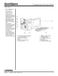
The system board might look slightly different from the one shown.<br />
Note: A diagram of the system board, including switch and jumper settings, is<br />
attached to the underside of the computer cover.
▐1▌Microprocessor ▐13▌Small rocker switch<br />
▐2▌DIMM 0 ▐14▌Battery<br />
▐3▌DIMM 1 ▐15▌Chassis int<strong>ru</strong>sion detection connector<br />
▐4▌Fan connector ▐16▌Wake on LAN connector<br />
▐5▌Power connector ▐17▌Alert on LAN connector<br />
▐6▌Switch/LED connector ▐18▌CD-ROM, CD-RW, or DVD drive connector<br />
▐7▌RFID connector (some models) ▐19▌<strong>PC</strong>I adapter slot 1<br />
▐8▌Primary EIDE connector ▐20▌<strong>PC</strong>I adapter slot 2<br />
▐9▌Secondary EIDE connector ▐21▌<strong>PC</strong>I adapter slot 3 (for Alert on LAN adapter)<br />
▐10▌Diskette drive connector ▐22▌Chassis speaker connector<br />
▐11▌Fan connector ▐23▌AGP adapter slot<br />
▐12▌Large rocker switch (some models)<br />
Rocker switches<br />
The two rocker switches on the system board are used for custom configuration. For<br />
the location of the small and large rocker switches, see items 12 and 13 above.<br />
The large rocker switch has eight switches for setting microprocessor speeds for<br />
compatibility with the system board. The following table shows the rocker switch<br />
settings for compatibility with the corresponding microprocessor speeds.<br />
Chapter 2. System board features 15
16 <strong>PC</strong> 300 GL and 300 PL<br />
Table 6. Large rocker switch settings<br />
Microprocessor<br />
speed<br />
1 2 3 4 5 6 7 8<br />
100<br />
150<br />
200<br />
Off Off On Off Off Off Off Off<br />
133<br />
200<br />
266<br />
133<br />
200<br />
266<br />
166<br />
250<br />
333<br />
200<br />
300<br />
400<br />
233<br />
350<br />
466<br />
266<br />
400<br />
533<br />
300<br />
450<br />
600<br />
333<br />
500<br />
666<br />
366<br />
500<br />
733<br />
400<br />
600<br />
800<br />
433<br />
650<br />
866<br />
On On On On Off Off Off Off<br />
Off Off Off Off Off Off Off Off<br />
On On On Off Off Off Off Off<br />
On On Off On Off Off Off Off<br />
On On Off Off Off Off Off Off<br />
On Off On On Off Off Off Off<br />
On Off On Off Off Off Off Off<br />
On Off Off On Off Off Off Off<br />
On Off Off Off Off Off Off Off<br />
Off On On On Off Off Off Off<br />
Off On On Off Off Off Off Off
Table 6. Large rocker switch settings<br />
Microprocessor<br />
speed<br />
1 2 3 4 5 6 7 8<br />
466<br />
700<br />
933<br />
500<br />
750<br />
1000<br />
533<br />
800<br />
1066<br />
The small rocker switch has three functions. By moving switch 1 to the On position,<br />
you activate the diskette write-protect feature. By moving switch 2 to the On position,<br />
you clear the CMOS. This rocker switch is also used for flash recovery. See the <strong>PC</strong><br />
<strong>300GL</strong> and <strong>PC</strong> 300PL User Guide for inst<strong>ru</strong>ction.<br />
Cable connectors<br />
Connections for attaching devices are provided on the back of the computer. Each<br />
connection has a corresponding device symbol. The connectors are:<br />
• USB (2)<br />
• Mouse<br />
• Keyboard<br />
• Serial (2)<br />
• Parallel<br />
• Monitor<br />
• Ethernet adapter with RJ-45 connector (some models only)<br />
• Integrated audio controller with line in, line out, and microphone connectors<br />
Connector panel<br />
Off On Off On Off Off Off Off<br />
Off On Off Off Off Off Off Off<br />
Off Off On On Off Off Off Off<br />
Reserved Off Off Off On Off Off Off Off<br />
Table 7. Small rocker switch settings<br />
Function On<br />
Diskette write-protect Switch 1<br />
Clear CMOS Switch 2<br />
On the following connector panel illustrations, note the device connection symbols. A<br />
connector provided by an adapter might not have an identifying symbol.<br />
For pin-out details on connectors, see “Appendix A. Connector pin assignments,” on<br />
page 33.<br />
Chapter 2. System board features 17
Serial 2<br />
Mouse<br />
18 <strong>PC</strong> 300 GL and 300 PL<br />
The following illustration shows the connector panel for the desktop model.<br />
2<br />
1<br />
Serial 1<br />
Keyboard<br />
2<br />
1<br />
USB 1 Headphone/<br />
Parallel<br />
USB 2<br />
Line Out<br />
Line In<br />
Microphone<br />
DVI Monitor<br />
SVGA Monitor
Serial 1<br />
Mouse<br />
Keyboard<br />
USB 2<br />
USB 1<br />
Line In<br />
Headphone/<br />
Line Out<br />
Microphone<br />
Parallel<br />
The following illustration shows the connector panel for the tower model.<br />
1<br />
1<br />
Serial 2<br />
2<br />
2<br />
SVGA Monitor<br />
DVI Monitor<br />
Chapter 2. System board features 19
20 <strong>PC</strong> 300 GL and 300 PL
Chapter 3. Physical specifications<br />
<strong>PC</strong> 300 GL and PL desktop<br />
This chapter lists the physical specifications for the <strong>PC</strong> <strong>300GL</strong> personal computer<br />
types <strong>6563</strong>, <strong>6564</strong>, and 6574 and <strong>PC</strong> 300 PL personal computer type 6565. The <strong>PC</strong><br />
<strong>300GL</strong> ad <strong>PC</strong>300PL have four expansion slots and four drive bays.<br />
Note: The <strong>PC</strong> <strong>300GL</strong> and <strong>PC</strong> 300PL computers comply with FCC Class B<br />
specifications.<br />
Dimensions<br />
• Height: 138 mm (5.4 in.)<br />
• Width: 400 mm (15.75 in.)<br />
• Depth: 429 mm (16.9 in.)<br />
Weight<br />
• Minimum configuration as shipped: 9.53 kg (21 lb)<br />
• Maximum configuration: 10.4 kg (23 lb)<br />
Environment<br />
• Air temperature:<br />
— System on: 10° to 35° C (50° to 95° F)<br />
— System off: 10° to 43° C (50° to 110° F)<br />
• Humidity<br />
— System on: 8% to 80%<br />
— System off: 8% to 80%<br />
• Maximum altitude: 2134 m (7000 ft), the maximum altitude at which the<br />
specified air temperatures apply. At higher altitudes, the maximum air<br />
temperatures are lower than those specified.<br />
Electrical input<br />
• Input voltage:<br />
— Low range:<br />
– Minimum: 90 V ac<br />
– Maximum: 137 V ac<br />
– Input frequency range: 57 – 63 Hz<br />
– Voltage switch setting: 115 V ac<br />
— High Range:<br />
– Minimum: 180 V ac<br />
– Maximum: 265 V ac<br />
– Input frequency range: 47 – 53 Hz<br />
– Voltage switch setting: 230 V ac<br />
— Input kilovolt-amperes (kVA) (approximately):<br />
– Minimum configuration as shipped: 0.08 kVA<br />
– Maximum configuration: 0.51 kVA<br />
© Copyright IBM Corp. 2000 21
<strong>PC</strong>300 PL and GL tower<br />
22 <strong>PC</strong> 300 GL and 300 PL<br />
Note: Power consumption and heat output vary depending on the number and<br />
type of optional features installed and the power-management optional<br />
features in use.<br />
Heat output<br />
• Approximate heat output in British thermal units (Btu) per hour:<br />
— Minimum configuration: 256 Btu/hr (75 watts)<br />
— Maximum configuration: 706 Btu/hr (207 watts)<br />
Airflow<br />
• Approximately 0.5 cubic meter per minute (18 cubic feet per minute)<br />
Acoustical noise-emission values<br />
• Average sound-pressure levels:<br />
— At operator position:<br />
– Idle: 33 dBA<br />
– Operating: 39 dBA<br />
— At bystander position-1 meter (3.3 ft):<br />
– Idle: 4.4 bels<br />
– Operating: 4.9 bels<br />
Note: These levels were measures in controlled acoustical environments according<br />
to procedures specified by the American National Standards Institute (ANSI)<br />
S12.10 and ISO 7779, and are reported in accordance with ISO 9296. Actual<br />
sound-pressure levels in your location might exceed the average values stated<br />
because of room reflections and other nearby noise sources. The declared<br />
sound power levels indicate an upper limit, below which a large number of<br />
computers will operate.<br />
Dimensions<br />
• Height: 378 mm (14.9 in.)<br />
• Width: 192 mm (7.6 in.)<br />
• Depth: 383 mm (15.1 in.)<br />
Weight<br />
• Minimum configuration as shipped: 8.3 kg (18.3 lb)<br />
• Maximum configuration: 10.2 kg (22.5 lb)<br />
Environment<br />
• Air temperature:<br />
— System on: 10° to 35°C (50° to 95° F)<br />
— System off: 10° to 43°C (50° to 110° F)<br />
• Humidity<br />
— System on: 8% to 80%<br />
— System off: 8% to 80%<br />
• Maximum altitude: 2134 m (7000 ft), the maximum altitude at which the<br />
specified air temperatures apply. At higher altitudes, the maximum air<br />
temperatures are lower than those specified.<br />
Electrical input<br />
• Input voltage:<br />
— Low range:
– Minimum: 90 V ac<br />
– Maximum: 137 V ac<br />
– Input frequency range: 57 – 63 Hz<br />
– Voltage switch setting: 115 V ac<br />
— High Range:<br />
– Minimum: 180 V ac<br />
– Maximum: 265 V ac<br />
– Input frequency range: 47 – 53 Hz<br />
– Voltage switch setting: 230 V ac<br />
— Input kilovolt-amperes (kVA) (approximately):<br />
– Minimum configuration as shipped: 0.08 kVA<br />
– Maximum configuration: 0.51 kVA<br />
Note: Power consumption and heat output vary depending on the number and<br />
type of optional features installed and the power-management optional<br />
features in use.<br />
Heat output<br />
• Approximate heat output in British thermal units (Btu) per hour:<br />
— Minimum configuration: 256 Btu/hr (75 watts)<br />
— Maximum configuration: 706 Btu/hr (207 watts)<br />
Airflow<br />
• Approximately 0.5 cubic meter per minute (18 cubic feet per minute)<br />
Acoustical noise-emission values<br />
• Average sound-pressure levels:<br />
— At operator position:<br />
– Idle: 33 dBA<br />
– Operating: 40 dBA<br />
— At bystander position-1 meter (3.3 ft):<br />
– Idle: 4.4 bels<br />
– Operating: 4.9 bels<br />
Note: These levels were measures in controlled acoustical environments according<br />
to procedures specified by the American National Standards Institute (ANSI)<br />
S12.10 and ISO 7779, and are reported in accordance with ISO 9296. Actual<br />
sound-pressure levels in your location might exceed the average values stated<br />
because of room reflections and other nearby noise sources. The declared<br />
sound power levels indicate an upper limit, below which a large number of<br />
computers will operate.<br />
Chapter 3. Physical specifications 23
24 <strong>PC</strong> 300 GL and 300 PL
Chapter 4. Power supply<br />
Power input<br />
Power output<br />
A 145-watt power supply drives your computer. The power supply provides 3.3-volt<br />
power for the Pentium III microprocessor, core chip set, and 5-volt power for <strong>PC</strong>I<br />
adapters. Also included is an auxiliary 5-volt (AUX 5) power supply to provide<br />
power to power-management circuitry and a Wake on LAN adapter. The power<br />
supply converts the ac input voltage into four dc output voltages and provides power<br />
for the following:<br />
• System board<br />
• Adapters<br />
• Internal drives<br />
• Keyboard and auxiliary devices<br />
• USB devices<br />
A logic signal on the power connector controls the power supply; the front panel<br />
switch is not directly connected to the power supply.<br />
The power supply connects to the system board with a 2 x 10 pin connector.<br />
The following table shows the power input specifications. The power supply has a<br />
manual switch to select the correct input voltage.<br />
Table 8. Power input requirements<br />
Specification Measurements<br />
Input voltage, low range 100 (min) to 127 (max) V ac<br />
Input voltage, high range 200 (min) to 240 (max) V ac<br />
Input frequency 50 Hz ± 3 Hz or 60 Hz ± 3 Hz<br />
The following figures show the power supply output of all the connectors, including<br />
the system board, DASD, <strong>PC</strong>I, and auxiliary outputs.<br />
Table 9. Power output (145 watts)<br />
Output voltage Tolerance Minimum current Maximum current<br />
+5 V dc +5% to -5% 1.5 A 18.0 A<br />
+12 V dc +5% to -5% 0.02 A 4.2 A<br />
-12 V dc +10% to -10% 0.0 A 0.4 A<br />
+3.3 V dc +5% to -5% 0.0 A 10.0 A<br />
+5 V ac (auxiliary) +5% to -5% 0.0 A 0.720 A<br />
The total combined 3.3 V and 5 V power must not exceed 100 watts.<br />
© Copyright IBM Corp. 2000 25
Component outputs<br />
26 <strong>PC</strong> 300 GL and 300 PL<br />
The power supply provides separate voltage sources for the system board and<br />
internal storage devices. The following figures show the approximate power that is<br />
provided for specific system components. Many components draw less current than<br />
the maximum shown.<br />
Table 10. System board<br />
Supply voltage Maximum current Tolerance<br />
+3.3 V dc 5000 mA +5.0% to -5.0%<br />
+5.0 V dc 6000 mA +5.0 to -4.0%<br />
+12.0 V dc 25.0 mA +5.0% to -5.0%<br />
-12.0 V dc 25.0 mA +10.0% to -9.0%<br />
Table 11. Keyboard port<br />
Supply voltage Maximum current Tolerance<br />
+5.0 V dc 275 mA +5.0% to -4.0%<br />
Table 12. Auxiliary device port<br />
Supply voltage Maximum current Tolerance<br />
+5.0 V dc 300 mA +5.0% to -4.0%<br />
Table 13. <strong>PC</strong>I-bus adapters (per slot)<br />
Supply voltage Maximum current Tolerance<br />
+5.0 V dc 1000 mA +5.0% to -4.0%<br />
+3.3 V dc 1500 mA +5.0% to -4.0%<br />
Note: For each <strong>PC</strong>I connector, the maximum power consumption is rated at 5 watts<br />
for +5 V dc and +3.3 V dc combined. If maximum power is used, the overall<br />
system configuration will be limited in performance.<br />
Table 14. USB port<br />
Supply voltage Maximum current Tolerance<br />
+5.0 V dc 500 mA +5.0%to -4.0%<br />
Table 15. Internal DASD<br />
Supply voltage Maximum current Tolerance<br />
+5.0 V dc 1400 mA +5.0% to -5.0%
Output protection<br />
Connector description<br />
Table 15. Internal DASD<br />
Supply voltage Maximum current Tolerance<br />
+12.0 V dc 1500 mA at startup, 400 mA<br />
when active<br />
+5.0% to -5.0%<br />
Table 16. Video port pin 9<br />
Supply voltage Maximum current Tolerance<br />
+5.0 V dc 1100 mA +5.0% to -5.0%<br />
Note: Some adapters and hard disk drives draw more current than the rated<br />
maximums. These adapters and drives can be installed in the system;<br />
however, the power supply will shut down if the total power used exceeds<br />
the maximum power that is available.<br />
The power supply protects against output overcurrent, overvoltage, and short<br />
circuits. See the power supply specifications on the previous pages for details.<br />
A short circuit that is placed on any dc output (between outputs or between an output<br />
and a dc return) latches all dc outputs into a shutdown state, with no damage to the<br />
power supply. If this shutdown state occurs, the power supply returns to normal<br />
operation only after the fault has been removed and the power switch has been<br />
turned off for at least one second.<br />
If an overvoltage fault occurs (in the power supply), the power supply latches all dc<br />
outputs into a shutdown state before any output exceeds 130% of the power supply<br />
value.<br />
The power supply for <strong>PC</strong> <strong>300GL</strong> and <strong>PC</strong> 300PL personal computers has four, 4-pin<br />
connectors for internal devices. The total power used by the connectors must not<br />
exceed the amount shown in “Component outputs” on page 26. For connector pin<br />
assignments, see “Appendix A. Connector pin assignments,” on page 33.<br />
Chapter 4. Power supply 27
28 <strong>PC</strong> 300 GL and 300 PL
Chapter 5. System software<br />
BIOS<br />
Plug and Play<br />
POST<br />
This section briefly describes some of the system software included with your<br />
computer.<br />
Your personal computer uses the IBM basic input/output system (BIOS), which is<br />
stored in flash electrically erasable programmable read-only memory (EEPROM).<br />
Some features of the BIOS are:<br />
• <strong>PC</strong>I support according to <strong>PC</strong>I BIOS Specification 2.2<br />
• Microsoft <strong>PC</strong>I IRQ Routing Table<br />
• Plug and Play support according to Plug and Play BIOS Specification 1.1a<br />
• Advanced Power Management (APM) support according to APM BIOS Interface<br />
Specification 1.2<br />
• Wake on LAN support<br />
• Wake on Ring support<br />
• Remote Initial Program Load (RIPL) and Dynamic Host Configuration Protocol<br />
(DHCP)<br />
• Flash-over-LAN support<br />
• Alternate startup sequence<br />
• IBM Look and Feel - such as screen arrangements and user interface<br />
• ACPI (Advanced Configuration and Power Interface)<br />
• IDE Logical Block Addressing (LBA)<br />
• LSA 2.0 support<br />
• Digital optical disk support<br />
• LS-120 disk drive support<br />
• DM BIOS 2.1 (DMI 2.0 compliant)<br />
• <strong>PC</strong>99 compliance<br />
Support for Plug and Play conforms to the following:<br />
• Plug and Play BIOS Specification 1.1a and 1.0<br />
• Plug and Play BIOS Extension Design Guide<br />
• Plug and PLay BIOS Specification, Errata, and Clarifications 1.0<br />
• Guide to Integrating the Plug and Play BIOS Extensions with system BIOS 1.2<br />
• Plug and Play Kit for DOS and Windows<br />
IBM power-on self-test (POST) code is used. Also, initialization code is included for<br />
the on-board system devices and controllers.<br />
POST error codes include text messages for determining the cause of an error. For<br />
more information, see “Appendix D. Error codes,” on page 55 and your <strong>PC</strong> <strong>300GL</strong> and<br />
<strong>PC</strong> 300PL User Guide.<br />
© Copyright IBM Corp. 2000 29
Configuration/Setup Utility program<br />
30 <strong>PC</strong> 300 GL and 300 PL<br />
The Configuration/Setup Utility program provides menu choices for devices, I/O<br />
ports, date and time, system security, start options, advanced setup, and power<br />
management.<br />
More detailed information on using the Configuration/Setup Utility program is in the<br />
<strong>PC</strong> <strong>300GL</strong> and <strong>PC</strong> 300PL User Guide.<br />
Advanced Power Management (APM)<br />
The <strong>PC</strong> <strong>300GL</strong> computers have built-in energy-saving capabilities. Advanced Power<br />
Management (APM) is a feature that reduces the power consumption of components<br />
when they are not in use. When enabled, APM initiates reduced-power modes for the<br />
monitor, microprocessor, and hard disk drive after a specified period of inactivity.<br />
The BIOS supports APM 1.2. This enables the system to enter a power-management<br />
state, reducing the power drawn from the AC electrical outlet. Advanced Power<br />
Management is enabled through the Configuration/Setup Utility program and is<br />
controlled by the individual operating system.<br />
For more information on APM, see the <strong>PC</strong> <strong>300GL</strong> and <strong>PC</strong> 300PL User Guide and<br />
Understanding Your Personal Computer.<br />
Advanced Configuration and Power Interface (ACPI)<br />
Flash update utility program<br />
Diagnostic program<br />
Advanced Configuration and Power Interface (ACPI) BIOS mode enables the<br />
operating system to control the power-management features of your computer. Not<br />
all operating systems support ACPI BIOS mode. Refer to your operating-system<br />
documentation to determine if ACPI is supported.<br />
The flash update utility program is a stand-alone program to support flash updates.<br />
This utility program updates the BIOS code and the machine readable information<br />
(MRI) to different languages.<br />
The latest version of the flash update utility program is available on the IBM Web site<br />
at http://www.ibm.com/pc/support and can be copied to a 3.5-inch diskette.<br />
The diagnostic program that comes with <strong>PC</strong> 300PL and the <strong>PC</strong> <strong>300GL</strong> personal<br />
computers is provided as a startable IBM Enhanced Diagnostic diskette image on the<br />
IBM Product Recovery CD or the Device Driver and IBM Enhanced Diagnostic CD. It <strong>ru</strong>ns<br />
independently of the operating system. The user interface is WaterGate Software <strong>PC</strong>-<br />
Doctor. The diagnostic program can also be downloaded from the following World<br />
Wide Web page: http://www.ibm.com/pc/support/. For more information on the<br />
diagnostic program, see the <strong>PC</strong> <strong>300GL</strong> and <strong>PC</strong> 300PL User Guide.
Chapter 6. System compatibility<br />
Hardware compatibility<br />
This chapter discusses some of the hardware, software, and BIOS compatibility issues<br />
for the computer. See the Compatibility Report under, “Related publications” on page<br />
vii for a list of compatible hardware and software options.<br />
This section discusses hardware, software, and BIOS compatibility that must be<br />
considered when designing application programs.<br />
The functional interfaces are compatible with the following interfaces:<br />
• Intel 8259 inter<strong>ru</strong>pt controllers (edge-triggered mode)<br />
• National Semiconductor NS16450 and NS126550A serial communications<br />
controllers<br />
• Motorola MC146818 Time of Day Clock command and status (CMOS<br />
reorganized)<br />
• Intel 8254 timer, driven from a 1.193 MHz clock (channels 0, 1, and 2)<br />
• Intel 8237 DMA controller, except for the Command and Request registers and<br />
the Rotate and Mask functions; the Mode register is partially supported<br />
• Intel 8272 or 82077 diskette drive controllers<br />
• Intel 8042 keyboard controller at address hex 0060 and hex 0064<br />
• All video standards using VGA, EGA, CGA, MDA, and Hercules modes<br />
• Parallel printer ports (Parallel 1, Parallel 2, and Parallel 3) in compatibility mode<br />
Use this information to develop application programs. Whenever possible, use the<br />
BIOS as an interface to hardware to provide maximum compatibility and portability<br />
of applications among systems.<br />
Hardware inter<strong>ru</strong>pts<br />
Hardware inter<strong>ru</strong>pts are level-sensitive for <strong>PC</strong>I inter<strong>ru</strong>pts. The inter<strong>ru</strong>pt controller<br />
clears its in-service register bit when the inter<strong>ru</strong>pt routine sends and End-of-Inter<strong>ru</strong>pt<br />
(EOI) command to the controller. The EOI command is sent regardless of whether the<br />
incoming inter<strong>ru</strong>pt request to the controller is active or inactive.<br />
The inter<strong>ru</strong>pt-in-progress latch is readable at an I/O-address bit position. This latch is<br />
read during the inter<strong>ru</strong>pt service routine and might be reset by the read operation or it<br />
might require an explicit reset.<br />
Note: For performance and latency considerations, designers might want to limit<br />
the number of devices sharing an inter<strong>ru</strong>pt level.<br />
With level-sensitive inter<strong>ru</strong>pts, the inter<strong>ru</strong>pt controller requires that the inter<strong>ru</strong>pt<br />
request be inactive at the time the EOI command is sent; otherwise, a new inter<strong>ru</strong>pt<br />
request will be detected. To avoid this, a level-sensitive inter<strong>ru</strong>pt handler must clear<br />
the inter<strong>ru</strong>pt condition (usually by a read or write operation to an I/O port on the<br />
device causing the inter<strong>ru</strong>pt). After processing the inter<strong>ru</strong>pt, the inter<strong>ru</strong>pt handler:<br />
1. Clears the inter<strong>ru</strong>pt<br />
2. Waits one I/O delay<br />
© Copyright IBM Corp. 2000 31
Software compatibility<br />
32 <strong>PC</strong> 300 GL and 300 PL<br />
3. Sends the EOI<br />
4. Waits one I/O delay<br />
5. Enables the inter<strong>ru</strong>pt through the Set Inter<strong>ru</strong>pt Enable Flag command<br />
Hardware inter<strong>ru</strong>pt IRQ9 is defined as the replacement inter<strong>ru</strong>pt level for the cascade<br />
level IRQ2. Program inter<strong>ru</strong>pt sharing is implemented on IRQ2, inter<strong>ru</strong>pt hex 0A.<br />
The following processing occurs to maintain compatibility with the IRQ2 used by IBM<br />
Personal Computer products:<br />
1. A device drives the inter<strong>ru</strong>pt request active on IRQ2 of the channel.<br />
2. This inter<strong>ru</strong>pt request is mapped in hardware to IRQ9 input on the second<br />
inter<strong>ru</strong>pt controller.<br />
3. When the inter<strong>ru</strong>pt occurs, the system microprocessor passes control to the IRQ9<br />
(inter<strong>ru</strong>pt hex 71) inter<strong>ru</strong>pt handler.<br />
4. This inter<strong>ru</strong>pt handler performs an EOI command to the second inter<strong>ru</strong>pt<br />
controller and passes control to the IRQ2 (inter<strong>ru</strong>pt hex 0A) inter<strong>ru</strong>pt handler.<br />
5. This IRQ2 inter<strong>ru</strong>pt handler, when handling the inter<strong>ru</strong>pt, causes the device to<br />
reset the inter<strong>ru</strong>pt request before performing an EOI command to the master<br />
inter<strong>ru</strong>pt controller that finishes servicing the IRQ2 request.<br />
To maintain software compatibility, the inter<strong>ru</strong>pt polling mechanism that is used by<br />
IBM Personal Computer products is retained. Software that interfaces with the reset<br />
port for the IBM Personal Computer positive-edge inter<strong>ru</strong>pt sharing (hex address<br />
02Fx or 06Fx, where x is the inter<strong>ru</strong>pt level) does not create interference.<br />
Software inter<strong>ru</strong>pts<br />
With the advent of software inter<strong>ru</strong>pt sharing, software inter<strong>ru</strong>pt routines must daisy<br />
chain inter<strong>ru</strong>pts. Each routine must check the function value, and if the function<br />
value is not in the range of function calls, that routine must transfer control to the next<br />
routine in the chain. Because software inter<strong>ru</strong>pts are initially pointed to address 0:0<br />
before daisy chaining, check for this case. If the next routine is pointed to address 0:0<br />
and the function call is out of range, the appropriate action is to set the carry flag and<br />
initiate a RET 2 to indicate an error condition.<br />
Machine-sensitive programs<br />
Programs can select machine-specific features, but they must first identify the<br />
machine and model type. IBM has defined methods for uniquely determining the<br />
specific machine type. The machine model byte can be found through inter<strong>ru</strong>pt 15H,<br />
Return System Configuration Parameters function (AH)=(C0H).
Appendix A. Connector pin assignments<br />
SVGA monitor connector<br />
The following figures show the pin assignments for various system board connectors.<br />
5 1<br />
10 6<br />
15 11<br />
Table 17. SVGA monitor port connector pin assignments<br />
Pin Signal I/O Pin Signal I/O<br />
1 Red O 9 +5 V, used by<br />
DDC2B<br />
NA<br />
2 Green O 10 Ground NA<br />
3 Blue O 11 Monitor ID 0 -<br />
Not used<br />
I<br />
4 Monitor ID 2 - I 12 DDC2B serial I/O<br />
Not used<br />
data<br />
5 Ground NA 13 Horizontal<br />
sync<br />
O<br />
6 Red ground NA 14 Vertical sync O<br />
7 Green ground NA 15 DDC2B clock I/O<br />
8 Blue ground NA<br />
© Copyright IBM Corp. 2000 33
DVI-I monitor connector<br />
Table 18. DVI-I monitor port connector pin assignments - main pin field<br />
Pin Signal Pin Signal<br />
1 TMDS data 2+ 13 TMDS data 3+<br />
2 TMDS data 2- 14 +5V power<br />
3 TMDS data 2/4 return 15 Ground<br />
4 TMDS data 4- 16 Hot plug detect<br />
5 TMDS data 4+ 17 TMDS data 0-<br />
6 DDC clock 18 TMDS data 0+<br />
7 DDC data 19 TMDS data 0-<br />
8 Analog vertical sync 20 TMDS data 0/5 shield<br />
9 TMDS data 1- 21 TMDS data 5+<br />
10 TMDS data 1+ 22 TMDS clock shield<br />
11 TMDS 1/3 shield 23 TMDS clock+<br />
12 TMDS data 3+ 24 TMDS clock-<br />
Table 19. DVI connector pin assignments - micro cross section<br />
Pin Signal<br />
C1 Red video out<br />
C2 Green video out<br />
C3 Analog blue<br />
C4 Analog horizontal sync<br />
C5 Video/pixel clock return<br />
System memory connector<br />
34 <strong>PC</strong> 300 GL and 300 PL<br />
85<br />
1<br />
1 C1 C2<br />
C3<br />
C4<br />
C5<br />
168<br />
84
Table 20. System memory connector pin assignments<br />
Pin x64 nonparity x72 ECC Pin x64 nonparity x72 ECC<br />
1 VSS VSS 85 VSS VSS<br />
2 DQ0 DQ0 86 DQ32 DQ32<br />
3 DQ1 DQ1 87 DQ33 DQ33<br />
4 DQ2 DQ2 88 DQ34 DQ34<br />
5 DQ3 DQ3 89 DQ35 DQ35<br />
6 VCC VCC 90 VCC VCC<br />
7 DQ4 DQ4 91 DQ36 DQ36<br />
8 DQ5 DQ5 92 DQ37 DQ37<br />
9 DQ6 DQ6 93 DQ38 DQ38<br />
10 DQ7 DQ7 94 DQ39 DQ39<br />
11 DQ8 DQ8 95 DQ40 DQ40<br />
12 VSS VSS 96 VSS VSS<br />
13 DQ9 DQ 97 DQ41 DQ41<br />
14 DQ10 DQ10 98 DQ42 DQ42<br />
15 DQ11 DQ11 99 DQ43 DQ43<br />
16 DQ12 DQ12 100 DQ44 DQ44<br />
17 DQ13 DQ13 101 DQ45 DQ45<br />
18 VCC VCC 102 VCC VCC<br />
19 DQ14 DQ14 103 DQ46 DQ46<br />
20 DQ15 DQ15 104 DQ47 DQ47<br />
21 NC CB0 105 NC CB4<br />
22 NC CB1 106 NC CB5<br />
23 VSS VSS 107 VSS VSS<br />
24 NC NC 108 NC NC<br />
25 NC NC 109 NC NC<br />
26 VCC VCC 110 VCC VCC<br />
27 /WE /WE0 111 /CAS /CAS<br />
28 DQMB0 DQMB0 112 DQMB4 DQMB4<br />
29 DQMB1 DQMB1 113 DQMB5 DQMB5<br />
30 /S0 /S0 114 NC /S1<br />
31 DU NC 115 /RAS /RAS<br />
32 VSS VSS 116 VSS VSS<br />
33 A0 A0 117 A1 A1<br />
34 A2 A2 118 A3 A3<br />
35 A4 A4 119 A5 A5<br />
Appendix A. Connector pin assignments 35
Table 20. System memory connector pin assignments<br />
Pin x64 nonparity x72 ECC Pin x64 nonparity x72 ECC<br />
36 A6 A6 120 A7 A7<br />
37 A8 A8 121 A9 A9<br />
38 A10/AP A10/AP 122 BA0 BA0<br />
39 NC BA1 123 NC A11<br />
40 VCC VCC 124 VCC VCC<br />
41 VCC VCC 125 CK1 CK1<br />
42 CK0 CK0 126 A12 A12<br />
43 VSS VSS 127 VSS VSS<br />
44 DU NC 128 CKE0 CKE0<br />
45 /S2 /S2 129 NC /S3<br />
46 DQMB2 DQMB2 130 DQMB6 DQMB6<br />
47 DQMB3 DQMB3 131 DQMB7 DQMB7<br />
48 DU NC 132 A13 A13<br />
49 VCC VCC 133 VCC VCC<br />
50 NC NC 134 NC NC<br />
51 NC NC 135 NC NC<br />
52 NC CB2 136 NC CB6<br />
53 NC CB3 137 NC CB7<br />
54 VSS VSS 138 VSS VSS<br />
55 DQ16 DQ16 139 DQ48 DQ48<br />
56 DQ17 DQ17 140 DQ49 DQ49<br />
57 DQ18 DQ18 141 DQ50 DQ50<br />
58 DQ19 DQ19 142 DQ51 DQ51<br />
59 VCC VCC 143 VCC VCC<br />
60 DQ20 DQ20 144 DQ52 DQ52<br />
61 NC NC 145 NC NC<br />
62 NC NC 146 NC NC<br />
63 NC CKE1 147 NC NC<br />
64 VSS VSS 148 VSS VSS<br />
65 DQ21 DQ21 149 DQ53 DQ53<br />
66 DQ22 DQ22 150 DQ54 DQ54<br />
67 DQ23 DQ23 151 DQ55 DQ55<br />
68 VSS VSS 152 VSS VSS<br />
69 DQ24 DQ24 153 DQ56 DQ56<br />
70 DQ25 DQ25 154 DQ57 DQ57<br />
36 <strong>PC</strong> 300 GL and 300 PL
Table 20. System memory connector pin assignments<br />
Pin x64 nonparity x72 ECC Pin x64 nonparity x72 ECC<br />
71 DQ26 DQ26 155 DQ58 DQ58<br />
72 DQ27 DQ27 156 DQ59 DQ59<br />
73 VCC VCC 157 VCC VCC<br />
74 DQ28 DQ28 158 DQ60 DQ60<br />
75 DQ29 DQ29 159 DQ61 DQ61<br />
76 DQ30 DQ30 160 DQ62 DQ62<br />
77 DQ31 DQ31 161 DQ63 DQ63<br />
78 VSS VSS 162 VSS VSS<br />
79 CK2 CK2 163 CK3 CK3<br />
80 NC NC 164 NC NC<br />
81 NC NC 165 SA0 SA0<br />
82 SKA SDA 166 SA1 SA1<br />
83 SCL SCL 167 SA2 SA2<br />
84 VCC VCC 168 VCC VCC<br />
Table 21. System memory connector pin input/output<br />
Pin Signal name I/O Pin Signal name I/O<br />
1 GND N/A 85 GND N/A<br />
2 MD0 I/O 86 MD32 I/O<br />
3 MD1 I/O 87 MD33 I/O<br />
4 MD2 I/O 88 MD34 I/O<br />
5 MD3 I/O 89 MD35 I/O<br />
6 VDD I/O 90 VDD N/A<br />
7 MD4 I/O 91 MD36 N/A<br />
8 MD5 I/O 92 MD37 I/O<br />
9 MD6 I/O 93 MD38 I/O<br />
10 MD7 I/O 94 MD39 I/O<br />
11 MD8 (PAR0) I/O 95 MD40 I/O<br />
12 GND N/A 96 GND N/A<br />
13 MD9 I/O 97 MD41 I/O<br />
14 MD10 I/O 98 MD42 I/O<br />
15 MD11 I/O 99 MD43 I/O<br />
16 MD12 I/O 100 MD44 I/O<br />
17 MD13 I/O 101 MD45 I/O<br />
18 VDD N/A 102 VDD N/A<br />
Appendix A. Connector pin assignments 37
Table 21. System memory connector pin input/output<br />
Pin Signal name I/O Pin Signal name I/O<br />
19 MD14 I/O 103 MD46 I/O<br />
20 MD15 I/O 104 MD47 I/O<br />
21 NC I/O 105 NC I/O<br />
22 NC I/O 106 NC I/O<br />
23 GND I/O 107 GND N/A<br />
24 NC N/A 108 NC N/A<br />
25 NC N/A 109 NC N/A<br />
26 VDD N/A 110 VDD N/A<br />
27 WE# I 111 CAS# N/A<br />
28 DQMB0# I 112 DQMB4# I<br />
29 DQMB1# I 113 DQMB4# I<br />
30 S0# I 114 S1# I<br />
31 OE0# I 115 RAS# N/A<br />
32 GND N/A 116 GND N/A<br />
33 A0 I 117 A1 I<br />
34 A2 I 118 A3 I<br />
35 A4 I 119 A5 I<br />
36 A6 I 120 A7 I<br />
37 A8 I 121 A9 I<br />
38 A10/AP I 122 A11 I<br />
39 NC 123 NC<br />
40 VDD N/A 124 VDD N/A<br />
41 NC N/A 125 CK1 N/A<br />
42 CK0 N/A 126 A14 O<br />
43 GND N/A 127 GND N/A<br />
44 OE2# I 128 CKE0 N/A<br />
45 S2# I 129 S3# I<br />
46 DQMB2# I 130 DQMB6# I<br />
47 DQMB3# I 131 DQMB7# I<br />
48 WE2# I 132 A15 I<br />
49 VDD N/A 133 VDD N/A<br />
50 NC N/A 134 NC N/A<br />
51 NC N/A 135 NC N/A<br />
52 NC I/O 136 NC I/O<br />
53 NC I/O 137 NC I/O<br />
38 <strong>PC</strong> 300 GL and 300 PL
Table 21. System memory connector pin input/output<br />
Pin Signal name I/O Pin Signal name I/O<br />
54 GND N/A 138 GND N/A<br />
55 MD16 I/O 139 MD48 I/O<br />
56 MD17 I/O 140 MD49 I/O<br />
57 MD18 I/O 141 MD50 I/O<br />
58 MD19 I/O 142 MD51 I/O<br />
59 VDD N/A 143 VDD N/A<br />
60 MD20 I/O 144 MD52 I/O<br />
61 CKE1 N/A 145 NC N/A<br />
62 VREF N/A 146 VREF N/A<br />
63 (CKE1)* N/A 147 NC N/A<br />
64 GND N/A 148 GND N/A<br />
65 MD21 I/O 149 MD53 I/O<br />
66 MD22 I/O 150 MD54 I/O<br />
67 MD23 I/O 151 MD55 I/O<br />
68 GND N/A 152 GND N/A<br />
69 MD24 I/O 153 MD56 I/O<br />
70 MD25 I/O 154 MD57 I/O<br />
71 MD26 I/O 155 MD58 I/O<br />
72 MD27 I/O 156 MD59 I/O<br />
73 VDD N/A 157 VDD N/A<br />
74 MD28 I/O 158 MD60 I/O<br />
75 MD29 I/O 159 MD61 I/O<br />
76 MD30 I/O 160 MD62 I/O<br />
77 MD31 I/O 161 MD63 I/O<br />
78 GND N/A 162 GND N/A<br />
79 CK2 O 163 CK3 O<br />
80 NC N/A 164 NC N/A<br />
81 NC O 165 SA0 O<br />
82 SDA O 166 SA1 O<br />
83 SCL O 167 SA0 O<br />
84 VDD N/A 168 VDD N/A<br />
Appendix A. Connector pin assignments 39
<strong>PC</strong>I connectors<br />
Table 22. <strong>PC</strong>I connector pin assignments<br />
Pin Signal I/O Pin Signal I/O<br />
A1 TRST# O B1 -12 V dc N/A<br />
A2 +12 V dc N/A B2 TCK O<br />
A3 +12 V dc O B3 Ground N/A<br />
A4 TDI O B4 TDO I<br />
A5 +5 V dc N/A B5 +5 V dc N/A<br />
A6 INTA# I B6 +5 V dc N/A<br />
A7 INTC# I B7 INTB# I<br />
A8 +5 V dc N/A B8 INTD# I<br />
A9 Reserved N/A B9 PRSNT1# I<br />
A10 +5 V dc (I/O) N/A B10 Reserved N/A<br />
A11 Reserved N/A B11 PRNST2 I<br />
A12 Ground N/A B12 Ground N/A<br />
A13 Ground N/A B13 Ground N/A<br />
A14 Reserved N/A B14 Reserved N/A<br />
A15 RST# O B15 Ground N/A<br />
A16 +5 V dc (I/O) N/A B16 O O<br />
A17 GNT# O B17 Ground N/A<br />
A18 Ground N/A B18 REQ# I<br />
A19 <strong>PC</strong>IPME N/A B19 +5 V dc (I/O) N/A<br />
A20 Address/data 30 I/O B20 Address/data 31 I/O<br />
A21 +3.3 V dc N/A B21 Address/data 29 I/O<br />
A22 Address/data 28 I/O B22 Ground N/A<br />
A23 Address/data 26 I/O B23 Address/data 27 I/O<br />
A24 Ground I/O B24 Address/data 25 N/A<br />
A25 Address/data 24 I/O B25 +3.3 V dc N/A<br />
A26 IDSEL O B26 C/BE 3# I/O<br />
A27 +3.3 V dc N/A B27 Address/data 23 I/O<br />
40 <strong>PC</strong> 300 GL and 300 PL<br />
A2<br />
A1<br />
B1<br />
B2<br />
A62<br />
B62
Table 22. <strong>PC</strong>I connector pin assignments<br />
Pin Signal I/O Pin Signal I/O<br />
A28 Address/data 22 I/O B28 Ground N/A<br />
A29 Address/data 20 I/O B29 Address/data 21 I/O<br />
A30 Ground I/O B30 Address/data 19 N/A<br />
A31 Address/data 18 I/O B31 +3.3 V dc N/A<br />
A32 Address/data 16 I/O B32 Address/data 17 I/O<br />
A33 +3.3 V dc N/A B33 C/BE2# I/O<br />
A34 FRAME# I/O B34 Ground N/A<br />
A35 Ground N/A B35 IRDY# I/O<br />
A36 TRDY# I/O B36 +3.3 V dc N/A<br />
A37 Ground N/A B37 DEVSEL# I/O<br />
A38 STOP# I/O B38 Ground N/A<br />
A39 +3.3 V dc N/A B39 LOCK# I/O<br />
A40 SDONE I/O B40 PERR# I/O<br />
A41 SBO# I/O B41 +3.3 V dc N/A<br />
A42 Ground N/A B42 SERR# I/O<br />
A43 +3.3 V dc N/A B43 +3.3 V dc N/A<br />
A44 C/BE(1)# I/O B44 C/BE 1# I/O<br />
A45 Address/data 14 I/O B45 Address/data 14 I/O<br />
A46 Ground N/A B46 Ground N/A<br />
A47 Address/data 12 I/O B47 Address/data 12 I/O<br />
A48 Address/data 10 I/O B48 Address/data 10 I/O<br />
A49 Ground N/A B49 Ground N/A<br />
A50 Key N/A B50 Key N/A<br />
A51 Key N/A B51 Key N/A<br />
A52 Address/data 8 I/O B52 Address/data 8 I/O<br />
A53 Address/data 7 I/O B53 Address/data 7 I/O<br />
A54 +3.3 V dc N/A B54 +3.3 V dc N/A<br />
A55 Address/data 5 I/O B55 Address/data 5 I/O<br />
A56 Address/data 3 I/O B56 Address/data 3 I/O<br />
A57 Ground N/A B57 Ground N/A<br />
A58 Address/data 1 I/O B58 Address/data 1 I/O<br />
A59 +5 V dc (I/O) N/A B59 +5 V dc (I/O) N/A<br />
A60 ACK64# I/O B60 ACK64# I/O<br />
A61 +5 V dc N/A B61 +5 V dc N/A<br />
A62 +5 V dc N/A A62 +5 V dc N/A<br />
Appendix A. Connector pin assignments 41
IDE connectors<br />
Table 23. IDE connector pin assignments<br />
Pin Signal I/O Pin Signal I/O<br />
1 RESET O 21 NC N/A<br />
2 Ground N/A 22 Ground N/A<br />
3 Data bus bit 7 I/O 23 I/O write O<br />
4 Data bus bit 8 I/O 24 NC N/A<br />
5 Data bus bit 6 I/O 25 I/O read O<br />
6 Data bus bit 9 I/O 26 Ground I<br />
7 Data bus bit 5 I/O 27 I/O channel ready I<br />
8 Data bus bit 10 I/O 28 ALE O<br />
9 Data bus bit 4 I/O 29 NC N/A<br />
10 Data bus bit 11 I/O 30 Ground N/A<br />
11 Data bus bit 3 I/O 31 IRQ I<br />
12 Data bus bit 12 I/O 32 CS16# I<br />
13 Data bus bit 2 I/O 33 SA1 O<br />
14 Data bus bit 13 I/O 34 PDIAG# I<br />
15 Data bus bit 1 I/O 35 SA0 O<br />
16 Data bus bit 14 I/O 36 SA2 O<br />
17 Data bus bit 0 I/O 37 CS0# O<br />
18 Data bus bit 15 I/O 38 CS1 O<br />
19 Ground N/A 39 Active# I<br />
20 Key (Reserved) N/A 40 Ground N/A<br />
42 <strong>PC</strong> 300 GL and 300 PL<br />
2 40<br />
1<br />
39
Diskette drive connector<br />
2 34<br />
1<br />
Table 24. Diskette drive connector pin assignments<br />
Pin Signal I/O Pin Signal I/O<br />
1 Drive 2 installed # I 18 Direction in# O<br />
2 High density<br />
select<br />
O 19 Ground N/A<br />
3 Not connected N/A 20 Step# O<br />
4 Not connected N/A 21 Ground N/A<br />
5 Ground N/A 22 Write data # O<br />
6 Data rate 0 N/A 23 Ground N/A<br />
7 Ground N/A 24 Write enable# O<br />
8 Index# I 25 Ground N/A<br />
9 Reserved N/A 26 Track0# I<br />
10 Motor enable 0# O 27 MSEN0 I<br />
11 Ground N/A 28 Write protect# I<br />
12 Drive select 1# O 29 Ground N/A<br />
13 Ground N/A 30 Read data# I<br />
14 Drive select 0# O 31 Ground N/A<br />
15 Ground N/A 32 Head 1 select# O<br />
16 Motor enable 1# O 33 Data rate 1 N/A<br />
17 MSEN1 I 34 Diskette change# I<br />
33<br />
Appendix A. Connector pin assignments 43
Power supply connector<br />
Table 25. Power supply connector pin assignments<br />
Pin Signal Function Pin Signal Function<br />
1 3.3 V dc +3.3 V dc 11 3.3 V dc +3.3 V dc<br />
2 3.3 V dc +3.3 V dc 12 -12 V dc -12 V dc<br />
3 COM Ground 13 COM Ground<br />
4 5 V dc +5 V dc 14 PS-ON DC Remote<br />
Enable<br />
5 COM Ground 15 COM Ground<br />
6 5 V dc +5 V dc 16 COM Ground<br />
7 COM Ground 17 COM Ground<br />
8 POK PWR GOOD 18 Reserved Reserved<br />
9 5 VSB Standby Voltage 19 5 V dc +5 V dc<br />
10 12 V dc +12 V dc 20 5 V dc +5 V dc<br />
Wake on LAN connectors<br />
Table 26. J14 Wake on LAN connector pin assignments<br />
Pin Description<br />
1 +5 V AUX<br />
2 Ground<br />
3 Internal Wake on LAN<br />
USB port connectors<br />
Table 27. USB port connector pin assignments<br />
Pin Signal<br />
1 VCC<br />
2 -Data<br />
3 +Data<br />
4 Ground<br />
44 <strong>PC</strong> 300 GL and 300 PL<br />
1<br />
3<br />
2<br />
4
Mouse and keyboard port connectors<br />
Table 28. Mouse port connector pin assignments<br />
Pin Signal I/O Pin Signal I/O<br />
1 Data I/O 4 +5 V dc N/A<br />
2 Reserved I/O 5 Clock I/O<br />
3 Ground N/A 6 Reserved N/A<br />
Table 29. Keyboard port connector pin assignments<br />
Pin Signal I/O Pin Signal I/O<br />
1 Keyboard data I/O 4 +5 V dc N/A<br />
2 Mouse data I/O 5 Keyboard<br />
Clock<br />
I/O<br />
3 Ground N/A 6 Mouse clock N/A<br />
Serial port connector<br />
6<br />
4<br />
2 1<br />
1 5<br />
6 9<br />
Table 30. Serial port connector pin assignments<br />
Pin Signal I/O Pin Signal I/O<br />
1 Data carrier detect I 5 Ground N/A<br />
2 Receive data# I 6 Data set ready I<br />
3 Transmit data# O 7 Request to send O<br />
4 Data terminal read O 8 Clear to send I<br />
9 Ring indicator<br />
5<br />
3<br />
Appendix A. Connector pin assignments 45
Parallel port connector<br />
Table 31. Parallel port connector pin assignments<br />
Pin Signal I/O Pin Signal I/O<br />
1 STROBE# I/O 14 AUTO FD XT# O<br />
2 Data bit 0 I/O 15 ERROR# I<br />
3 Data bit 1 I/O 16 INIT# O<br />
4 Data bit 2 I/O 17 SLCT IN# O<br />
5 Data bit 3 I/O 18 Ground N/A<br />
6 Data bit 4 I/O 19 Ground N/A<br />
7 Data bit 5 I/O 20 Ground N/A<br />
8 Data bit 6 I/O 21 Ground N/A<br />
9 Data bit 7 I/O 22 Ground N/A<br />
10 ACK# I 23 Ground N/A<br />
11 BUSY I 24 Ground N/A<br />
12 PE I 25 Ground N/A<br />
13 SLCT I<br />
46 <strong>PC</strong> 300 GL and 300 PL<br />
13 1<br />
25 14
Appendix B. System address maps<br />
System memory map<br />
The following charts represent how the hard disk stores different types of<br />
information. Address ranges and byte sizes are approximate.<br />
The first 640 KB of system board RAM is mapped starting at address hex 0000000. A<br />
256 byte area and a 1 KB area of this RAM are reserved for BIOS data areas. Memory<br />
can be mapped differently if POST detects an error.<br />
Table 32. System memory map<br />
Address range<br />
(decimal)<br />
Address range (hex) Size Description<br />
0–512 KB 00000–7FFFF 512 KB Conventional<br />
512–639 KB 80000–9FBFF 127 KB Extended conventional<br />
639–640 KB 9FC00–9FFFF 1 KB Extended BIOS data<br />
640–767 KB A0000–BFFFF 128 KB Dynamic video memory display<br />
cache<br />
768–800 KB C0000–C7FFFF 32 KB Video ROM BIOS (shadowed)<br />
800–896 KB C8000–DFFFF 96 KB <strong>PC</strong>I space, available to adapter<br />
ROMs<br />
896 KB–1 MB E0000–FFFFF 128 KB System ROM BIOS (main memory<br />
shadowed)<br />
1–16 MB 100000–FFFFFF 15 MB <strong>PC</strong>I space<br />
16–4096 MB 1000000–FFDFFFF 4080 MB <strong>PC</strong>I space (positive decode)<br />
4096–4120 MB FFFE0000–FFFFFFFF 128 KB System ROM BIOS<br />
© Copyright IBM Corp. 2000 47
Input/output address map<br />
48 <strong>PC</strong> 300 GL and 300 PL<br />
The following lists resource assignments for the I/O address map. Any addresses<br />
that are not shown are reserved.<br />
Table 33. I/O address map<br />
Address (hex) Size Description<br />
0000–000F 16 bytes DMA 1<br />
0010–001F 16 bytes General I/O locations - available to <strong>PC</strong>I bus<br />
0020–0021 2 bytes Inter<strong>ru</strong>pt controller 1<br />
0023–003F 30 bytes General I/O locations - available to <strong>PC</strong>I bus<br />
0040–0043 4 bytes Counter/timer 1<br />
0044–00FF 28 bytes General I/O locations - available to <strong>PC</strong>I bus<br />
0060 1 byte Keyboard controller byte - reset IRQ<br />
0061 1 byte System port B<br />
0064 1 byte Keyboard controller, CMB/STAT byte<br />
0070, bit 7 1 bit Enable NMI<br />
0070, bits 6:0 1 bit Real-time clock, address<br />
0071 1 byte Real-time clock, data<br />
0072–007F 14 bytes General I/O locations - available to <strong>PC</strong>I bus<br />
0080 1 byte POST checkpoint register during POST only<br />
008F 1 byte Refresh page register<br />
0080–008F 16 bytes ICH1, DMA page registers<br />
0090–0091 15 bytes General I/O locations - available to <strong>PC</strong>I bus<br />
0092 1 byte PS/2 keyboard controller registers<br />
0093–009F 15 bytes General I/O locations<br />
00A0–00A1 2 bytes Inter<strong>ru</strong>pt controller 2<br />
00A2–00BF 30 bytes APM control<br />
00C0–00DF 31 bytes DMA 2<br />
00E0–00EF 16 bytes General I/O locations - available to <strong>PC</strong>I bus<br />
00F0 1 byte Coprocessor error register<br />
00F1–016F 127 bytes General I/O locations - available to <strong>PC</strong>I bus<br />
0170–0177 8 bytes Secondary IDE channel<br />
01F0–01F7 8 bytes Primary IDE channel<br />
0200–0207 8 bytes Available<br />
0220–0227 8 bytes Serial port 3 or 4<br />
0228–0277 80 bytes General I/O locations - available to <strong>PC</strong>I bus<br />
0278–027F 8 bytes LPT3
Table 33. I/O address map<br />
Address (hex) Size Description<br />
0280–02E7 102 bytes Available<br />
02E8–02EF 8 bytes Serial port 3 or 4<br />
02F8–02FF 8 bytes COM2<br />
0338–033F 8 bytes Serial port 3 or 4<br />
0340–036F 48 bytes Available<br />
0370–0371 2 bytes SIO planar Plug and Play index/data registers<br />
0372–0375 4 bytes Available<br />
0376–0377 2 bytes IDE channel 1 command<br />
0378–037F 8 bytes LPT2<br />
0380–03B3 52 bytes Available<br />
03B4–03B7 4 bytes Video<br />
03BA 1 byte Video<br />
03BC–03BE 16 bytes LPT1<br />
03C0–03CF 16 bytes Video<br />
0334–03D7 4 bytes Video<br />
03DA 1 byte Video<br />
03D0–03DF 11 bytes Available<br />
03E0–03E7 8 bytes Available<br />
03E8–03EF 8 bytes COM3 or COM4<br />
03F0–03F5 6 bytes Diskette channel 1<br />
03F6 1 byte Primary IDE channel command port<br />
03F7 (Write) 1 byte Diskette channel command<br />
03F7, bit 7 1 bit Diskette disk change channel<br />
03F7, bits 6:0 7 bits Primary IDE channel status port<br />
03F8–03FF 8 bytes COM1<br />
0400–047F 128 bytes Available<br />
0480–048F 16 bytes DMA channel high page registers<br />
0490–0CF7 1912 bytes Available<br />
0CF8–0CFB 4 bytes <strong>PC</strong>I configuration address register<br />
0CFC–0CFF 4 bytes <strong>PC</strong>I configuration date register<br />
OPTn–400h 8 bytes ECP port, LPTn base address + hex 400<br />
0CF9 1 byte Turbo and reset control register<br />
0D00–FFFF 62207 bytes Available<br />
Appendix B. System address maps 49
DMA I/O address map<br />
Table 34. DMA I/O address map<br />
Address (hex) Description Bits Byte pointer<br />
0000 Channel 0, Memory Address register 00–15 Yes<br />
0001 Channel 0, Transfer Count register 00–15 Yes<br />
0002 Channel 1, Memory Address register 00–15 Yes<br />
0003 Channel 1, Transfer Count register 00–15 Yes<br />
0004 Channel 2, Memory Address register 00–15 Yes<br />
0005 Channel 2, Transfer Count register 00–15 Yes<br />
0006 Channel 3, Memory Address register 00–15 Yes<br />
0007 Channel 3, Transfer Count register 00–15 Yes<br />
0008 Channels 0–3, Read Status/Write Command<br />
register<br />
00–07<br />
0009 Channels 0–3, Write Request register 00–02<br />
000A Channels 0–3, Write Single Mask register bits 00–02<br />
000B Channels, 0–3, Mode register (write) 00–07<br />
000C Channels 0–3, Clear byte pointer (write) N/A<br />
000D Channels, 0–3, Master clear (writer)/temp (read) 00–07<br />
000E Channels 0–3, Clear Mask register (write) 00–03<br />
000F Channels 0–3, Write All Mask register bits 00–03<br />
0081 Channel 2, Page Table Address register 00–07<br />
0082 Channel 3, Page Table Address register 00–07<br />
0083 Channel 1, Page Table Address register 00–07<br />
0087 Channel 0, Page Table Address register 00–07<br />
0089 Channel 6, Page Table Address register 00–07<br />
008A Channel 7, Page Table Address register 00–07<br />
008B Channel 5, Page Table Address register 00–07<br />
008F Channel 4, Page Table Address/Refresh register 00–07<br />
00C0 Channel 4, Memory Address register 00–15 Yes<br />
00C2 Channel 4, Transfer Count register 00–15 Yes<br />
00C4 Channel 5, Memory Address register 00–15 Yes<br />
00C6 Channel 5, Transfer Count register 00–15 Yes<br />
00C8 Channel 6, Memory Address register 00–15 Yes<br />
00CA Channel 6, Transfer Count register 00–15 Yes<br />
00CC Channel 7, Memory Address register 00–15 Yes<br />
50 <strong>PC</strong> 300 GL and 300 PL
Table 34. DMA I/O address map<br />
Address (hex) Description Bits Byte pointer<br />
00CE Channel 7, Transfer Count register 00–15 Yes<br />
00D0 Channels 4–7, Read Status/Write Command<br />
register<br />
00–07<br />
00D2 Channels 4–7, Write Request register 00–02<br />
00D4 Channels 4–7, Write Single Mask register bit 00–02<br />
00D6 Channels 4–7, Mode register (write) 00–07<br />
00D8 Channels 4–7, Clear byte pointer (write) N/A<br />
00DA Channels 4–7, Master clear (write)/temp (read) 00–07<br />
00DC Channels 4–7, Clear Mask register (write) 00–03<br />
00DE Channels 4–7, Write All Mask register bits 00–03<br />
00DF Channels 507, 8- or 16-bit mode select 00–07<br />
<strong>PC</strong>I configuration space map<br />
Table 35. <strong>PC</strong>I configuration space map<br />
Bus number (hex) Device number (hex) Function number (hex) Description<br />
00 00 00 VIA VT 82C694X (north bridge)<br />
00 01 00 VIA VT 82C694X (north bridge)<br />
00 02 00 VIA VT 82C596B (south bridge)<br />
00 02 01 VIA VT 82C596B (south bridge)<br />
00 02 02 VIA VT 82C596B (south bridge)<br />
00 02 03 Intel 82371AB power management<br />
00 0 x 12 00 ESS 1930 audio controller<br />
01 00 00 S3Tio3D AGP video<br />
00 0 x 10 N/A Slot 1<br />
00 0 x 0F N/A Slot 2<br />
00 0 x 0E N/A Slot 3<br />
Appendix B. System address maps 51
52 <strong>PC</strong> 300 GL and 300 PL
Appendix C. IRQ and DMA channel assignments<br />
The following tables list the inter<strong>ru</strong>pt request (IRQ) and direct memory access (DMA<br />
channel assignments.<br />
Table 36. IRQ channel assignments<br />
IRQ System resource<br />
NMI Critical system error<br />
SMI System management inter<strong>ru</strong>pt - power management<br />
0 Reserved (interval timer)<br />
1 Reserved (keyboard)<br />
2 Reserved, cascade inter<strong>ru</strong>pt from slave PIC<br />
3 COM2<br />
4 COM1<br />
5 LPT2/audio (if present)<br />
6 Diskette controller<br />
7 LPT1<br />
8 Real-time clock<br />
9 ACPI<br />
10 Available to user<br />
11 Available to user<br />
12 Mouse port<br />
13 Reserved (math coprocessor)<br />
14 Primary IDE (if present)<br />
15 Secondary IDE (if present)<br />
© Copyright IBM Corp. 2000 53
Table 37. DMA channel assignments<br />
DMA channel Data width System resource<br />
0 8 bits Open<br />
1 8 bits Open<br />
2 8 bits Diskette drive<br />
3 8 bits Parallel port (for ECP or EPP)<br />
4 -- Reserved (cascade channel)<br />
5 16 bits Open<br />
6 16 bits Open<br />
7 16 bits Open<br />
54 <strong>PC</strong> 300 GL and 300 PL
Appendix D. Error codes<br />
POST error codes<br />
Beep codes<br />
Complete lists of POST and beep error codes are provided in the <strong>PC</strong><strong>300GL</strong> and <strong>PC</strong><br />
300PL User Guide and in the Hardware Maintenance <strong>Manual</strong>.<br />
POST error messages appear when, during startup, POST finds problems with the<br />
hardware or a change in the hardware configuration. POST error messages are 3-, 4-,<br />
5-, 8-, or 12-character alphanumeric messages.<br />
Beep codes are a series of tones in sets of two or three that sound when there are POST<br />
errors. The beep pattern represents numeric values and provides further information<br />
about the location of a potential problem.<br />
The Hardware Maintenance <strong>Manual</strong> provides a complete list of beep codes.<br />
© Copyright IBM Corp. 2000 55
56 <strong>PC</strong> 300 GL and 300 PL
Appendix E. Notices and Trademarks<br />
This publication was developed for products and services offered in the U.S.A.<br />
IBM may not offer the products, services, or features discussed in this document in<br />
other countries. Consult your local IBM representative for information on the<br />
products and services currently available in your area. Any reference to an IBM<br />
product, program, or service is not intended to state or imply that only that IBM<br />
product, program, or service may be used. Any functionally equivalent product,<br />
program, or service that does not infringe any IBM intellectual property right may be<br />
used instead. However, it is the user’s responsibility to evaluate and verify the<br />
operation of any non-IBM product, program, or service.<br />
IBM may have patents or pending patent applications covering subject matter<br />
described in this document. The furnishing of this document does not give you any<br />
license to these patents. You can send license inquiries, in writing, to:<br />
IBM Director of Licensing<br />
IBM Corporation<br />
North Castle Drive<br />
Armonk, NY 10504-1785<br />
U.S.A.<br />
The following paragraph does not apply to the United Kingdom or any country<br />
where such provisions are inconsistent with local law: INTERNATIONAL<br />
BUSINESS MACHINES CORPORATION PROVIDES THIS PUBLICATION "AS IS"<br />
WITHOUT WARRANTY OF ANY KIND, EITHER EXPRESS OR IMPLIED,<br />
INCLUDING, BUT NOT LIMITED TO, THE IMPLIED WARRANTIES OF NON-<br />
INFRINGEMENT, MERCHANTABILITY OR FITNESS FOR A PARTICULAR<br />
PURPOSE. Some states do not allow disclaimer of express or implied warranties in<br />
certain transactions, therefore, this statement may not apply to you.<br />
This information could include technical inaccuracies or typographical errors.<br />
Changes are periodically made to the information herein; these changes will be<br />
incorporated in new editions of the publication. IBM may make improvements<br />
and/or changes in the product(s) and/or the program(s) described in this publication<br />
at any time. without notice.<br />
Any references in this publication to non-IBM Web sites are provided for convenience<br />
only and do not in any manner serve as an endorsement of those Web sites. The<br />
materials at those Web sites are not part of the materials for this IBM product, and use<br />
of those Web sites is at your own risk.<br />
The following terms are trademarks of the IBM Corporation in the United States or<br />
other countries or both:<br />
Alert on LAN<br />
IBM<br />
<strong>PC</strong>300<br />
Wake on LAN<br />
Pentium, Intel, and MMX are trademarks of Intel Corporation in the United States,<br />
other countries, or both.<br />
Microsoft and Windows are trademarks of Microsoft Corporation in the United States,<br />
other countries, or both.<br />
© Copyright IBM Corp. 2000 57
58 <strong>PC</strong> 300 GL and 300 PL<br />
Other company, product, and service names may be trademarks or service marks of<br />
others.
Bibliography<br />
The following publications were reference materials<br />
for IBM staff in developing the <strong>PC</strong>300 PL and 300<br />
GL. This list of reference materials is provided for<br />
convenience only. For further information on these<br />
materials, contact the source corporation.<br />
• Advanced Power Management (APM) BIOS<br />
Interface Specification 1.2, Source: Intel<br />
Corporation<br />
• AT Attachment Interface with Extensions,<br />
Source: American National Standard of<br />
Accredited Standards Committee<br />
• Extended Capabilities Port: Specification Kit,<br />
Source: Microsoft Corporation<br />
• Intel Microprocessor and Peripheral Component<br />
Literature, Source: Intel Corporation<br />
• <strong>PC</strong>I BIOS Specification 2.0, Source: <strong>PC</strong>I Special<br />
Interest Group<br />
• Plug and Play BIOS Specification 1.1, Source:<br />
Microsoft Corporation;<br />
http://www.microsoft.com/hwdev/<br />
• Plug and Play BIOS Specification for Windows<br />
2000, Source: Microsoft Corporation<br />
• Plug and Play BIOS Specification, Errata and<br />
Clarifications 1.0, Source: Microsoft<br />
Corporation<br />
• Universal Serial Bus Specifications, Source:<br />
http://www.usb.org<br />
• Video Electronics Standards Association 1.2,<br />
Source: http://www.vesa.org<br />
© Copyright IBM Corp. 2000 59
60 <strong>PC</strong> 300 GL and 300 PL
Index<br />
A<br />
Accelerated Graphics Port 8<br />
ACPI 30<br />
address maps<br />
DMA I/O 50<br />
input/output 48<br />
<strong>PC</strong>I configuration 51<br />
system memory 47<br />
Adlib 10<br />
ADSL modems 3<br />
Advanced Configuration and Power<br />
Interface 30<br />
Advanced Power Management 30<br />
AGP 8<br />
APM 30<br />
audio connectors 10<br />
controller 10<br />
device drivers 10<br />
subsystem 10<br />
B<br />
basic input/output system 29<br />
beep error 55<br />
bibliography 59<br />
BIOS 29<br />
bus <strong>PC</strong>I 7<br />
universal serial 7<br />
C<br />
CD-RW(Rewritable) 2<br />
channel assignments<br />
DMA 54<br />
IRQ 53<br />
chip set 5<br />
clock 13<br />
CMOS 13<br />
compatibility<br />
hardware 31<br />
software 32<br />
component current 26<br />
Configuration/Setup Utility 30<br />
connector<br />
cables 17<br />
diskette drive 43<br />
DVI-I 34<br />
IDE 42<br />
keyboard 45<br />
mouse port 45<br />
parallel port 46<br />
<strong>PC</strong>I 40<br />
power supply 44<br />
serial port 45<br />
SVGA 33<br />
system memory 34<br />
USB 44<br />
Wake on LAN 44<br />
Connector Panel<br />
desktop, tower 17<br />
connector panel<br />
desktop 18<br />
tower 19<br />
D<br />
DDC 9<br />
DIMM 6<br />
direct memory access 7<br />
diskette drive<br />
connector 43<br />
interface 11<br />
DMA 7<br />
DMA I/O address map 50<br />
dual inline memory module 6<br />
DVD-ROM 2<br />
DVI-I connector 34<br />
interface 8<br />
E<br />
ECP 12<br />
EEPROM 13<br />
end-of-inter<strong>ru</strong>pt (EOI) 31<br />
enhanced parallel port 12<br />
EOI (end-of-inter<strong>ru</strong>pt) 31<br />
EPP 12<br />
error codes<br />
alphanumeric 55<br />
beep 55<br />
complete lists 55<br />
POST 55<br />
Ethernet 13<br />
expansion<br />
adapters 13<br />
<strong>PC</strong>I 13<br />
slots 13<br />
extended capabilities port 12<br />
F<br />
flash EEPROM 13<br />
update utility 30<br />
frames per second 8<br />
G<br />
GB viii<br />
gigabyte viii<br />
H<br />
hardware inter<strong>ru</strong>pts 31<br />
hex viii<br />
I<br />
IDE connector 42<br />
input/output address map 48<br />
integrated peripheral controller 11<br />
inter<strong>ru</strong>pts<br />
hardware 31<br />
<strong>PC</strong>I 31<br />
software 32<br />
© Copyright IBM Corp. 2000 61<br />
K<br />
keyboard port connector 45<br />
kilobytes viii<br />
M<br />
machine model byte 32<br />
machine-sensitive programs 32<br />
major features 1<br />
megabyte viii<br />
memory<br />
connectors 34<br />
system 5<br />
microprocessor 5<br />
MMX 5<br />
mouse 12<br />
mouse port connector 45<br />
N<br />
network<br />
Eathernet 13<br />
token ring 13<br />
O<br />
overview 1<br />
overvoltage 27<br />
P<br />
PAL 8<br />
parallel port 12<br />
parallel port connector 46<br />
<strong>PC</strong>I<br />
connectors 40<br />
inter<strong>ru</strong>pts 31<br />
<strong>PC</strong>I configuration space map 51<br />
<strong>PC</strong>I connector 40<br />
pin assignments 33<br />
Plug and Play 29<br />
port<br />
keyboard 12<br />
mouse 12<br />
parallel 12<br />
ports<br />
serial 11<br />
POST 29<br />
errors 55<br />
Power<br />
input, output 25<br />
power<br />
supply 27<br />
supply connector 44<br />
Power Supply 25<br />
power-on self-test 29<br />
publications, related vii<br />
R<br />
real-time clock 13<br />
related publications vii<br />
Remote Program Local 13<br />
reserved viii
Rocker Switches 15<br />
S<br />
serial port connector 45<br />
Serial ports 11<br />
shutdown 27<br />
SMID 1<br />
software<br />
CDs 30<br />
compatibility 32<br />
diagnostic program 30<br />
system 29<br />
SoundBlaster 10<br />
specifications<br />
desktop 21<br />
tower 22<br />
SPP 12<br />
standard parallel port 12<br />
SVGA monitor connector 33<br />
system board 5, 14<br />
system memory map 47<br />
T<br />
terminology viii<br />
token ring 13<br />
U<br />
UART 11<br />
Universal Serial Bus 7<br />
USB interface 7<br />
port connectors 44<br />
V<br />
VGA 9<br />
video DVI-I 34<br />
frames per second 8<br />
graphic solutions 8<br />
graphics array 9<br />
modes 10<br />
SVGA 33<br />
Video Electronics Standards Association<br />
9<br />
W<br />
Wake on LAN 3<br />
Wake on LAN connector 44<br />
Wake on Ring 3<br />
62 <strong>PC</strong> 300 GL and 300 PL